2011 NISSAN LATIO belt
[x] Cancel search: beltPage 3576 of 3787
SB-10
< ON-VEHICLE REPAIR >
SEAT BELTS
Grasp the shoulder webbing and pull it forward quickly. The retractor should lock and prevent the belt from
extending further.
ALR Function Stationary Check
1. Pull out entire length of seat belt from retractor until a click is heard.
2. Retract the webbing partially. A clicking noise should be heard as the webbing retracts, indicating that the
retractor is in the Automatic Locking Retractors (ALR) mode.
3. Grasp the seat belt and try to pull out the retractor. The webbing must lock and not extend any further. If NG, replace the retractor assembly.
4. Allow the entire length of the webbing to re tract to cancel the automatic locking mode.
ELR Function Moving Check
WARNING:
Perform the following test in a safe, open area clear of other vehicles and obstructions (for example, a
large, empty parking lot). Road surface must be p aved and dry. DO NOT perform the following test on
wet or gravel roads or on public streets and highw ays. This could result in an accident and serious
personal injury. The driver and passenger must be prepared to brace themselves in the event the
retractor does not lock.
1. Fasten driver's seat belt. Buckle a passenger in to the seat for the belt that is to be tested.
2. Proceed to the designated safe area.
3. Drive the vehicle at approximately 16 km/h ( 10 MPH). Notify any passengers of a pending sudden stop
and the driver and passenger must be prepared to brac e themselves in the event the retractor does not
lock, apply brakes firmly and make a very hard stop.
During the stop, seat belts should lock and not be extended. If the seat belt retractor assembly does not lock,
perform the retractor off-vehicle check.
SEAT BELT RETRACTOR OFF-VEHICLE CHECK
1. Remove the seat belt retractor. Refer to SB-4.
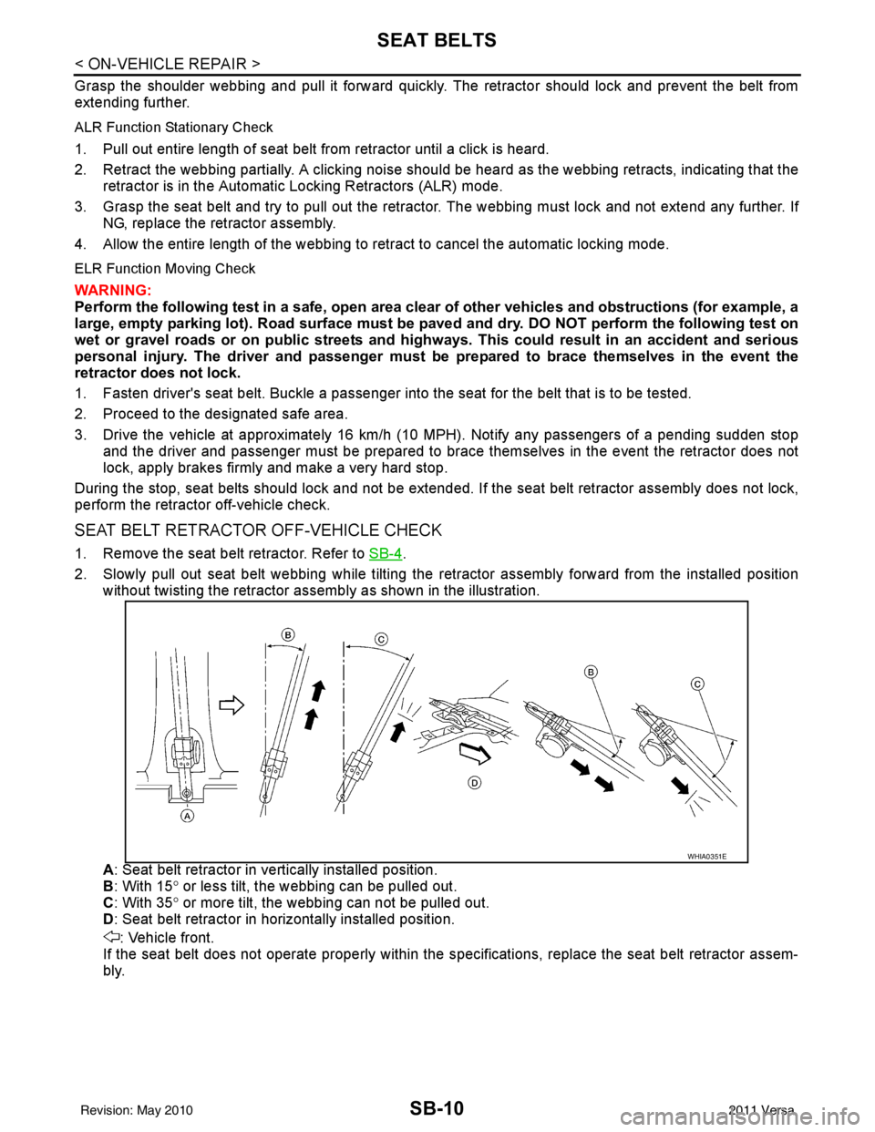
2. Slowly pull out seat belt webbing while tilting the re tractor assembly forward from the installed position
without twisting the retractor assemb ly as shown in the illustration.
A : Seat belt retractor in ve rtically installed position.
B : With 15 ° or less tilt, the webbing can be pulled out.
C : With 35 ° or more tilt, the webbing can not be pulled out.
D : Seat belt retractor in horizontally installed position.
: Vehicle front.
If the seat belt does not operate properly within the s pecifications, replace the seat belt retractor assem-
bly.
WHIA0351E
Revision: May 2010 2011 Versa
Page 3579 of 3787

SC-1
ELECTRICAL
C
DE
F
G H
I
J
L
M
SECTION SC
A
B
SC
N
O P
CONTENTS
STARTING & CHARGING SYSTEM
SERVICE INFORMATION .. ..........................2
PRECAUTIONS .............................................. .....2
Precaution for Supplemental Restraint System
(SRS) "AIR BAG" and "SEAT BELT PRE-TEN-
SIONER" ............................................................. ......
2
Precaution Necessary for Steering Wheel Rota-
tion After Battery Disconnect ............................... ......
2
PREPARATION ...................................................4
Special Service Tool ........................................... ......4
Commercial Service Tool ..........................................4
BATTERY ............................................................5
How to Handle Battery ........................................ ......5
Trouble Diagnosis with Multitasking Battery Diag-
nostic Station ....................................................... ......
7
Removal and Installation ...........................................7
Required Procedure After Battery Disconnection ......8
STARTING SYSTEM ..........................................9
System Description .............................................. .....9
Wiring Diagram - START - .......................................11
Trouble Diagnosis with Multitasking Battery Diag-
nostic Station ...........................................................
16
Removal and Installation HR16DE ..........................19
Removal and Installation MR18DE ..........................20
CHARGING SYSTEM .......................................21
System Description ..................................................21
Wiring Diagram - CHARGE - ...................................22
Trouble Diagnosis with Multitasking Battery Diag-
nostic Station ...........................................................
22
Removal and Installation .........................................25
SERVICE DATA AND SPECIFICATIONS
(SDS) .................................................................
27
Battery .....................................................................27
Starter ......................................................................27
Generator ................................................................27
Revision: May 2010 2011 Versa
Page 3580 of 3787
SC-2
< SERVICE INFORMATION >
PRECAUTIONS
SERVICE INFORMATION
PRECAUTIONS
Precaution for Supplemental Restraint System (SRS) "AIR BAG" and "SEAT BELT
PRE-TENSIONER"
INFOID:0000000005929006
The Supplemental Restraint System such as “A IR BAG” and “SEAT BELT PRE-TENSIONER”, used along
with a front seat belt, helps to reduce the risk or severity of injury to the driver and front passenger for certain
types of collision. This system includes seat belt switch inputs and dual stage front air bag modules. The SRS
system uses the seat belt switches to determine the front air bag deployment, and may only deploy one front
air bag, depending on the severity of a collision and w hether the front occupants are belted or unbelted.
Information necessary to service the system safely is included in the SRS and SB section of this Service Man-
ual.
WARNING:
• To avoid rendering the SRS inopera tive, which could increase the risk of personal injury or death in
the event of a collision which would result in air bag inflation, all maintenance must be performed by
an authorized NISSAN/INFINITI dealer.
• Improper maintenance, including in correct removal and installation of the SRS, can lead to personal
injury caused by unintent ional activation of the system. For re moval of Spiral Cable and Air Bag
Module, see the SRS section.
• Do not use electrical test equipmen t on any circuit related to the SRS unless instructed to in this
Service Manual. SRS wiring harn esses can be identified by yellow and/or orange harnesses or har-
ness connectors.
PRECAUTIONS WHEN USING POWER TOOLS (AIR OR ELECTRIC) AND HAMMERS
WARNING:
• When working near the Airbag Diagnosis Sensor Unit or other Airbag System sensors with the Igni-
tion ON or engine running, DO NOT use air or electri c power tools or strike near the sensor(s) with a
hammer. Heavy vibration could activate the sensor( s) and deploy the air bag(s), possibly causing
serious injury.
• When using air or electric power tools or hammers , always switch the Ignition OFF, disconnect the
battery, and wait at least 3 minu tes before performing any service.
Precaution Necessary for Steering W heel Rotation After Battery Disconnect
INFOID:0000000005929007
NOTE:
• This Procedure is applied only to models with Intelligent Key system and NATS (NISSAN ANTI-THEFT SYS-
TEM).
• Remove and install all control units after disconnecting both battery cables with the ignition knob in the
″LOCK ″ position.
• Always use CONSULT-III to perform self-diagnosis as a part of each function inspection after finishing work.
If DTC is detected, perform trouble diagnosis according to self-diagnostic results.
For models equipped with the Intelligent Key system and NATS, an electrically controlled steering lock mech-
anism is adopted on the key cylinder.
For this reason, if the battery is disconnected or if the battery is discharged, the steering wheel will lock and
steering wheel rotation will become impossible.
If steering wheel rotation is required when battery pow er is interrupted, follow the procedure below before
starting the repair operation.
OPERATION PROCEDURE
1. Connect both battery cables. NOTE:
Supply power using jumper cables if battery is discharged.
2. Use the Intelligent Key or mechanical key to turn the ignition switch to the ″ACC ″ position. At this time, the
steering lock will be released.
3. Disconnect both battery cables. The steering lock will remain released and the steering wheel can be rotated.
4. Perform the necessary repair operation.
Revision: May 2010 2011 Versa
Page 3604 of 3787
SC-26
< SERVICE INFORMATION >
CHARGING SYSTEM
REMOVAL
1. Disconnect the battery negative terminal. Refer to SC-7, "Removal and Installation".
2. Remove drive belt. Refer to EM-14, "
Removal and Installation" (HR16DE), EM-132, "Removal and Instal-
lation" (MR18DE).
3. Remove radiator reservoir tank. Refer to CO-16, "
Removal and Installation" (HR16DE), CO-40, "Removal
and Installation" (MR18DE).
4. Disconnect generator connector.
5. Remove “B” terminal nut.
6. Remove generator bolts.
7. Remove generator assembly from the vehicle.
GENERATOR PULLEY INSPECTION
• Check that the generator pulley does not rattle.
• Check that the generator pulley nut is properly tightened.
INSTALLATION
Installation is in the reverse order of removal.
CAUTION:
Be sure to tighten “B” terminal nut carefully.
1. Generator bracket bolt 2. Generator bracket3. Generator bolt
4. Generator 5. Generator "B" terminal harness 6. "B" terminal nut
7. Generator connector
Generator pulley nut : 118 N·m (12.0 kg-m, 87 ft-lb)
Revision: May 2010 2011 Versa
Page 3606 of 3787

SE-1
BODY
C
DE
F
G H
J
K L
M
SECTION SE
A
B
SE
N
O P
CONTENTS
SEAT
SERVICE INFORMATION .. ..........................2
PRECAUTIONS .............................................. .....2
Precaution for Supplemental Restraint System
(SRS) "AIR BAG" and "SEAT BELT PRE-TEN-
SIONER" ............................................................. ......
2
Precaution Necessary for Steering Wheel Rota-
tion After Battery Disconnect ............................... ......
2
Service Notice ...........................................................3
Precaution .................................................................3
PREPARATION ...................................................4
Special Service Tool ........................................... ......4
Commercial Service Tool ..........................................4
SQUEAK AND RATTLE TROUBLE DIAG-
NOSES ................................................................
5
Work Flow ........................................................... ......5
Generic Squeak and Rattle Troubleshooting ............7
Diagnostic Worksheet .......................................... .....9
FRONT SEAT ....................................................11
Driver Seat ...............................................................11
Passenger Seat .......................................................12
Removal and Installation .........................................12
Disassembly and Assembly .....................................13
REAR SEAT ......................................................15
Component Parts Drawing ......................................15
Removal and Installation .........................................16
Disassembly and Assembly .....................................18
Component Parts Drawing ......................................21
Removal and Installation .........................................22
Disassembly and Assembly .....................................24
Component Parts Drawing ......................................27
Removal and Installation .........................................28
Disassembly and Assembly .....................................28
Revision: May 2010 2011 Versa
Page 3607 of 3787
SE-2
< SERVICE INFORMATION >
PRECAUTIONS
SERVICE INFORMATION
PRECAUTIONS
Precaution for Supplemental Restraint System (SRS) "AIR BAG" and "SEAT BELT
PRE-TENSIONER"
INFOID:0000000006410247
The Supplemental Restraint System such as “A IR BAG” and “SEAT BELT PRE-TENSIONER”, used along
with a front seat belt, helps to reduce the risk or severity of injury to the driver and front passenger for certain
types of collision. This system includes seat belt switch inputs and dual stage front air bag modules. The SRS
system uses the seat belt switches to determine the front air bag deployment, and may only deploy one front
air bag, depending on the severity of a collision and w hether the front occupants are belted or unbelted.
Information necessary to service the system safely is included in the SRS and SB section of this Service Man-
ual.
WARNING:
• To avoid rendering the SRS inopera tive, which could increase the risk of personal injury or death in
the event of a collision which would result in air bag inflation, all maintenance must be performed by
an authorized NISSAN/INFINITI dealer.
• Improper maintenance, including incorrect removal and installation of the SRS can lead to personal
injury caused by unintent ional activation of the system. For re moval of Spiral Cable and Air Bag
Module, see the SRS section.
• Do not use electrical test equipmen t on any circuit related to the SRS unless instructed to in this
Service Manual. SRS wiring harn esses can be identified by yellow and/or orange harnesses or har-
ness connectors.
PRECAUTIONS WHEN USING POWER TOOLS (AIR OR ELECTRIC) AND HAMMERS
WARNING:
• When working near the Airbag Diagnosis Sensor Unit or other Airbag System sensors with the Igni-
tion ON or engine running, DO NOT use air or electri c power tools or strike near the sensor(s) with a
hammer. Heavy vibration could activate the sensor( s) and deploy the air bag(s), possibly causing
serious injury.
• When using air or electric power tools or hammers , always switch the Ignition OFF, disconnect the
battery, and wait at least 3 minu tes before performing any service.
Precaution Necessary for Steering W heel Rotation After Battery Disconnect
INFOID:0000000005929596
NOTE:
• This Procedure is applied only to models with Intelligent Key system and NATS (NISSAN ANTI-THEFT SYS-
TEM).
• Remove and install all control units after disconnecting both battery cables with the ignition knob in the
″LOCK ″ position.
• Always use CONSULT-III to perform self-diagnosis as a part of each function inspection after finishing work.
If DTC is detected, perform trouble diagnosis according to self-diagnostic results.
For models equipped with the Intelligent Key system and NATS, an electrically controlled steering lock mech-
anism is adopted on the key cylinder.
For this reason, if the battery is disconnected or if the battery is discharged, the steering wheel will lock and
steering wheel rotation will become impossible.
If steering wheel rotation is required when battery pow er is interrupted, follow the procedure below before
starting the repair operation.
OPERATION PROCEDURE
1. Connect both battery cables. NOTE:
Supply power using jumper cables if battery is discharged.
2. Use the Intelligent Key or mechanical key to turn the ignition switch to the ″ACC ″ position. At this time, the
steering lock will be released.
3. Disconnect both battery cables. The steering lock will remain released and the steering wheel can be rotated.
4. Perform the necessary repair operation.
Revision: May 2010 2011 Versa
Page 3616 of 3787
FRONT SEATSE-11
< SERVICE INFORMATION >
C
DE
F
G H
J
K L
M A
B
SE
N
O P
FRONT SEAT
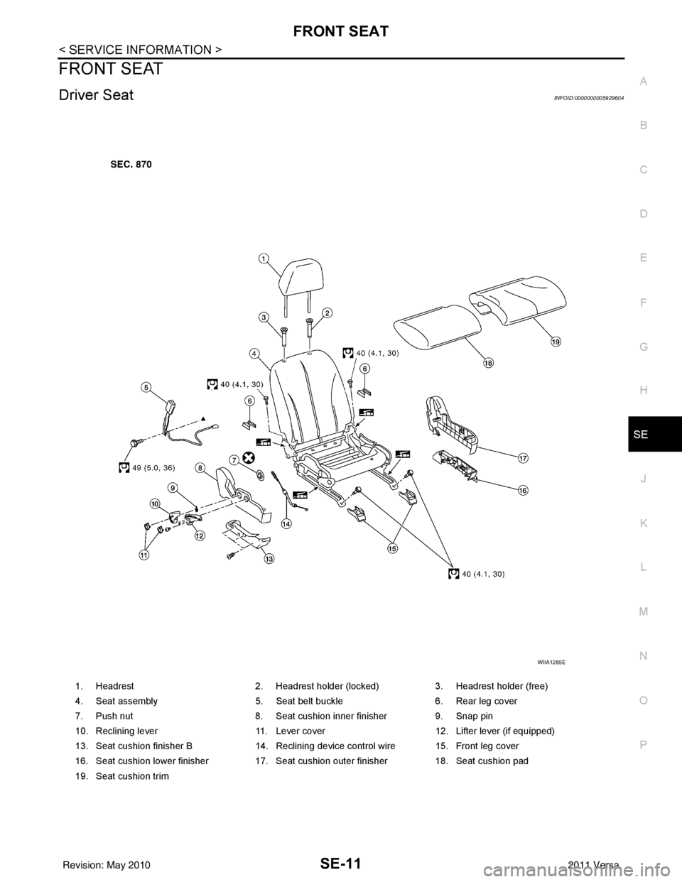
Driver SeatINFOID:0000000005929604
1. Headrest 2. Headrest holder (locked)3. Headrest holder (free)
4. Seat assembly 5. Seat belt buckle6. Rear leg cover
7. Push nut 8. Seat cushion inner finisher9. Snap pin
10. Reclining lever 11. Lever cover12. Lifter lever (if equipped)
13. Seat cushion finisher B 14. Reclining device control wire 15. Front leg cover
16. Seat cushion lower finisher 17. Seat cushion outer finisher 18. Seat cushion pad
19. Seat cushion trim
WIIA1285E
Revision: May 2010 2011 Versa
Page 3617 of 3787
SE-12
< SERVICE INFORMATION >
FRONT SEAT
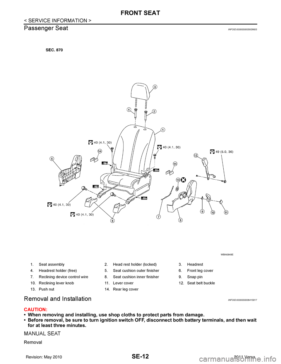
Passenger Seat
INFOID:0000000005929605
Removal and InstallationINFOID:0000000006415817
CAUTION:
• When removing and installing, use shop cloths to protect parts from damage.
• Before removal, be sure to turn ignition switch OFF, disconnect both battery terminals, and then wait
for at least three minutes.
MANUAL SEAT
Removal
1. Seat assembly 2. Head rest holder (locked) 3. Headrest
4. Headrest holder (free) 5. Seat cushion outer finisher6. Front leg cover
7. Reclining device control wire 8. Seat cushion inner finisher 9. Snap pin
10. Reclining lever knob 11. Lever cover 12. Seat belt buckle
13. Push nut 14. Rear leg cover
WBIA0848E
Revision: May 2010 2011 Versa