Page 3467 of 3787
HARNESSPG-47
< SERVICE INFORMATION >
C
DE
F
G H
I
J
L
M A
B
PG
N
O P
G4 B2 GR/2 : Rear bumper antenna C4 B14 Y/2 : Front LH seat belt pre-tensioner
B4 B3 B/4 : Yaw rate/ side/ decel G sensor C5 B15 Y/2 : LH side air bag (satellite) sensor
C4 B4 W/8 : To D201 G4 B16 BR/2 : License plate lamp LH
C4 B5 — : Body ground G4 B17 BR/2 : License plate lamp RH
E4 B6 W/1 : Rear door switch LH F3 B19 — : Body ground
C4 B7 — : Body ground F3 B21 W/2 : Luggage room lamp
C4 B8 W/3 : Front door switch LH A4 B23 W/16 : To M15
C4 B9 Y/12 : Air bag diagnosis sensor unit A4 B24 W/24 : To M16
C4 B10 Y/2 : Front LH side air bag module F3 B25 BR/6 : Rear combination lamp LH
B4 B13 W/4 : Seat belt buckle switch LH F3 B26 Y/2 : LH side curtain air bag module
Revision: May 2010 2011 Versa
Page 3468 of 3787
PG-48
< SERVICE INFORMATION >
HARNESS
BODY HARNESS (SEDAN)
ABMIA2321GB
G4 B2 GR/2 : Rear bumper antennaC4 B14 Y/2 : Front LH seat belt pre-tensioner
B4 B3 B/4 : Yaw rate/ side/ decel G sensor C5 B15 Y/2 : LH side air bag (satellite) sensor
C4 B4 W/8 : To D201 F2 B18 W/2 : High mounted stop lamp
C4 B5 — : Body ground E3 B19 — : Body ground
D3 B6 W/1 : Rear door switch LH F2 B21 W/2 : Luggage room lamp
Revision: May 2010 2011 Versa
Page 3469 of 3787
HARNESSPG-49
< SERVICE INFORMATION >
C
DE
F
G H
I
J
L
M A
B
PG
N
O P
BODY NO. 2 HARNESS (HATCHBACK)
C3 B7 — : Body ground A4 B23 W/16 : To M15
C4 B8 W/3 : Front door switch LH A4 B24 W/24 : To M16
B3 B9 Y/12 : Air bag diagnosis sensor unit G4 B25 BR/6 : Rear combination lamp LH
B3 B10 Y/2 : Front LH side air bag module E3 B26 Y/2 : LH side curtain air bag module
B4 B13 W/4 : Seat belt buckle switch LH F3 B32 BR/2 : Intelligent key warning buzzer (trunk)
ABMIA1595GB
Revision: May 2010 2011 Versa
Page 3470 of 3787

PG-50
< SERVICE INFORMATION >
HARNESS
D3 B100 GR/5 : Fuel level sensor unit and fuel pump C3 B116 W/1 : Rear door switch RH
G5 B101 W/16 : To M12E3 B117 — : Body ground
G5 B102 W/24 : To M13 B2 B118 Y/2 : RH side curtain air bag module
F3 B103 B/2 : Console power socket D3 B119 W/8 : To D301
A4 B104 GR/3 : EVAP control system pressure sensor G5 B120 W/24 : To M14
B3 B105 B/2 : EVAP canister vent control valve A3 B121 W/32 : Bluetooth control unit
G5 B106 W/4 : To M11 A3 B122 GR/1 : Bluetooth control unit
A2 B107 BR/6 : Rear combination lamp RH D2 B123 B/2 : Rear wheel sensor LH
E4 B108 W/3 : Front door switch RH C3 B124 B/2 : Rear wheel sensor RH
F4 B109 Y/2 : Front RH side air bag module F3 B125 GR/2 : Front console antenna
F4 B110 W/8 : To B300 C3 B126 GR/2 : Rear floor antenna
E5 B111 Y/2 : RH side air bag (satellite) sensor A2 B132 — : Body ground
F4 B112 W/4 : Seat belt buckle switch RH B2 B133 W/2 : To D400
F3 B113 Y/12 : Air bag diagnosis sensor unit B2 B134 W/12 : To D401
E4 B114 — : Body ground A2 B135 W/8 : Bluetooth control unit
E4 B115 Y/2 : Front RH seat belt pre-tensioner E5 B138 B/3 : Belt tension sensor
Revision: May 2010 2011 Versa
Page 3472 of 3787

PG-52
< SERVICE INFORMATION >
HARNESS
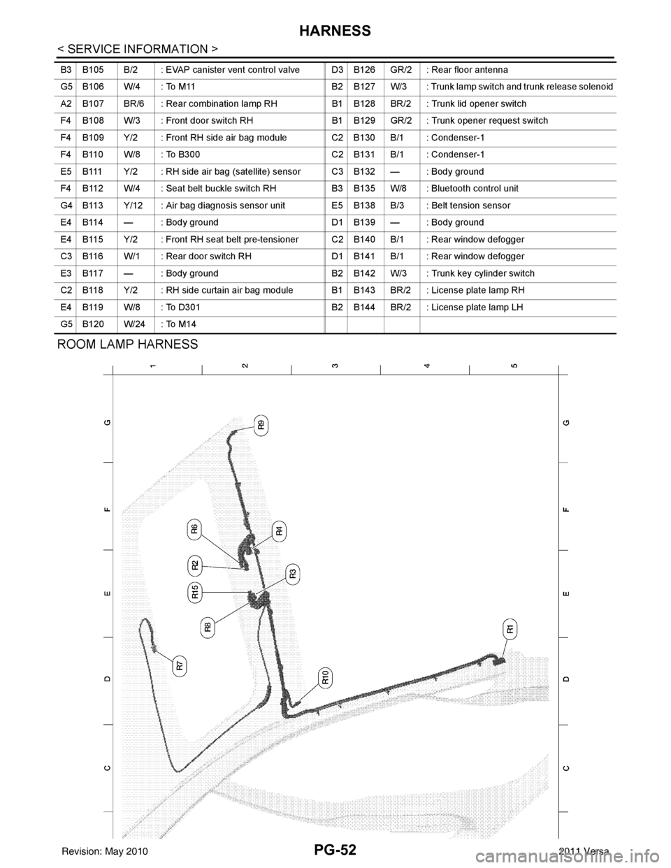
ROOM LAMP HARNESS
B3 B105 B/2 : EVAP canister vent control valve D3 B126 GR/2 : Rear floor antenna
G5 B106 W/4 : To M11B2 B127 W/3 : Trunk lamp switch and trunk release solenoid
A2 B107 BR/6 : Rear combination lamp RH B1 B128 BR/2 : Trunk lid opener switch
F4 B108 W/3 : Front door switch RH B1 B129 GR/2 : Trunk opener request switch
F4 B109 Y/2 : Front RH side air bag module C2 B130 B/1 : Condenser-1
F4 B110 W/8 : To B300 C2 B131 B/1 : Condenser-1
E5 B111 Y/2 : RH side air bag (satellite) sensor C3 B132 — : Body ground
F4 B112 W/4 : Seat belt buckle switch RH B3 B135 W/8 : Bluetooth control unit
G4 B113 Y/12 : Air bag diagnosis sensor unit E5 B138 B/3 : Belt tension sensor
E4 B114 — : Body ground D1 B139 — : Body ground
E4 B115 Y/2 : Front RH seat belt pre-tensioner C2 B140 B/1 : Rear window defogger
C3 B116 W/1 : Rear door switch RH D1 B141 B/1 : Rear window defogger
E3 B117 — : Body ground B2 B142 W/3 : Trunk key cylinder switch
C2 B118 Y/2 : RH side curtain air bag module B1 B143 BR/2 : License plate lamp RH
E4 B119 W/8 : To D301 B2 B144 BR/2 : License plate lamp LH
G5 B120 W/24 : To M14
Revision: May 2010 2011 Versa
Page 3487 of 3787

HARNESS CONNECTORPG-67
< SERVICE INFORMATION >
C
DE
F
G H
I
J
L
M A
B
PG
N
O P
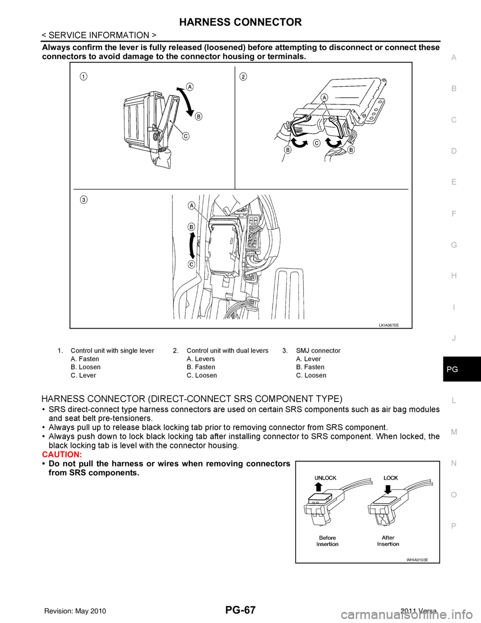
Always confirm the lever is fully released (loosened) before attempting to disconnect or connect these
connectors to avoid damage to th e connector housing or terminals.
HARNESS CONNECTOR (DIRECT-CONNECT SRS COMPONENT TYPE)
• SRS direct-connect type harness connectors are used on certain SRS components such as air bag modules
and seat belt pre-tensioners.
• Always pull up to release black locking tab prior to removing connector from SRS component.
• Always push down to lock black locking tab after installing connector to SRS component. When locked, the
black locking tab is level with the connector housing.
CAUTION:
• Do not pull the harness or wir es when removing connectors
from SRS components.
LKIA0670E
1. Control unit with single lever
A. Fasten
B. Loosen
C. Lever 2. Control unit with dual levers
A. Levers
B. Fasten
C. Loosen 3. SMJ connector
A. Lever
B. Fasten
C. Loosen
WHIA0103E
Revision: May 2010 2011 Versa
Page 3495 of 3787

PS-1
STEERING
C
DE
F
H I
J
K L
M
SECTION PS
A
B
PS
N
O P
CONTENTS
POWER STEERING SYSTEM
SERVICE INFORMATION .. ..........................2
PRECAUTIONS .............................................. .....2
Precaution for Supplemental Restraint System
(SRS) "AIR BAG" and "SEAT BELT PRE-TEN-
SIONER" ............................................................. ......
2
Precaution Necessary for Steering Wheel Rota-
tion After Battery Disconnect ............................... ......
2
Precaution for Steering System .......................... ......3
PREPARATION .............................................. .....4
Special Service Tool ........................................... ......4
Commercial Service Tool ..........................................4
NOISE, VIBRATION AND HARSHNESS
(NVH) TROUBLESHOOTING .............................
5
NVH Troubleshooting Chart ................................ ......5
STEERING WHEEL .............................................6
On-Vehicle Inspection and Service ..................... ......6
Removal and Installation ..................................... .....7
STEERING COLUMN ........................................10
Removal and Installation .........................................10
STEERING SHAFT ...........................................13
Removal and Installation .........................................13
POWER STEERING GEAR ..............................15
Removal and Installation .........................................15
Disassembly and Assembly .....................................15
SERVICE DATA AND SPECIFICATIONS
(SDS) .................................................................
20
Steering Wheel ........................................................20
Steering Angle .........................................................20
Steering Column ......................................................20
Steering Outer Socket and Inner Socket .................20
Steering Gear ...................................................... ....21
Revision: May 2010 2011 Versa
Page 3496 of 3787

PS-2
< SERVICE INFORMATION >
PRECAUTIONS
SERVICE INFORMATION
PRECAUTIONS
Precaution for Supplemental Restraint System (SRS) "AIR BAG" and "SEAT BELT
PRE-TENSIONER"
INFOID:0000000006409484
The Supplemental Restraint System such as “A IR BAG” and “SEAT BELT PRE-TENSIONER”, used along
with a front seat belt, helps to reduce the risk or severity of injury to the driver and front passenger for certain
types of collision. This system includes seat belt switch inputs and dual stage front air bag modules. The SRS
system uses the seat belt switches to determine the front air bag deployment, and may only deploy one front
air bag, depending on the severity of a collision and w hether the front occupants are belted or unbelted.
Information necessary to service the system safely is included in the SRS and SB section of this Service Man-
ual.
WARNING:
• To avoid rendering the SRS inopera tive, which could increase the risk of personal injury or death in
the event of a collision which would result in air bag inflation, all maintenance must be performed by
an authorized NISSAN/INFINITI dealer.
• Improper maintenance, including incorrect removal and installation of the SRS can lead to personal
injury caused by unintent ional activation of the system. For re moval of Spiral Cable and Air Bag
Module, see the SRS section.
• Do not use electrical test equipmen t on any circuit related to the SRS unless instructed to in this
Service Manual. SRS wiring harn esses can be identified by yellow and/or orange harnesses or har-
ness connectors.
PRECAUTIONS WHEN USING POWER TOOLS (AIR OR ELECTRIC) AND HAMMERS
WARNING:
• When working near the Airbag Diagnosis Sensor Unit or other Airbag System sensors with the Igni-
tion ON or engine running, DO NOT use air or electri c power tools or strike near the sensor(s) with a
hammer. Heavy vibration could activate the sensor( s) and deploy the air bag(s), possibly causing
serious injury.
• When using air or electric power tools or hammers , always switch the Ignition OFF, disconnect the
battery, and wait at least 3 minu tes before performing any service.
Precaution Necessary for Steering W heel Rotation After Battery Disconnect
INFOID:0000000005929628
NOTE:
• This procedure is applied only to models with Intel ligent Key system and NATS (NISSAN ANTI-THEFT SYS-
TEM).
• Remove and install all control units after disconnecting both battery cables with the ignition switch in the
″ LOCK ″ position.
• Always use CONSULT-III to perform self-diagnosis as a part of each function inspection after finishing work.
If DTC is detected, perform trouble diagnosis according to self-diagnostic results.
For models equipped with the Intelligent Key system and NATS, an electrically controlled steering lock mech-
anism is adopted on the key cylinder.
For this reason, if the battery is disconnected or if the battery is discharged, the steering wheel will lock and
steering wheel rotation will become impossible.
If steering wheel rotation is required when battery pow er is interrupted, follow the procedure below before
starting the repair operation.
OPERATION PROCEDURE
1. Connect both battery cables. NOTE:
Supply power using jumper cables if battery is discharged.
2. Use the Intelligent Key or mechanical key to turn the ignition switch to the ″ACC ″ position. At this time, the
steering lock will be released.
3. Disconnect both battery cables. The steering lock will remain released and the steering wheel can be rotated.
4. Perform the necessary repair operation.
Revision: May 2010 2011 Versa