2011 NISSAN LATIO clutch
[x] Cancel search: clutchPage 393 of 3787

AT-376
< SERVICE INFORMATION >
SERVICE DATA AND SPECIFICATIONS (SDS)
Unit: mm (in)
AccumulatorINFOID:0000000005928316
RETURN SPRINGS
Unit: mm (in)
Unit: mm (in)
O-RINGS
Unit: mm (in)
Clutches and BrakesINFOID:0000000005928317
REVERSE CLUTCH
Locationspring designation Free length (l) Outer diameter (D)
Upper body L14 Pilot valve spring
38.98 (1.5346)8.9 (0.350)
L15 1–2 accumulator valve spring
20.5 (0.807)6.95 (0.2736)
1–2 accumulator piston spring 55.66 (2.1913)19.5 (0.768)
L16 1st reducing valve spring 27.0 (1.063)7.0 (0.276)
L17 3–2 timing valve spring 23.0 (0.906)6.65 (0.2618)
L18 Overrun clutch reducing valve spring37.5 (1.476)7.0 (0.276)
L19 Torque converter relief valve spring 33.3 (1.311)9.0 (0.354)
L20 Torque converter clutch control valve spring 53.01 (2.0870)6.5 (0.256)
L21 Cooler check valve spring 28.04 (1.1039)7.15 (0.2815)
Lower body L3 Pressure regulator valve spring
45.0 (1.772)15.0 (0.591)
L4 Overrun clutch control valve spring 21.7 (0.854)7.0 (0.276)
L5 Accumulator control valve spring 22.0 (0.866)6.5 (0.256)
L6 Shift valve A spring 21.7 (0.854)7.0 (0.276)
L7 Shuttle valve spring 51.0 (2.008)5.65 (0.2224)
L12 Shift valve B spring 21.7 (0.854)7.0 (0.276)
L13 Pressure modifier valve spring
32.0 (1.260)6.9 (0.272)
Pressure modifier piston spring 30.5 (1.201)9.8 (0.386)
— Line pressure relief valve spring 17.02 (0.6701)8.0 (0.315)
— Torque converter pressure holding spring 9.0 (0.354)7.3 (0.287)
Location Free length (L1)
Servo release accumulator 62.8 (2.472)
LocationLength (L2)
N-D accumulator 46.5 (1.831)
LocationInner diameter (Small) Inner diameter (Large)
Servo release accumulator 26.9 (1.059)44.2 (1.740)
N-D accumulator 34.6 (1.362)39.4 (1.551)
Number of drive plates 2
Number of driven plates 2
Drive plate thickness [mm (in)] Standard
2.0 (0.079)
Allowable limit 1.8 (0.071)
Driven plate thickness [mm (in)] Standard 2.0 (0.079)
Clearance [mm (in)] Standard
0.5 - 0.8 (0.020 - 0.031)
Allowable limit 1.2 (0.047)
Revision: May 2010 2011 Versa
Page 394 of 3787

SERVICE DATA AND SPECIFICATIONS (SDS)AT-377
< SERVICE INFORMATION >
DE
F
G H
I
J
K L
M A
B
AT
N
O P
HIGH CLUTCH
FORWARD CLUTCH
OVERRUN CLUTCH
LOW & REVERSE BRAKE
BRAKE BAND
Applied model HR16DE engineMR18DE engine
Number of drive plates 34
Number of driven plates 57 (1
*1 + 6*2)
Drive plate thickness [mm (in)] Standard
1.6 (0.063) 1.6 (0.063)
Allowable limit 1.4 (0.055) 1.4 (0.055)
Driven plate thickness [mm (in)] Standard 2.0 (0.079)
*1*2
2.0 (0.079) 1.5 (0.059)
Clearance [mm (in)] Standard
1.4 - 1.8 (0.055 - 0.071) 1.4 - 1.8 (0.055 - 0.071)
Allowable limit 2.4 (0.094) 2.6 (0.102)
Number of drive plates 5
Number of driven plates 5
Drive plate thickness [mm (in)] Standard
1.8 (0.071)
Allowable limit 1.6 (0.063)
Driven plate thickness [mm (in)] Standard 2.0 (0.079)
Clearance [mm (in)] Standard
0.45 - 0.85 (0.0177 - 0.0335)
Allowable limit 1.85 (0.0728)
Number of drive plates 3
Number of driven plates 4
Drive plate thickness [mm (in)] Standard
1.6 (0.063)
Allowable limit 1.4 (0.055)
Driven plate thickness [mm (in)] Standard 2.0 (0.079)
Clearance [mm (in)] Standard
1.0 - 1.4 (0.039 - 0.055)
Allowable limit 2.0 (0.079)
Applied model HR16DE engineMR18DE engine
Number of drive plates 45
Number of driven plates 45
Drive plate thickness [mm
(in)] Standard
2.0 (0.079)2.0 (0.079)
Allowable limit 1.8 (0.071)1.8 (0.071)
Driven plate thickness [mm
(in)] Standard
2.0 (0.079)2.0 (0.079)
Clearance [mm (in)] Standard
1.4 - 1.8 (0.055 - 0.071) 1.4 - 1.8 (0.055 - 0.071)
Allowable limit 2.6 (0.102)2.8 (0.110)
Anchor end pin tightening torque [N·m (kg-m, in-lb)] 4.9 (0.50, 43)
Number of returning revolutions for anchor end pin 2.5
Lock nut tightening torque [N·m (kg-m, ft-lb)] 33.9 (3.5, 25)
Revision: May 2010 2011 Versa
Page 396 of 3787

SERVICE DATA AND SPECIFICATIONS (SDS)AT-379
< SERVICE INFORMATION >
DE
F
G H
I
J
K L
M A
B
AT
N
O P
Unit: mm (in)
Output ShaftINFOID:0000000005928324
SEAL RING CLEARANCE
SEAL RING
Unit: mm (in)
TURNING TORQUE (FOR HR16DE ENGINE MODELS)
END PLAY (FOR MR18DE ENGINE MODELS)
Bearing RetainerINFOID:0000000005928325
SEAL RING CLEARANCE
Total End PlayINFOID:0000000005928326
Reverse Clutch End PlayINFOID:0000000005928327
Removal and InstallationINFOID:0000000005928328
Shift Solenoid ValvesINFOID:0000000005928329
Return spring Free length
2nd servo return sp ring 32.5 (1.280)
OD servo return sp ring 38.52 (1.5165)
Output shaft seal ring clearance [mm (in)]Standard 0.10 - 0.25 (0.0039 - 0.0098)
Allowable limit
0.25 (0.0098)
Outer diameter Inner diameter Width
29.5 (1.161) 26.2 (1.031)1.95 (0.0768)
Turning torque of output shaft ·m (kg-m, in-lb) 0.25 - 0.88 (0.03 - 0.08, 3 - 7)
Output shaft end play mm (in) 0 - 0.5 (0 - 0.020)
Bearing retainer seal ring clearance [mm (in)]Standard 0.10 - 0.27 (0.0039 - 0.0106)
Allowable limit
0.27 (0.0106)
Total end play [mm (in)] 0.25 - 0.55 (0.0098 - 0.0217)
Reverse clutch end play [mm (in)] 0.65 - 1.0 (0.0256 - 0.039)
Engine HR16DE MR18DE
Distance between end of converter housing and torque converter [mm (in)] 16.2 (0.638)14.4 (0.567)
Gear position 1234
Shift solenoid valve A ON (Closed)OFF (Open)OFF (Open)ON (Closed)
Shift solenoid valve B ON (Closed)ON (Closed) OFF (Open)OFF (Open)
Revision: May 2010 2011 Versa
Page 397 of 3787

AT-380
< SERVICE INFORMATION >
SERVICE DATA AND SPECIFICATIONS (SDS)
Solenoid Valves
INFOID:0000000005928330
A/T Fluid Temperature SensorINFOID:0000000005928331
Remarks: Specification data are reference values.
Output Speed SensorINFOID:0000000005928332
Dropping ResistorINFOID:0000000005928333
Input Speed SensorINFOID:0000000005928334
Solenoid valve designation Resistance (Approx.)Terminal
Shift solenoid valve A 20 - 30 Ω 2
Shift solenoid valve B 5 - 20 Ω1
Overrun clutch solenoid valve 20 - 30 Ω 3
Line pressure solenoid valve 2.5 - 5.0 Ω 4
Torque converter clutch solenoid valve 5 - 20 Ω 5
Condition Specification (Approx.)
Cold [20 °C (68 °F)]
↓
Hot [80 °C (176 °F)] 1.5V
↓
0.5V 2.5 k
Ω
↓
0.3 k Ω
Condition Judgment standard
When driving at 20 km/h (12 MPH) 150 Hz (Approx.)
Resistance 12Ω (Approx.)
Condition Judgment standard
When driving at 20 km/h (12 MPH) 360 Hz (Approx.)
Revision: May 2010 2011 Versa
Page 518 of 3787

BL-8
< SERVICE INFORMATION >
SQUEAK AND RATTLE TROUBLE DIAGNOSES
If the noise can be duplicated easily during the test drive, to help identify the source of the noise, try to dupli-
cate the noise with the vehicle stopped by doing one or all of the following:
1) Close a door.
2) Tap or push/pull around the area where the noise appears to be coming from.
3) Rev the engine.
4) Use a floor jack to recreate vehicle “twist”.
5) At idle, apply engine load (electrical load, half-clutch on M/T model, drive position on A/T model).
6) Raise the vehicle on a hoist and hit a tire with a rubber hammer.
• Drive the vehicle and attempt to duplicate the conditions the customer states exist when the noise occurs.
• If it is difficult to duplicate the noise, drive the v ehicle slowly on an undulating or rough road to stress the
vehicle body.
CHECK RELATED SERVICE BULLETINS
After verifying the customer concern or symptom, chec k ASIST for Technical Service Bulletins (TSBs) related
to that concern or symptom.
If a TSB relates to the symptom, follo w the procedure to repair the noise.
LOCATE THE NOISE AND IDENTIFY THE ROOT CAUSE
1. Narrow down the noise to a general area.To help pinpoint the source of the noise, use a listening tool
(Chassis Ear: J-39570, Engine Ear: J-39565 and mechanic's stethoscope).
2. Narrow down the noise to a more specific area and identify the cause of the noise by:
• removing the components in the area that you suspect the noise is coming from.
Do not use too much force when removing clips and fasteners, otherwise clips and fasteners can be broken
or lost during the repair, resulting in the creation of new noise.
• tapping or pushing/pulling the component that you suspect is causing the noise.
Do not tap or push/pull the component with excessive force, otherwise the noise will be eliminated only tem-
porarily.
• feeling for a vibration with your hand by touching the component(s) that you suspect is (are) causing the
noise.
• placing a piece of paper between components that you suspect are causing the noise.
• looking for loose components and contact marks. Refer to BL-9, "
Generic Squeak and Rattle Troubleshooting".
REPAIR THE CAUSE
• If the cause is a loose component, tighten the component securely.
• If the cause is insufficient clearance between components:
- separate components by repositioning or loos ening and retightening the component, if possible.
- insulate components with a suitable insulator such as urethane pads, foam blocks, felt cloth tape or urethane tape. A NISSAN Squeak and Rattle Kit (J-43980) is av ailable through your authorized NISSAN Parts Depart-
ment.
CAUTION:
Do not use excessive force as many components are constructed of plastic and may be damaged.
Always check with the Parts Department for the latest parts information.
The following materials are contained in the NISSAN Squeak and Rattle Kit (J-43980). Each item can be
ordered separately as needed.
URETHANE PADS [1.5 mm (0.059 in) thick]
Insulates connectors, harness, etc.
76268-9E005: 100 ×135 mm (3.94× 5.31 in)/76884-71L01: 60 ×85 mm (2.36 ×3.35 in)/76884-71L02: 15 ×25
mm (0.59× 0.98 in)
INSULATOR (Foam blocks)
Insulates components from contact. Can be used to fill space behind a panel.
73982-9E000: 45 mm (1.77 in) thick, 50 ×50 mm (1.97 ×1.97 in)/73982-50Y00: 10 mm (0.39 in) thick,
50× 50 mm (1.97 ×1.97 in)
INSULATOR (Light foam block)
80845-71L00: 30 mm (1.18 in) thick, 30 ×50 mm (1.18 ×1.97 in)
FELT CLOTH TAPE
Used to insulate where movemen t does not occur. Ideal for instrument panel applications.
68370-4B000: 15 ×25 mm (0.59× 0.98 in) pad/68239-13E00: 5 mm (0.20 in ) wide tape roll. The following
materials not found in the kit can also be used to repair squeaks and rattles.
UHMW (TEFLON) TAPE
Insulates where slight movement is present. Ideal for inst rument panel applications.
Revision: May 2010 2011 Versa
Page 851 of 3787

BR-4
< SERVICE INFORMATION >
PREPARATION
PREPARATION
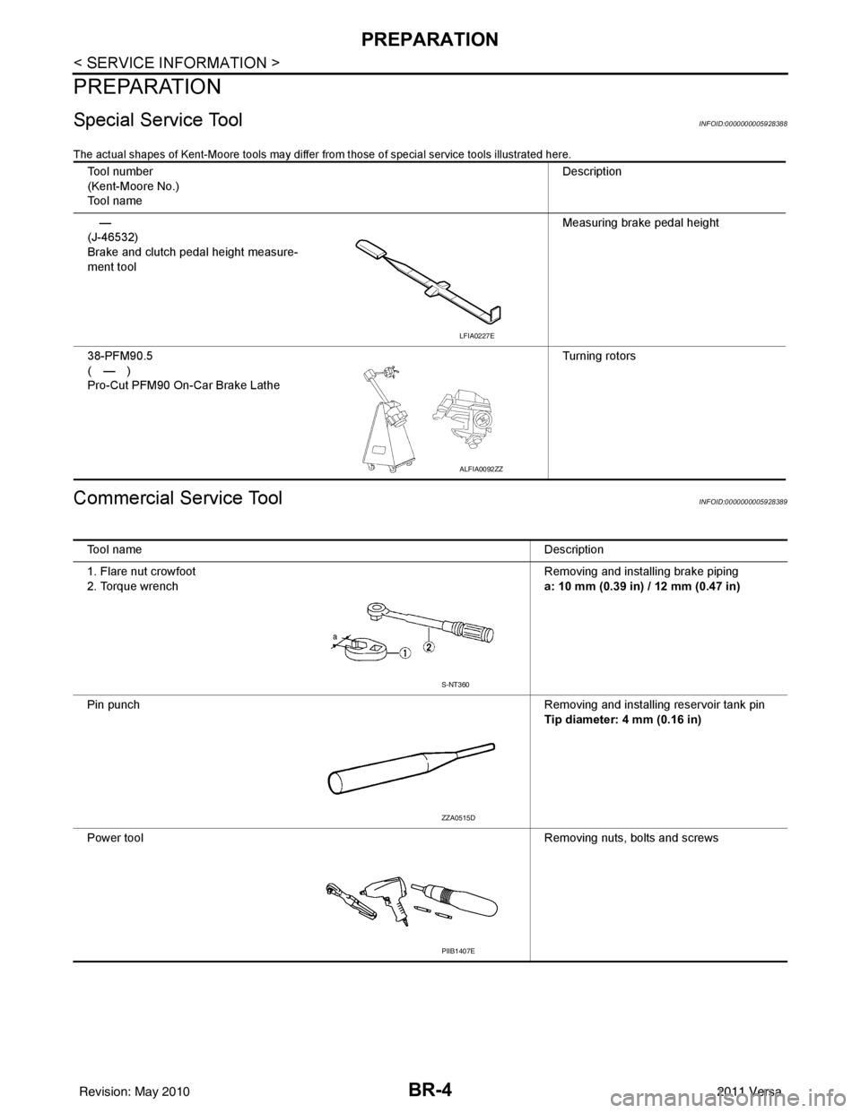
Special Service ToolINFOID:0000000005928388
The actual shapes of Kent-Moore tools may differ from those of special service tools illustrated here.
Commercial Service ToolINFOID:0000000005928389
Tool number
(Kent-Moore No.)
Tool name Description
—
(J-46532)
Brake and clutch pedal height measure-
ment tool Measuring brake pedal height
38-PFM90.5
(—)
Pro-Cut PFM90 On-Car Brake Lathe Turning rotors
LFIA0227E
ALFIA0092ZZ
Tool name
Description
1. Flare nut crowfoot
2. Torque wrench Removing and installing brake piping
a: 10 mm (0.39 in) / 12 mm (0.47 in)
Pin punch Removing and installing reservoir tank pin
Tip diameter: 4 mm (0.16 in)
Power tool Removing nuts, bolts and screws
S-NT360
ZZA0515D
PIIB1407E
Revision: May 2010 2011 Versa
Page 862 of 3787

BRAKE MASTER CYLINDERBR-15
< SERVICE INFORMATION >
C
DE
G H
I
J
K L
M A
B
BR
N
O P
BRAKE MASTER CYLINDER
On-Board InspectionINFOID:0000000005928402
LEAK INSPECTION
• Check for leaks around the master cylinder installation surface, the reservoir tank installation surface, and all the brake tube connections.
Removal and InstallationINFOID:0000000005928403
CAUTION:
Be careful not to splash brake fluid on painted areas; it may cause paint damage. If brake fluid is
splashed on painted areas, immediately wipe th em with cloth and wash it away with water.
REMOVAL
1. Drain the brake fluid. Refer to BR-9, "Drain and Refill".
2. Remove the battery. Refer to SC-7, "
Removal and Installation".
3. Remove the air duct. Refer to EM-135, "
Removal and Installation".
4. Remove the air cleaner. Refer to EM-135, "
Removal and Installation".
5. Disconnect the brake fluid level switch harness connector.
6. Disconnect the clutch hose from the reservoir tank, if equipped.
7. Remove the brake tube from master cylinder using a suitable tool.
8. Remove the master cylinder assembly nuts, and remove master cylinder assembly.
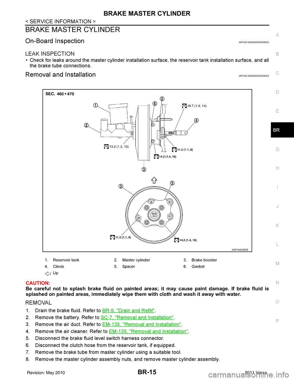
1. Reservoir tank 2. Master cylinder 3. Brake booster
4. Clevis 5. Spacer 6. Gasket
Up
AWFIA0530GB
Revision: May 2010 2011 Versa
Page 863 of 3787

BR-16
< SERVICE INFORMATION >
BRAKE MASTER CYLINDER
INSTALLATION
CAUTION:
• Refill using recommended brake fluid. Refer to MA-14, "
Fluids and Lubricants".
• Never reuse drained brake fluid.
• Check if the rod of primary piston has dust or scratches.
1. Install master cylinder to brake booster assembly, and tighten nuts to the specified torque.
CAUTION:
• Do not damage or strain rod of primary piston.
• Apply silicone grease for O-ring, primary piston rod andto inside of booster.
2. Install brake tube to master cylinder, and temporarily tighten the flare nuts on the brake tube to master cyl- inder by hand.
3. Install brake tube to brake hose, then tighten flare nut to the specified torque using a flare nut torque
wrench. Refer to BR-11, "
Hydraulic Circuit".
4. Connect the clutch hose to the reservoir tank, if equipped.
5. Connect brake fluid level switch harness connector.
6. Install the air cleaner. Refer to EM-135, "
Removal and Installation".
7. Install the air duct. Refer to EM-135, "
Removal and Installation".
8. Install the battery. Refer to SC-7, "
Removal and Installation".
9. Refill with new brake fluid and bleed the air from the brake hydraulic system. Refer toBR-9, "
Bleeding
Brake System".
Disassembly and AssemblyINFOID:0000000005928404
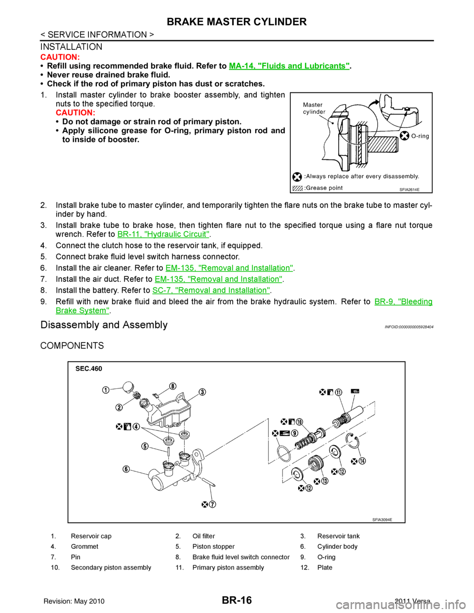
COMPONENTS
SFIA2614E
1. Reservoir cap2. Oil filter 3. Reservoir tank
4. Grommet 5. Piston stopper 6. Cylinder body
7. Pin 8. Brake fluid level switch connector 9. O-ring
10. Secondary piston assembly 11. Primary piston assembly 12. Plate
SFIA3094E
Revision: May 2010 2011 Versa