2011 NISSAN LATIO clutch
[x] Cancel search: clutchPage 208 of 3787
TROUBLE DIAGNOSIS FOR SYMPTOMSAT-191
< SERVICE INFORMATION >
DE
F
G H
I
J
K L
M A
B
AT
N
O P
A/T does not shift from D2 to D3 at the specified speed on “Cruise Test — Part 1” and “Cruise Test —
Part 2”.
DIAGNOSTIC PROCEDURE
1.CHECK SYMPTOM
Check symptom. Refer to AT-56, "
Check at Idle" and AT-58, "Cruise Test - Part 1" .
Are
“Vehicle Does Not Creep Forward in “D”, “2” or “1” Position” and “Vehicle Cannot Be Started from D1” OK?
YES >> GO TO 2.
NO >> Go to AT-186, "
Vehicle Does Not Creep Forward in "D", "2" or "1" Position" and AT-187, "Vehicle
Cannot Be Started from D1" .
2.CHECK A/T POSITION
Check A/T position. Refer to AT-217, "
Checking of A/T Position" .
OK or NG
OK >> GO TO 3.
NG >> Adjust A/T position. Refer to AT-217, "
Adjustment of A/T Position" .
3.CHECK OUTPUT SPEED SENSOR AND VEHICLE SPEED SIGNAL CIRCUIT
Check output speed sensor and vehicle speed signal circuit. Refer to AT-100
and AT-153 .
OK or NG
OK >> GO TO 4.
NG >> Repair or replace output speed sensor and vehicle speed signal circuits.
4.CHECK ACCELERATOR PEDAL POSITION SENSOR
Check accelerator pedal position sensor. Refer to EC-415, "
Description" (HR16DE), EC-982, "Component
Description" (MR18DE).
OK or NG
OK >> GO TO 5.
NG >> Repair or replace accelerator pedal position sensor.
5.CHECK A/T FLUID CONDITION
1. Remove oil pan. Refer to AT-237, "
Component" .
2. Check A/T fluid condition. Refer to AT-51, "
Inspections Before Trouble Diagnosis" .
OK or NG
OK >> GO TO 7.
NG >> GO TO 6.
6.DETECT MALFUNCTIONING ITEM
1. Remove control valve assembly. Refer to AT-222, "
Control Valve Assembly and Accumulators" .
2. Check the following items:
- Shift valve B
- Shift solenoid valve B
- Pilot valve
- Pilot filter
3. Disassemble A/T. Refer to AT-257, "
Disassembly" .
4. Check the following items:
- Servo piston assembly
- High clutch assembly. Refer to AT-302, "
High Clutch" .
- Oil pump assembly. Refer to AT-278, "
Oil Pump" .
OK or NG
OK >> GO TO 8.
NG >> Repair or replace damaged parts.
7.DETECT MALFUNCTIONING ITEM
1. Remove control valve assembly. Refer to AT-222, "
Control Valve Assembly and Accumulators" .
2. Check the following items:
- Shift valve B
Revision: May 2010 2011 Versa
Page 210 of 3787
TROUBLE DIAGNOSIS FOR SYMPTOMSAT-193
< SERVICE INFORMATION >
DE
F
G H
I
J
K L
M A
B
AT
N
O P
5.DETECT MALFUNCTIONING ITEM
1. Remove control valve assembly. Refer to AT-222, "
Control Valve Assembly and Accumulators" .
2. Check the following items:
- Shift valve A
- Overrun clutch control valve
- Shift solenoid valve A
- Overrun clutch solenoid valve
- Pilot valve
- Pilot filter
3. Disassemble A/T. Refer to AT-257, "
Disassembly" .
4. Check the following items:
- Servo piston assembly
- Brake band
- Torque converter. Refer to AT-257, "
Disassembly" .
- Oil pump assembly. Refer to AT-278, "
Oil Pump" .
OK or NG
OK >> GO TO 7.
NG >> Repair or replace damaged parts.
6.DETECT MALFUNCTIONING ITEM
1. Remove control valve assembly. Refer to AT-222, "
Control Valve Assembly and Accumulators" .
2. Check the following items:
- Shift valve A
- Overrun clutch control valve
- Shift solenoid valve A
- Pilot valve
- Pilot filter
OK or NG
OK >> GO TO 7.
NG >> Repair or replace damaged parts.
7.CHECK SYMPTOM
Check again. Refer to AT-58, "
Cruise Test - Part 1" and AT-61, "Cruise Test - Part 2" .
OK or NG
OK >> INSPECTION END
NG >> GO TO 8.
8.CHECK TCM
1. Check TCM input/output signals. Refer to AT-75, "
TCM Terminal and Reference Value" .
2. If NG, recheck TCM pin terminals for dam age or loose connection with harness connector.
OK or NG
OK >> INSPECTION END
NG >> Repair or replace damaged parts.
A/T Does Not Perform Lock-upINFOID:0000000005928258
SYMPTOM:
A/T does not perform lock-up at the specifi ed speed on “Cruise Test — Part 1”.
DIAGNOSTIC PROCEDURE
1.CHECK SELF-DIAGNOSTIC RESULTS
Perform self-diagnosis. Refer to AT-77, "
CONSULT-III Function (TRANSMISSION)" or AT-82, "Diagnosis Pro-
cedure without CONSULT-III" .
Is any malfunction detected by self-diagnostic results?
YES >> Check the malfuncti oning system. Refer to AT-77, "CONSULT-III Function (TRANSMISSION)" or
AT-82, "
Diagnosis Procedure without CONSULT-III" .
NO >> GO TO 2.
Revision: May 2010 2011 Versa
Page 211 of 3787

AT-194
< SERVICE INFORMATION >
TROUBLE DIAGNOSIS FOR SYMPTOMS
2.CHECK ACCELERATOR PEDAL POSITION SENSOR
Check accelerator pedal position sensor. Refer to EC-415, "
Description" (HR16DE), EC-982, "Component
Description" (MR18DE).
OK or NG
OK >> GO TO 3.
NG >> Repair or replace accelerator pedal position sensor.
3.DETECT MALFUNCTIONING ITEM
1. Remove control valve. Refer to AT-222, "
Control Valve Assembly and Accumulators" .
2. Check following items:
- Torque converter clutch control valve
- Torque converter clutch solenoid valve
- Torque converter relief valve
- Pilot valve
- Pilot filter
3. Disassemble A/T. Refer to AT-257, "
Disassembly" .
4. Check the following items:
- Torque converter. Refer to AT-257, "
Disassembly" .
OK or NG
OK >> GO TO 4.
NG >> Repair or replace damaged parts.
4.CHECK SYMPTOM
Check again. Refer to AT-58, "
Cruise Test - Part 1" .
OK or NG
OK >> INSPECTION END
NG >> GO TO 5.
5.CHECK TCM
1. Check TCM input/output signals. Refer to AT-75, "
TCM Terminal and Reference Value" .
2. If NG, recheck TCM pin terminals for damage or loose connection with harness connector.
OK or NG
OK >> INSPECTION END
NG >> Repair or replace damaged parts.
A/T Does Not Hold Lock-up ConditionINFOID:0000000005928259
SYMPTOM:
A/T does not hold lock-up condi tion for more than 30 seconds on “Cruise Test — Part 1”.
DIAGNOSTIC PROCEDURE
1.CHECK SELF-DIAGNOSTIC RESULTS
Perform self-diagnosis. Refer to AT-77, "
CONSULT-III Function (TRANSMISSION)" or AT-82, "Diagnosis Pro-
cedure without CONSULT-III" .
Is any malfunction detected by self-diagnostic results?
YES >> Check the malfunctioning system. Refer to AT-77, "CONSULT-III Function (TRANSMISSION)" or
AT-82, "
Diagnosis Procedure without CONSULT-III" .
NO >> GO TO 2.
2.CHECK A/T FLUID CONDITION
1. Remove oil pan. Refer to AT-237, "
Component" .
2. Check A/T fluid condition. Refer to AT-51, "
Inspections Before Trouble Diagnosis" .
OK or NG
OK >> GO TO 4.
NG >> GO TO 3.
Revision: May 2010 2011 Versa
Page 212 of 3787
TROUBLE DIAGNOSIS FOR SYMPTOMSAT-195
< SERVICE INFORMATION >
DE
F
G H
I
J
K L
M A
B
AT
N
O P
3.DETECT MALFUNCTIONING ITEM
1. Remove control valve assembly. Refer to AT-222, "
Control Valve Assembly and Accumulators" .
2. Check the following items:
- Torque converter clutch control valve
- Torque converter clutch solenoid valve
- Pilot valve
- Pilot filter
3. Disassemble A/T. Refer to AT-257, "
Disassembly" .
4. Check the following items:
- Torque converter. Refer to AT-257, "
Disassembly" .
- Oil pump assembly. Refer to AT-278, "
Oil Pump" .
OK or NG
OK >> GO TO 5.
NG >> Repair or replace damaged parts.
4.DETECT MALFUNCTIONING ITEM
1. Remove control valve assembly. Refer to AT-222, "
Control Valve Assembly and Accumulators" .
2. Check the following items:
- Torque converter clutch control valve
- Torque converter clutch solenoid valve
- Pilot valve
- Pilot filter
OK or NG
OK >> GO TO 5.
NG >> Repair or replace damaged parts.
5.CHECK SYMPTOM
Check again. Refer to AT-58, "
Cruise Test - Part 1" .
OK or NG
OK >> INSPECTION END
NG >> GO TO 6.
6.CHECK TCM
1. Check TCM input/output signals. Refer to AT-75, "
TCM Terminal and Reference Value" .
2. If NG, recheck TCM pin terminals for dam age or loose connection with harness connector.
OK or NG
OK >> INSPECTION END
NG >> Repair or replace damaged parts.
Lock-up Is Not ReleasedINFOID:0000000005928260
SYMPTOM:
Lock-up is not released when accelerator peda l is released on “Cruise Test — Part 1”.
DIAGNOSTIC PROCEDURE
1. CHECK SELF-DIAGNOSTIC RESULTS
Perform self-diagnosis. Refer to AT-77, "
CONSULT-III Function (TRANSMISSION)" or AT-82, "Diagnosis Pro-
cedure without CONSULT-III" .
Is any malfunction detected by self-diagnostic results?
YES >> Check the malfuncti oning system. Refer to AT-77, "CONSULT-III Function (TRANSMISSION)" or
AT-82, "
Diagnosis Procedure without CONSULT-III" .
NO >> GO TO 2.
2.CHECK SYMPTOM
Check again. Refer to AT-58, "
Cruise Test - Part 1" .
OK or NG
Revision: May 2010 2011 Versa
Page 213 of 3787

AT-196
< SERVICE INFORMATION >
TROUBLE DIAGNOSIS FOR SYMPTOMS
OK >>INSPECTION END
NG >> GO TO 3.
3.CHECK TCM
1. Check TCM input/output signals. Refer to AT-75, "
TCM Terminal and Reference Value" .
2. If NG, recheck TCM pin terminals for damage or loose connection with harness connector.
OK or NG
OK >> INSPECTION END
NG >> Repair or replace damaged parts.
Engine Speed Does Not Return to Idle (Light Braking D4→ D3)INFOID:0000000005928261
SYMPTOM:
Engine speed does not smoothly return to idle when A/T shifts from D4 to D3 on “Cruise Test — Part
1”.
DIAGNOSTIC PROCEDURE
1.CHECK SELF-DIAGNOSTIC RESULTS
Perform self-diagnosis. Refer to AT-77, "
CONSULT-III Function (TRANSMISSION)" or AT-82, "Diagnosis Pro-
cedure without CONSULT-III" .
Is any malfunction detected by self-diagnostic results?
YES >> Check the malfunctioning system. Refer to AT-77, "CONSULT-III Function (TRANSMISSION)" or
AT-82, "
Diagnosis Procedure without CONSULT-III" .
NO >> GO TO 2.
2.CHECK ACCELERATOR PEDAL POSITION SENSOR
Check accelerator pedal position sensor. Refer to EC-415, "
Description" (HR16DE), EC-982, "Component
Description" (MR18DE).
OK or NG
OK >> GO TO 3.
NG >> Repair or replace accelerator pedal position sensor.
3.CHECK A/T FLUID CONDITION
1. Remove oil pan. Refer to AT-237, "
Component" .
2. Check A/T fluid condition. Refer to AT-51, "
Inspections Before Trouble Diagnosis" .
OK or NG
OK >> GO TO 5.
NG >> GO TO 4.
4.DETECT MALFUNCTIONING ITEM
1. Remove control valve assembly. Refer to AT-222, "
Control Valve Assembly and Accumulators" .
2. Check the following items:
- Overrun clutch control valve
- Overrun clutch reducing valve
- Overrun clutch solenoid valve
3. Disassemble A/T. Refer to AT-257, "
Disassembly" .
4. Check the following items:
- Overrun clutch assembly. Refer to AT-307, "
Forward and Overrun Clutches" .
OK or NG
OK >> GO TO 6.
NG >> Repair or replace damaged parts.
5.DETECT MALFUNCTIONING ITEM
1. Remove control valve assembly. Refer to AT-222, "
Control Valve Assembly and Accumulators" .
2. Check the following items:
- Overrun clutch control valve
- Overrun clutch reducing valve
- Overrun clutch solenoid valve
Revision: May 2010 2011 Versa
Page 218 of 3787
TROUBLE DIAGNOSIS FOR SYMPTOMSAT-201
< SERVICE INFORMATION >
DE
F
G H
I
J
K L
M A
B
AT
N
O P
- Overrun clutch control valve
- Overrun clutch solenoid valve
3. Disassemble A/T. Refer to AT-257, "
Disassembly" .
4. Check the following items:
- Servo piston assembly
- Brake band
OK or NG
OK >> GO TO 7.
NG >> Repair or replace damaged parts.
7.CHECK SYMPTOM
Check again. Refer to AT-62, "
Cruise Test - Part 3" .
OK or NG
OK >> INSPECTION END
NG >> GO TO 8.
8.CHECK TCM
1. Check TCM input/output signals. Refer to AT-75, "
TCM Terminal and Reference Value" .
2. If NG, recheck TCM pin terminals for dam age or loose connection with harness connector.
OK or NG
OK >> INSPECTION END
NG >> Repair or replace damaged parts.
Vehicle Does Not Decelerate by Engine BrakeINFOID:0000000005928265
SYMPTOM:
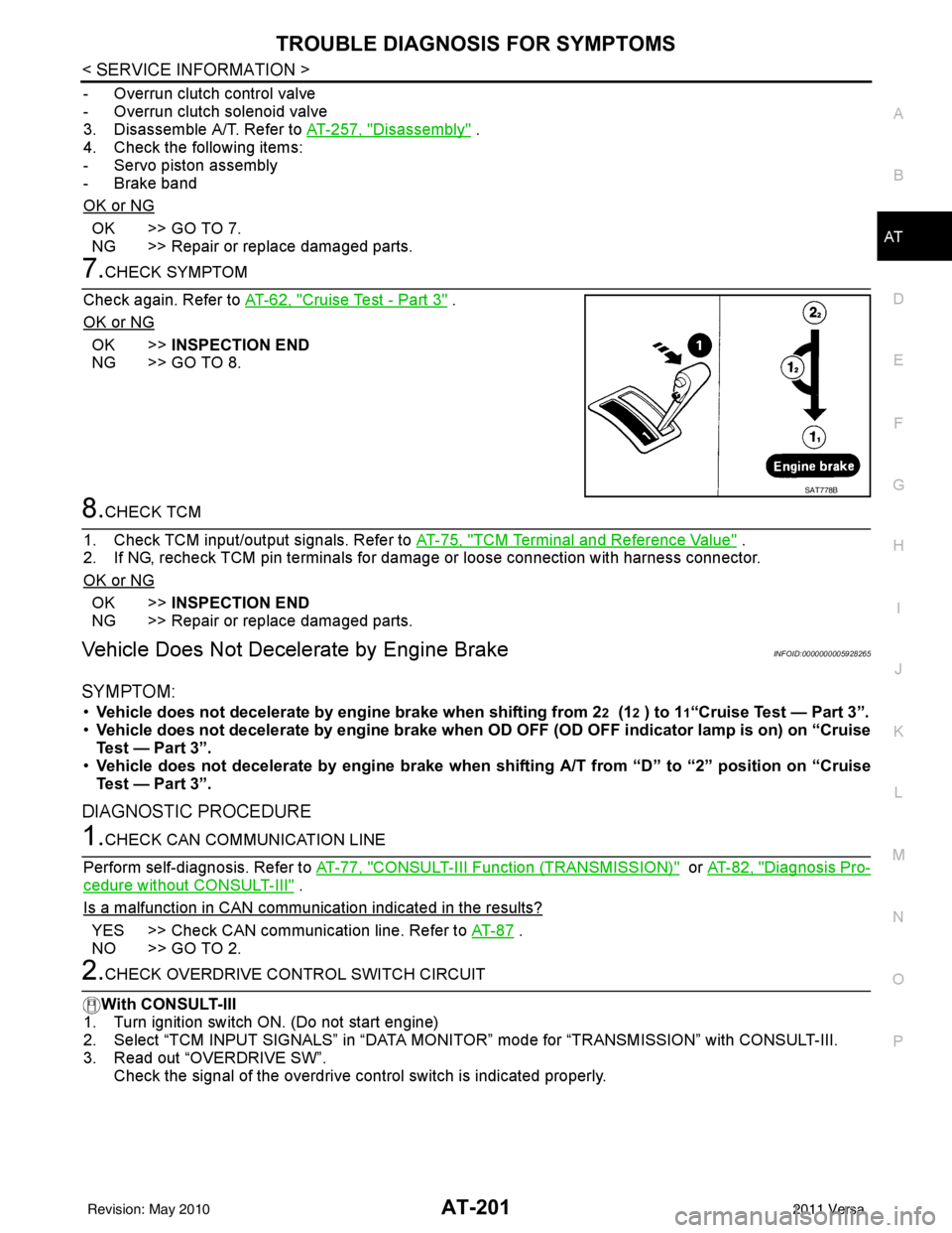
• Vehicle does not decelerate by engine brake when shifting from 22 (12 ) to 11“Cruise Test — Part 3”.
• Vehicle does not decelerate by engi ne brake when OD OFF (OD OFF indicator lamp is on) on “Cruise
Test — Part 3”.
• Vehicle does not decelerate by engi ne brake when shifting A/T from “D” to “2” position on “Cruise
Test — Part 3”.
DIAGNOSTIC PROCEDURE
1.CHECK CAN COMMUNICATION LINE
Perform self-diagnosis. Refer to AT-77, "
CONSULT-III Function (TRANSMISSION)" or AT-82, "Diagnosis Pro-
cedure without CONSULT-III" .
Is a malfunction in CAN communication indicated in the results?
YES >> Check CAN communication line. Refer to AT- 8 7 .
NO >> GO TO 2.
2.CHECK OVERDRIVE CO NTROL SWITCH CIRCUIT
With CONSULT-III
1. Turn ignition switch ON. (Do not start engine)
2. Select “TCM INPUT SIGNALS” in “DATA MONI TOR” mode for “TRANSMISSION” with CONSULT-III.
3. Read out “OVERDRIVE SW”.
Check the signal of the overdrive control switch is indicated properly.
SAT778B
Revision: May 2010 2011 Versa
Page 221 of 3787
AT-204
< SERVICE INFORMATION >
TROUBLE DIAGNOSIS FOR SYMPTOMS
- Overrun clutch solenoid valve
3. Disassemble A/T. Refer to AT-257, "
Disassembly" .
4. Check the following.
- Overrun clutch assembly. Refer to AT-307, "
Forward and Overrun Clutches" .
- Low & reverse brake assembly. Refer to AT-314, "
Low & Reverse Brake" .
OK or NG
OK >> GO TO 10.
NG >> Repair or replace damaged parts.
10.CHECK SYMPTOM
Check again. Refer to AT-62, "
Cruise Test - Part 3" .
OK or NG
OK >> INSPECTION END
NG >> GO TO 11.
11 .CHECK TCM
1. Check TCM input/output signals. Refer to AT-75, "
TCM Terminal and Reference Value" .
2. If NG, recheck TCM pin terminals for damage or loose connection with harness connector.
OK or NG
OK >> INSPECTION END
NG >> Repair or replace damaged parts.
TCM Self-Diagnosis Does Not ActivateINFOID:0000000005928266
SYMPTOM:
OD OFF indicator lamp does not come on in TCM sel f-diagnostic procedure even if the lamp circuit is
good.
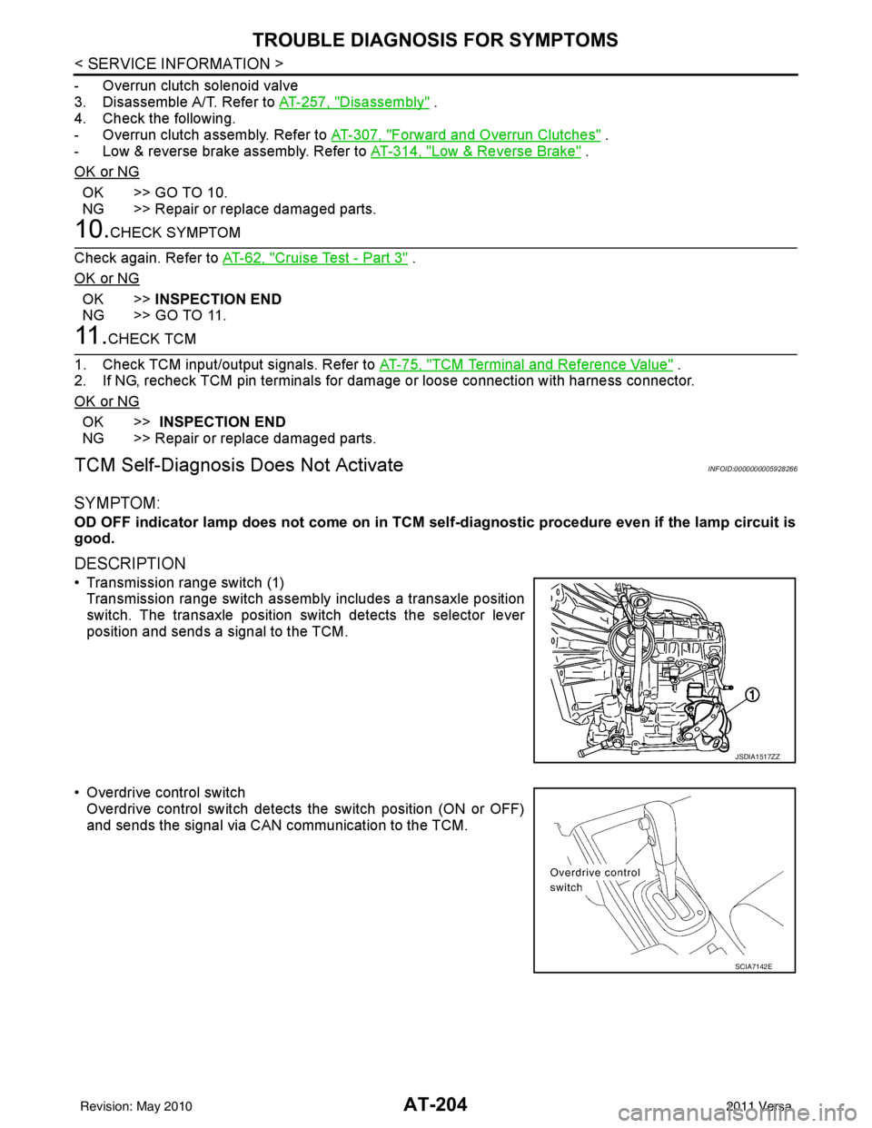
DESCRIPTION
• Transmission range switch (1) Transmission range switch assembly includes a transaxle position
switch. The transaxle position swit ch detects the selector lever
position and sends a signal to the TCM.
• Overdrive control switch Overdrive control switch detects the switch position (ON or OFF)
and sends the signal via CAN communication to the TCM.
JSDIA1517ZZ
SCIA7142E
Revision: May 2010 2011 Versa
Page 239 of 3787
AT-222
< SERVICE INFORMATION >
ON-VEHICLE SERVICE
ON-VEHICLE SERVICE
Control Valve Assembly and AccumulatorsINFOID:0000000005928278
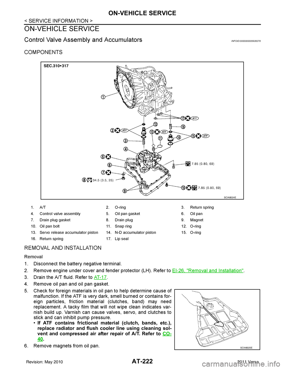
COMPONENTS
REMOVAL AND INSTALLATION
Removal
1. Disconnect the battery negative terminal.
2. Remove engine under cover and fender protector (LH). Refer to EI-26, "
Removal and Installation".
3. Drain the A/T fluid. Refer to AT- 1 7
.
4. Remove oil pan and oil pan gasket.
5. Check for foreign materials in oil pan to help determine cause of malfunction. If the ATF is very dark, smell burned or contains for-
eign particles, friction material (clutches, band) may need
replacement. A tacky film that will not wipe clean indicates var-
nish build up. Varnish can cause valves, servo, and clutches to
stick and can inhibit pump pressure.
•If ATF contains frictional ma terial (clutch, bands, etc.),
replace radiator and flush cool er line using cleaning sol-
vent and compressed air after repair of A/T. Refer to CO-
40.
6. Remove magnets from oil pan.
1. A/T 2. O-ring 3. Return spring
4. Control valve assembly 5. Oil pan gasket6. Oil pan
7. Drain plug gasket 8. Drain plug9. Magnet
10. Oil pan bolt 11. Snap ring 12. O-ring
13. Servo release accumulator piston 14. N-D accumulator piston 15. O-ring
16. Return spring 17. Lip seal
SCIA8024E
SCIA8025E
Revision: May 2010 2011 Versa