2011 MITSUBISHI L200 ECO mode
[x] Cancel search: ECO modePage 45 of 330

lIf the sunroof does not operate when the sun-
roof switch is operated, release the switch
and check whether something is trapped by
the sunroof. If nothing is trapped, we recom-
mend you to have the sunroof checked.
l Depending on the model of ski carriers or
roof carriers, the sunroof may make contact
with the carrier when the sunroof is tilted up.
Be careful when tilting up the sunroof if such
a ski carrier or a roof carrier is installed.
l Be sure to close the sunroof completely
when washing the vehicle or when leaving
the vehicle.
l Be careful, not to put any wax on the weath-
erstrip (black rubber) around the sunroof
opening. If stained with wax, the weather-
strip cannot maintain a weatherproof seal
with the sunroof.
l After washing the vehicle or after it has
rained, wipe off any water that is on the sun-
roof before operating it.
l Operating the sunroof repeatedly with the en-
gine stationary will run down the battery. Op-
erate the sunroof while the engine is running.
Locking and unlocking
1-15
1
Page 73 of 330
Seat belt inspectionE00406300475
l Check the belts for cuts, worn or frayed web-
bing and for cracked or deformed metallic
parts. Replace the belt assembly if defective.
l A dirty belt should be cleaned with neutral de-
tergent in warm water. After rinsing in water,
let it dry in the shade. Do not attempt to
bleach or re-dye the belts because this affects
their characteristics.WARNINGl We recommend you have all seat belt as-
semblies including retractors and attach-
ing hardware inspected after any colli-
sion. We recommend that seat belt assem-
blies in use during a collision be replaced
unless the collision was minor and the
belts show no damage and continue to op-
erate properly.
l Do not attempt to repair or replace any
part of the seat belt assemblies; we recom-
mend you to have this work done by a
MITSUBISHI MOTORS Authorized
Service Point. Incorrect repair or replace-
ment could reduce the effectiveness of the
belts and could result in serious injury in
the event of a collision.
l Once the pretensioner has activated, it
cannot be re-used.
It must be replaced together with the re-
tractor.Supplemental restraint system
(SRS) - airbag* E00407201797
The information written in this Supplemental Re-
straint System (SRS) section contains important
points concerning the driver, front passenger, side
and curtain airbags.
The SRS driver and front passenger airbags are de-
signed to supplement the primary protection of the
driver and front passenger side seat belt systems by
providing those occupants with protection against
head and chest injuries in certain moderate-to-se-
vere frontal collisions.
The SRS side airbag is designed to supplement the
properly worn seat belts and provide the driver and
front passenger with protection against chest injury
in certain moderate-to-severe side impact collisions.
The SRS curtain airbags are designed to supple-
ment the properly worn seat belts and provide the
driver and passengers with protection against head
injuries in certain moderate-to-severe side impact
collisions.
The SRS is NOT a substitute for the seat belts; for
maximum protection in all types of crashes and ac-
cidents, seat belts should ALWAYS be worn by ev-
eryone who drives or rides in this vehicle.WARNINGl IT IS VERY IMPORTANT TO AL-
WAYS PROPERLY WEAR YOUR
SEAT BELT, EVEN WITH AN AIRBAG:WARNING• Seat belts help keep the driver and pas-
sengers properly positioned, which re-
duces injury risk in all collisions, and
reduces the risk of serious or fatal in-
juries when the airbags inflate.
During sudden braking just before a
collision, an unrestrained or improper-
ly restrained driver or passengers can
move forward into direct contact with
or within close proximity to the airbag
which may then deploy during the col-
lision.
The initial stage of airbag inflation is
the most forceful which could cause se-
rious or fatal injuries if the occupant
contacts it at this stage.
• Seat belts reduce the risk of injury in
roll-overs, rear impact collisions, and
in lower-speed frontal collisions, be-
cause driver’s and passenger’s air-
bags are not designed to inflate in
those situations.
• Seat belts reduce the risk of being
thrown from your vehicle in a colli-
sion or roll-over.
l IT IS VERY IMPORTANT TO BE PROP-
ERLY SEATED.
A driver or front passenger too close to
the steering wheel or instrument panel
during airbag deployment can be killed
or seriously injured.
Airbags inflate very fast, and with great
force.
If the driver and front passenger are not
properly seated and restrained, the air-
Seat and seat belts
2-27
2
Page 81 of 330

WARNINGlRight after the airbag inflation, several
airbag system components will be hot. Do
not touch them; you could be burned.
l The airbag system is designed to work on-
ly once. Once the airbags have deployed,
they will not work again. They must
promptly be replaced, and we recom-
mend you to have the entire airbag sys-
tem inspected by a MITSUBISHI
MOTORS Authorized Service Point.Side airbag system E00407600374
The side airbags (A) are contained in the driver and
front passenger seatbacks.
The side airbag is designed to inflate only on the
side of the vehicle that is impacted, even with no
passenger in the front seat.
The label shown here is attached to the seatbacks
with a side airbag.Curtain airbag system E00409100474
The curtain airbags are contained in the front pil-
lars and roof side rail. The curtain airbag is de-
signed to inflate only on the side of the vehicle that
is impacted, even with no passenger in the front
seat or rear seat.
Deployment of side airbags and cur-
tain airbags E00407701011
The side airbags and curtain airbags ARE DE-
SIGNED TO DEPLOY when…
The side airbags and curtain airbags are designed
to deploy when the vehicle suffers a moderate-to-
severe side impact to the middle of the passenger
compartment.
The typical condition is shown in the illustration.
The seat belts in your vehicle are your primary
means of protection in a collision. The SRS side air-
bags and curtain airbags are designed to provide ad-
ditional protection. Therefore, for your safety and
the safety of all occupants, be sure to always prop-
erly wear your seat belts.
Seat and seat belts
2-35
2
Page 100 of 330
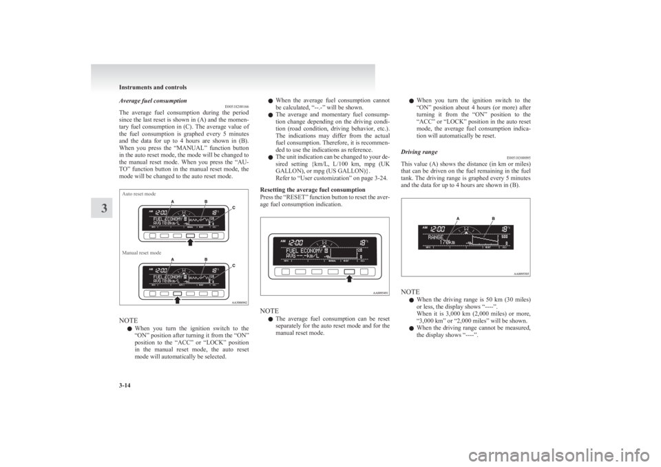
Average fuel consumptionE00518200166
The average fuel consumption during the period
since the last reset is shown in (A) and the momen-
tary fuel consumption in (C). The average value of
the fuel consumption is graphed every 5 minutes
and the data for up to 4 hours are shown in (B).
When you press the “MANUAL” function button
in the auto reset mode, the mode will be changed to
the manual reset mode. When you press the “AU-
TO” function button in the manual reset mode, the
mode will be changed to the auto reset mode.Auto reset modeManual reset mode
NOTE
l When you turn the ignition switch to the
“ON” position after turning it from the “ON”
position to the “ACC” or “LOCK” position
in the manual reset mode, the auto reset
mode will automatically be selected.
l When the average fuel consumption cannot
be calculated, “--.-” will be shown.
l The average and momentary fuel consump-
tion change depending on the driving condi-
tion (road condition, driving behavior, etc.).
The indications may differ from the actual
fuel consumption. Therefore, it is recommen-
ded to use the indications as reference.
l The unit indication can be changed to your de-
sired setting {km/L, L/100 km, mpg (UK
GALLON), or mpg (US GALLON)}.
Refer to “User customization” on page 3-24.
Resetting the average fuel consumption
Press the “RESET” function button to reset the aver-
age fuel consumption indication.
NOTE
l The average fuel consumption can be reset
separately for the auto reset mode and for the
manual reset mode.
l When you turn the ignition switch to the
“ON” position about 4 hours (or more) after
turning it from the “ON” position to the
“ACC” or “LOCK” position in the auto reset
mode, the average fuel consumption indica-
tion will automatically be reset.Driving range E00518300095
This value (A) shows the distance (in km or miles)
that can be driven on the fuel remaining in the fuel
tank. The driving range is graphed every 5 minutes
and the data for up to 4 hours are shown in (B).
NOTE
l When the driving range is 50 km
(30 miles)
or less, the display shows “----”.
When it is 3,000 km (2,000 miles) or more,
“3,000 km” or “2,000 miles” will be shown.
l When the driving range cannot be measured,
the display shows “----”.
Instruments and controls
3-14
3
Page 101 of 330
lThe driving range is shown based on the ac-
cumulated fuel consumption data, however,
may be changed depending on the driving con-
dition (road condition, driving behavior,
etc.). If the battery terminals are disconnec-
ted, the accumulated fuel consumption data
will be erased. It is recommended to use the
indication as reference.
l When the vehicle is fueled, the driving range
will be updated. However, if the amount of
fueling is small, the indication may not be cor-
rect. Therefore, fill up the tank as much as
possible in case of fueling.
l When the vehicle is stopped on a steep slope,
the value of the driving range may increase.
This is caused by the fuel movement inside
the tank on the slope and is not deemed as a
failure.
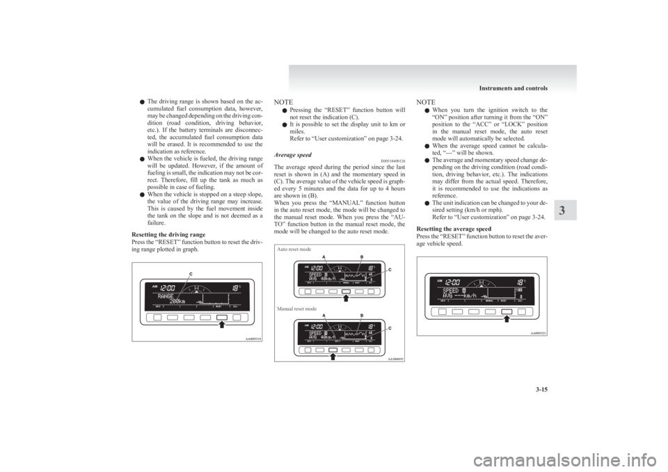
Resetting the driving range
Press the “RESET” function button to reset the driv-
ing range plotted in graph.NOTE
l Pressing the “RESET” function button will
not reset the indication (C).
l It is possible to set the display unit to km or
miles.
Refer to “User customization” on page 3-24.Average speed E00518400126
The average speed during the period since the last
reset is shown in (A) and the momentary speed in
(C). The average value of the vehicle speed is graph-
ed every 5 minutes and the data for up to 4 hours
are shown in (B).
When you press the “MANUAL” function button
in the auto reset mode, the mode will be changed to
the manual reset mode. When you press the “AU-
TO” function button in the manual reset mode, the
mode will be changed to the auto reset mode.
Auto reset modeManual reset modeNOTE
l When you turn the ignition switch to the
“ON” position after turning it from the “ON”
position to the “ACC” or “LOCK” position
in the manual reset mode, the auto reset
mode will automatically be selected.
l When the average speed cannot be calcula-
ted, “---” will be shown.
l The average and momentary speed change de-
pending on the driving condition (road condi-
tion, driving behavior, etc.). The indications
may differ from the actual speed. Therefore,
it is recommended to use the indications as
reference.
l The unit indication can be changed to your de-
sired setting (km/h or mph).
Refer to “User customization” on page 3-24.
Resetting the average speed
Press the “RESET” function button to reset the aver-
age vehicle speed.
Instruments and controls
3-15
3
Page 102 of 330
NOTEl The average speed can be reset separately for
the auto reset mode and for the manual reset
mode.
l When you turn the ignition switch to the
“ON” position about 4 hours (or more) after
turning it from the “ON” position to the
“ACC” or “LOCK” position in the auto reset
mode, the average speed indication will auto-
matically be reset.Outside temperature E00518500097
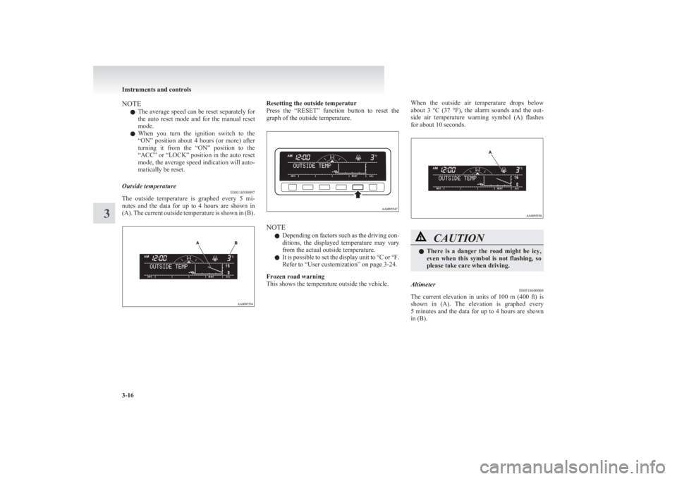
The outside temperature is graphed every 5 mi-
nutes and the data for up to 4 hours are shown in
(A). The current outside temperature is shown in (B).
Resetting the outside temperatur
Press the “RESET” function button to reset the
graph of the outside temperature.
NOTE
l Depending on factors such as the driving con-
ditions, the displayed temperature may vary
from the actual outside temperature.
l It is possible to set the display unit to °C or °F.
Refer to “User customization” on page 3-24.
Frozen road warning
This shows the temperature outside the vehicle.
When the outside air temperature drops below
about 3 °C (37 °F), the alarm sounds and the out-
side air temperature warning symbol (A) flashes
for about 10 seconds.CAUTIONl There is a danger the road might be icy,
even when this symbol is not flashing, so
please take care when driving.Altimeter E00518600069
The current elevation in units of 100 m (400 ft) is
shown in (A). The elevation is graphed every
5 minutes and the data for up to 4 hours are shown
in (B).
Instruments and controls
3-16
3
Page 127 of 330

Economical driving.......................................................................4-02
Driving, alcohol and drugs ........................................................... 4-02
Safe driving techniques ................................................................ 4-03
Running-in recommendations.......................................................4-04
Parking brake ................................................................................ 4-07
Parking .......................................................................................... 4-08
Steering wheel height adjustment .................................................4-09
Inside rear-view mirror ................................................................. 4-09
Outside rear-view mirrors ............................................................. 4-10
Ignition switch .............................................................................. 4-11
Steering wheel lock ...................................................................... 4-12
Starting..........................................................................................4-13
Manual transmission ..................................................................... 4-14
Automatic transmission 4A/T ....................................................... 4-16
Automatic transmission Sports Mode 5A/T .................................4-20
Easy select 4WD* ......................................................................... 4-25
Super select 4WD* ....................................................................... 4-29
Rear differential lock* .................................................................. 4-34
4-wheel drive operation ................................................................ 4-38
Inspection and maintenance following rough road oper- ation .......................................................................................... 4-40
Cautions on handling of 4-wheel drive vehicles ..........................4-40
Limited-slip differential* .............................................................. 4-42
Braking ......................................................................................... 4-42
Anti-lock brake system (ABS)* ................................................... 4-43
Power steering system .................................................................. 4-45
Active Stability & Traction Control (ASTC)* .............................4-46
Cruise control* ............................................................................. 4-48
Cargo loads ................................................................................... 4-52
Trailer towing ............................................................................... 4-53Starting and driving4
Page 140 of 330
lWhen the engine has not been started within
about 5 seconds after the diesel preheat indi-
cation lamp went out, return the ignition key
to the “LOCK” position. Then, turn the key
to the “ON” position to preheat the engine
again.
l When the engine is warm, the diesel preheat
indication lamp does not come on even if the
ignition key is placed in the “ON” position.
Start the engine by turning the ignition key
right to the “START” position.
6. Operate the accelerator pedal as described be-
low in accordance with the atmospheric tem-
perature and/or engine condition and then
start the engine.
l When the atmospheric temperature is
moderate or the engine is warm, start the
engine without depressing the accelerator
pedal.
l When the atmospheric temperature is low
and the engine is cold, start the engine
while depressing the accelerator pedal.Fuel injection amount learning process E00616000028
To keep exhaust emissions and engine noise low,
the engine very occasionally performs a learning
process for the fuel injection amount.
The engine sounds slightly different from usual
while the learning process is taking place. The
change in the engine sound does not indicate a fault.
Manual transmission E00602000199
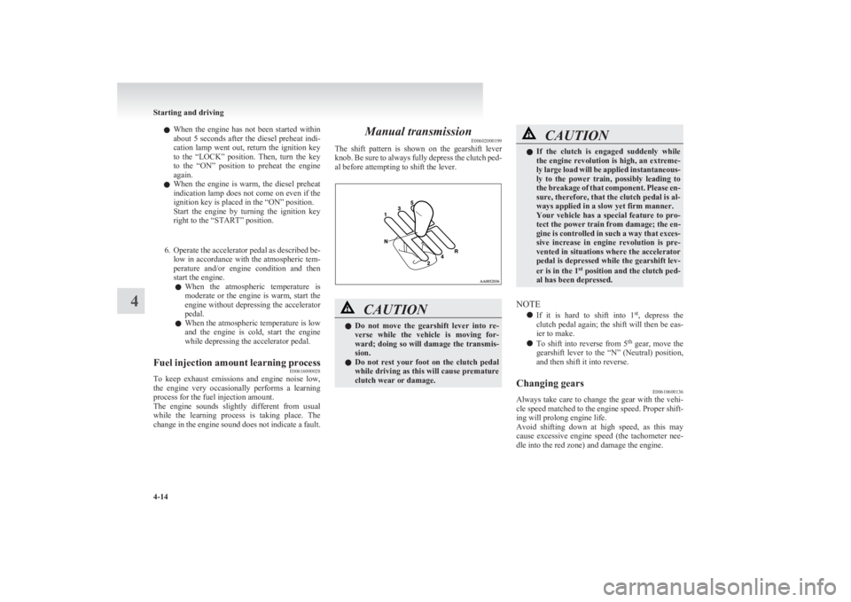
The shift pattern is shown on the gearshift lever
knob. Be sure to always fully depress the clutch ped-
al before attempting to shift the lever.CAUTIONl Do not move the gearshift lever into re-
verse while the vehicle is moving for-
ward; doing so will damage the transmis-
sion.
l Do not rest your foot on the clutch pedal
while driving as this will cause premature
clutch wear or damage.CAUTIONl If the clutch is engaged suddenly while
the engine revolution is high, an extreme-
ly large load will be applied instantaneous-
ly to the power train, possibly leading to
the breakage of that component. Please en-
sure, therefore, that the clutch pedal is al-
ways applied in a slow yet firm manner.
Your vehicle has a special feature to pro-
tect the power train from damage; the en-
gine is controlled in such a way that exces-
sive increase in engine revolution is pre-
vented in situations where the accelerator
pedal is depressed while the gearshift lev-
er is in the 1 st
position and the clutch ped-
al has been depressed.
NOTE
l If it is hard to shift into 1 st
, depress the
clutch pedal again; the shift will then be eas-
ier to make.
l To shift into reverse from
5th
gear, move the
gearshift lever to the “N” (Neutral) position,
and then shift it into reverse.
Changing gears E00610600136
Always take care to change the gear with the vehi-
cle speed matched to the engine speed. Proper shift-
ing will prolong engine life.
Avoid shifting down at high speed, as this may
cause excessive engine speed (the tachometer nee-
dle into the red zone) and damage the engine.
Starting and driving
4-14
4