2011 MERCEDES-BENZ C-CLASS COUPE fuel cap
[x] Cancel search: fuel capPage 15 of 373
F
Fatigue Assist see ATTENTION ASSIST
Fault message
see Display messages
Filler cap
see Fuel fille rflap
Fire extinguisher ............................... 315
First-aid kit ......................................... 314
Flat tyre Changing a wheel/fitting the
spare wheel ................................... 321
MOExtended run-fla tsystem ......... 324
Preparing the vehicle .....................316
Raising the vehicle .........................322
TIREFIT kit ...................................... 317
Floormat ............................................ .297
Foglamps Extended range .............................. 112
Switching on/off ........................... 109
Frequencies
Garage door opene r....................... 297
Mobile phone ................................. 351
Two-way radio ................................ 351
Fron tfoglamp
Display message (12-butto nmul-
tifunction steering wheel) ..............249
Front foglamps
Display message (4-button multi-
function steering wheel) ................246
Switching on/off ........................... 109
Fron twindscreen
see Windscreen
Fuel
Displaying the range (12-button
multifunction steering wheel) ........215
Displaying the range (4-button
multifunctio nsteering wheel) ........210
Important safety notes ..................354
Notes about consumption .............354
Problem (malfunction) ...................157
Refuelling ...................................... .152
Tank content/reserve fuel .............354
Tank content display (12-button
multifunctio nsteering wheel) ..........35
Tank content display (4-button
multifunctio nsteering wheel) ..........32Fuel consumption
Current (12-button multifunction
steering wheel) .............................. 215
Fuel filler flap
Opening/closing ............................ 155
Fuel filter
Display message (12-button mul-
tifunctio nsteering wheel) ..............255
Display message (4-button multi-
function steering wheel) ................253
Fuel reserve
Display message (12-button mul-
tifunctio nsteering wheel) ..............255
Display message (4-button multi-
function steering wheel) ................253
see Fuel
Fuel tank
Capacity ........................................ 354
Problem (malfunction) ...................157
Fuse allocation chart (vehicle tool
kit) ...................................................... 315
Fuses Allocation chart ............................. 334
Before changing ............................. 334
Fuse box in the boot ......................334
Fuse box in the engine compart-
ment .............................................. 334
Important safety notes ..................333 G
Garage door opener Clearing the memory .....................296
Frequencies ................................... 297
Notes ............................................. 294
Opening/closing the garage door ..295
Programming (button in the rear-
view mirror) ................................... 294
Gear indicator (12-button multi-
function steering wheel) ..................229
Gearshift program SETUP (on-board computer) ..........229
Genuine Mercedes-Benz parts .........350
Glove compartment ..........................28512
Index
Page 158 of 373
Flow improver
Flow improvers can be added to improve the
cold resistance of diesel fuel .The effective-
ness of a flow improver is not guaranteed with
every fuel.
Correct dosage and thorough mixing are deci-
sive factors in ensuring improvement in low-
temperature resistance. Under certain cir-
cumstances, an excessive dosage may
actually decrease low-temperature resist-
ance and should therefore be avoided. Follow
the manufacturer's dosing instructions.
Mix the additive with the diesel in good time,
before the flow properties of the diesel
become inadequate. Malfunctions can other-
wise only be rectified by heating the entire
fuel system, e.g. by parking the vehicle in a
heated garage.
Observe the information provided by the man-
ufacturer when using a flow improver. Only
use flow improvers that have been tested and
approved by Mercedes-Benz. You can obtain
further information from any Mercedes-Benz
Service Centre. Refuelling
Fuel filler flap The fuel filler flap is unlocked or locked auto-
matically when you open or close the vehicle
with the key or using KEYLESS-GO.
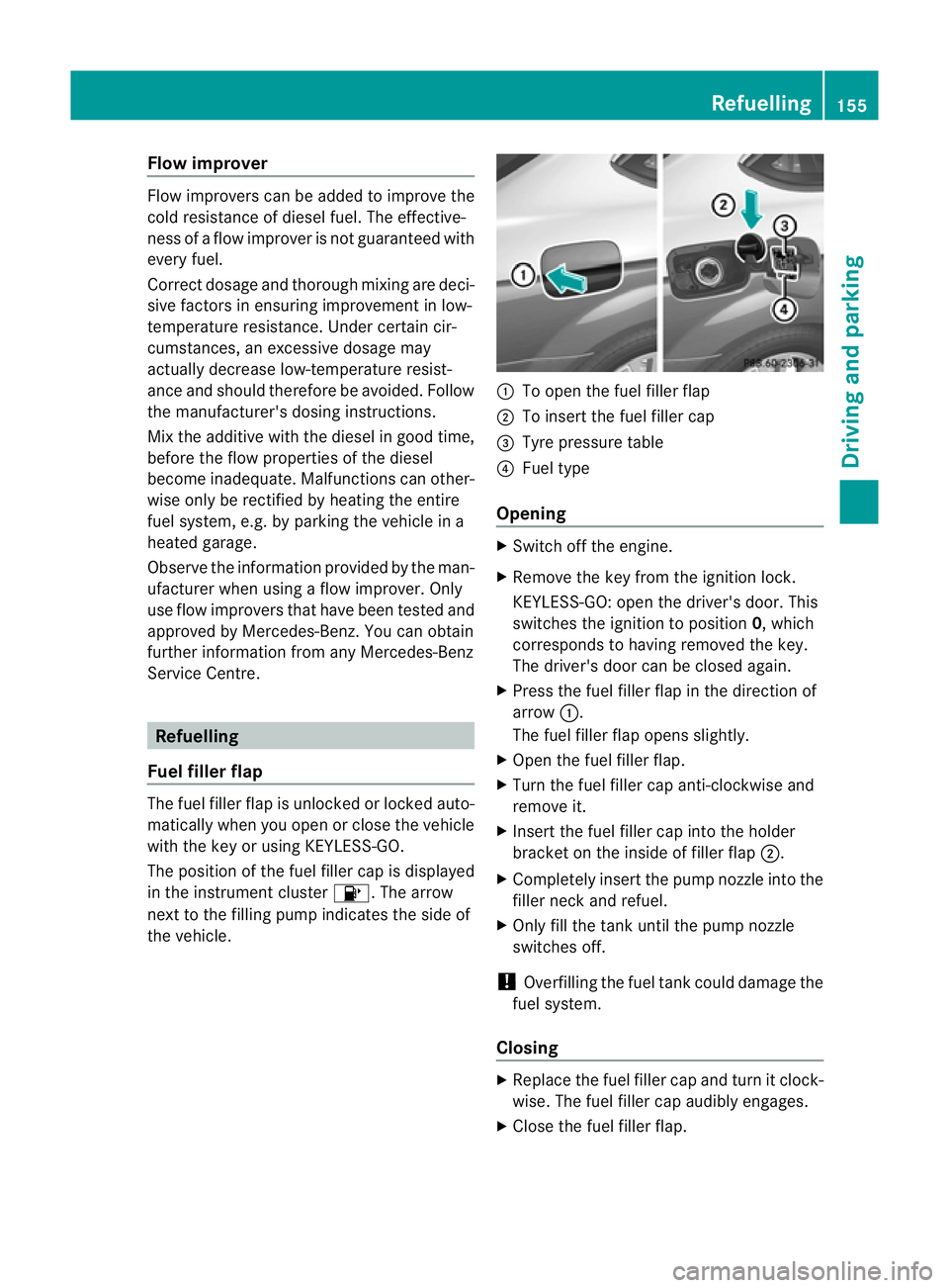
The position of the fuel filler cap is displayed
in the instrument cluster 8.The arrow
next to the filling pump indicates the side of
the vehicle. :
To open the fuel filler flap
; To insert the fuel filler cap
= Tyre pressure table
? Fuel type
Opening X
Switch off the engine.
X Remove the key from the ignition lock.
KEYLESS-GO: open the driver's door. This
switches the ignition to position 0, which
corresponds to having removed the key.
The driver's door can be closed again.
X Press the fuel filler flap in the direction of
arrow :.
The fuel filler flap opens slightly.
X Open the fuel filler flap.
X Turn the fuel filler cap anti-clockwise and
remove it.
X Insert the fuel filler cap into the holder
bracket on the inside of filler flap ;.
X Completely insert the pump nozzle into the
filler neck and refuel.
X Only fill the tank until the pump nozzle
switches off.
! Overfilling the fuel tank could damage the
fuel system.
Closing X
Replace the fuel filler cap and turn it clock-
wise. The fuel filler cap audibly engages.
X Close the fuel filler flap. Refuelling
155Driving and parking Z
Page 203 of 373

G
WARNING
If the Check trailer hitch locking mechanism message appears in the multi-
function display while the vehicle is in motion,
pull over immediately and check whethe rthe
ball coupling is correctly engaged. G
WARNING
Always observe the maximum speed permit-
ted in Germany for vehicle/trailer combina-
tions, even in countries where higher speeds
are permitted. This lowers the risk of an acci-
dent. G
WARNING
Never depress the brake pedal continuously
while the vehicle is in motion, e.g. never cause
the brakes to rub by applying constant slight
pedal pressure. This causes the brake system
to overheat, increases the braking distance
and can lead to the brakes failing completely. G
WARNING
On no account should you attempt to draw the
vehicle/trailer combination out by increasing
speed.
General information i
When towing a trailer, set the tyre pres-
sure on the rear axle of the towing vehicle
for a maximum load; see the tyre pressure
table in the fuel filler flap (Y page 339).
You will find installation dimensions and loads
in the "Technical data" section
(Y page 361).
The maximum permissible trailer drawbar
noseweight on the ball coupling is 75 kg.
However, the actual noseweight must not
exceed the value given on the trailer tow hitch
and trailer identification plates. The lowest
weight applies.
! Use a noseweight as close as possible to
the maximum permissible noseweight. Do
not use a noseweight of less than 50 kg,
otherwise the trailer may come loose. Bear in mind that the payload and the rear
axle load are reduced by the actual nose-
weight.
Please note that when towing a trailer, PARK-
TRONIC (Y page 179), parking guidance
(Y page 183) and Blind Spot Assist
(Y page 190) are only available with limita-
tions, or not at all.
i The height of the ball coupling changes
with the load of the vehicle. If necessary,
use a trailer with a height-adjustable draw-
bar.
Driving tips i
Observe the notes on ESP ®
trailer stabi-
lisation (Y page 70).
In Germany, the maximum permissible speed
for vehicle/trailer combinations depends on
the type of trailer, and is either 80 km/h or
100 km/h. In some countries, higher maxi-
mum speeds are permissible for vehicle/
trailer combinations. Before beginning the
journey, check the trailer's documents to see
what the maximum permitted speed is.
For certain Mercedes-Ben zvehicles, the max-
imum permissible rear axle load is increased
when towing a trailer. Refer to the "Technical
data" section to find out whether this applies
to your vehicle. If you utilise any of the added
maximum rear axle load when towing a trailer,
the vehicle/trailer combination may not
exceed a maximum speed of 100 km/h for
reasons concerning the operating permit.
This also applies in countries in which the
permissible maximum speed for vehicle/
trailer combinations is above 100 km/h.
When towing a trailer, your vehicle's handling
characteristics will be differen tincomparison
to when driving without a trailer.
The vehicle/trailer combination:
R is heavier
R is restricted in its acceleration and gradi-
ent-climbing capability
R has an increased braking distance 200
Trailer towingDriving and parking
Page 204 of 373
R
is affected more by strong crosswinds
R demands more sensitive steering
R consumes more fuel
On long and steep downhill gradients, you
must shift to a lower gear in good time, or on
vehicles with automatic transmission, select
the shift range 1,2or 3.
i This also applies if you have activated
cruise control, SPEEDTRONIC or DIS-
TRONIC PLUS.
This will use the braking effect of the engine,
so less braking will be required to maintain
the speed. This relieves the load on the brake
system and prevents the brakes from over-
heating and wearing too quickly. If you need
additional braking, depress the brake pedal
repeatedly rather than continuously.
Driving tips R
Maintain a greater distanc efrom the vehi-
cle in front than when driving without a
trailer.
R Avoid braking abruptly .Ifpossible, brake
gently at first to allow the trailer to run on.
Then, increase the braking force rapidly.
R The values given for gradient-climbing
capabilities from a standstill refer to sea
level. When driving in mountainous areas,
note that the power output of the engine,
and consequently the vehicle's gradient-
climbing capability, decrease with increas-
ing altitude.
If the trailer swings from side to side:
X Do not accelerate.
X Do not counter-steer.
X Brake if necessary. Folding out the ball coupling
Before you can tow a trailer with your vehicle,
you must fold out the ball coupling.
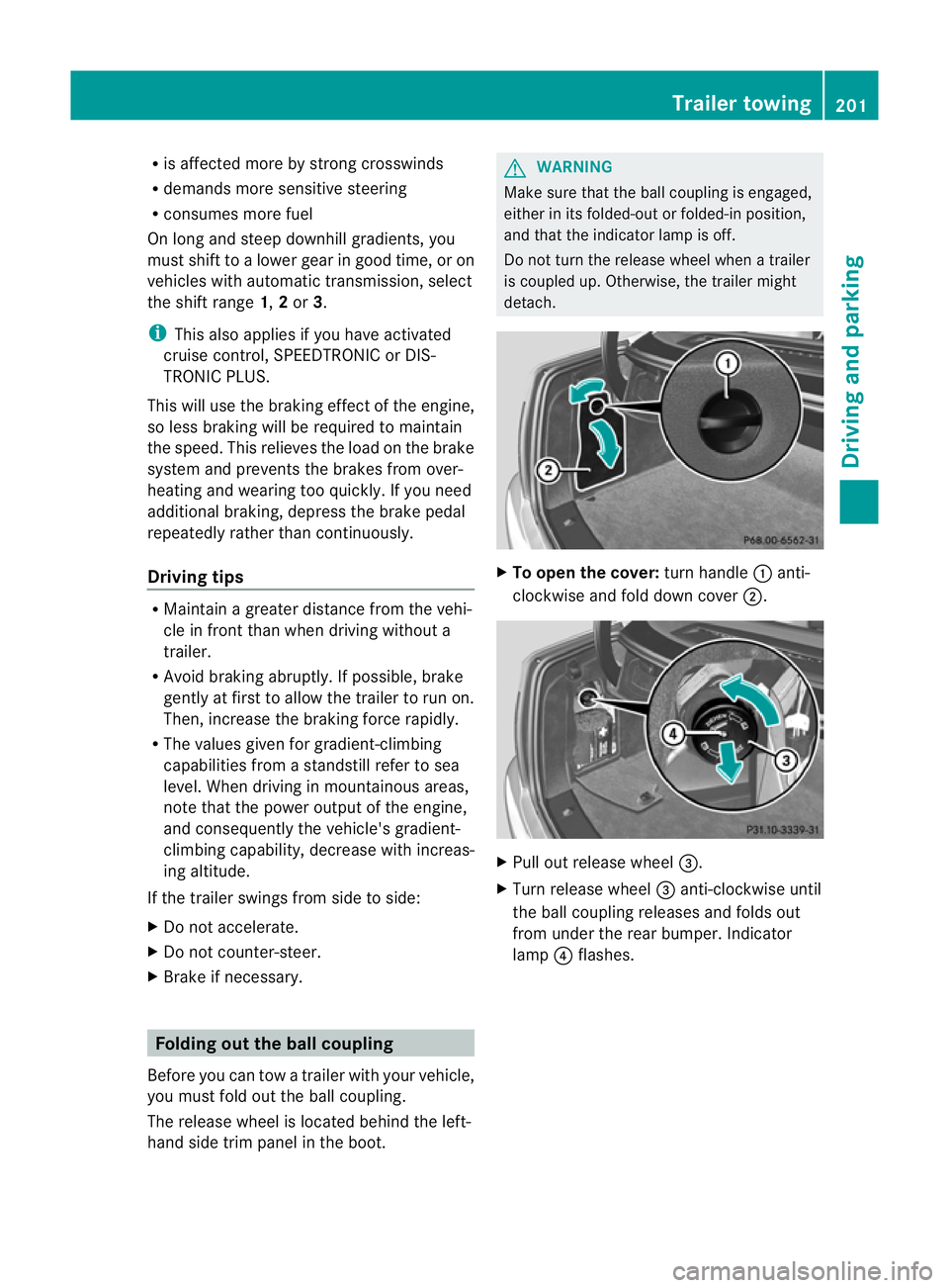
The release wheel is located behind the left-
hand side trim panel in the boot. G
WARNING
Make sure that the ball coupling is engaged,
either in its folded-out or folded-in position,
and that the indicator lamp is off.
Do not turn the release wheel when a trailer
is coupled up. Otherwise, the trailer might
detach. X
To open the cover: turn handle:anti-
clockwise and fold down cover ;. X
Pull out release wheel =.
X Turn release wheel =anti-clockwise until
the ball coupling releases and folds out
from under the rear bumper. Indicator
lamp ?flashes. Trailer towing
201Driving and parking Z
Page 323 of 373
the work required. Mercedes-Benz recom-
mends tha tyou use a Mercedes-Benz Service
Centre for this purpose. In particular, work
relevant to safety or on safety-related sys-
tems must be carried out at a qualified spe-
cialist workshop.
Tyre pressure of 180 kPa (1.8 bar/
26 psi) is reached X
Switch off the tyre inflation compressor.
X Unscrew the filler hose from the valve of
the faulty tyre.
! After use, excess TIREFIT may run out of
the filler hose. This may cause stains.
Therefore, place the filler hose in the plastic
bag which contained the TIREFIT kit.
X Stow the tyre sealant bottle, the tyre infla-
tion compressor and the warning triangle.
X Pull away immediately. G
WARNING
Do not exceed the maximum speed of
80 km/h.
The "max. 80 km/h" label must be affixed in
the driver's field of vision.
The vehicle's handling characteristics may be
affected.
X Stop after driving for approximately ten
minutes and check the tyre pressure with
the tyre inflation compressor. G
WARNING
If the tyre pressure is less than 130 kPa
(1.3 bar/20 psi), the tyre is too severely dam-
aged. Do not drive any further. Consult a
qualified specialist workshop which has the
necessary specialist knowledge and tools to
carry out the work required. Mercedes-Benz
recommends that you use aMercedes-Benz
Service Centre for this purpose. In particular,
work relevant to safety or on safety-related
systems must be carried out at a qualified
specialist workshop. X
Correct the tyre pressure if it is still at least
130 kPa (1.3 bar/20 psi) (for the values,
see the fuel filler flap).
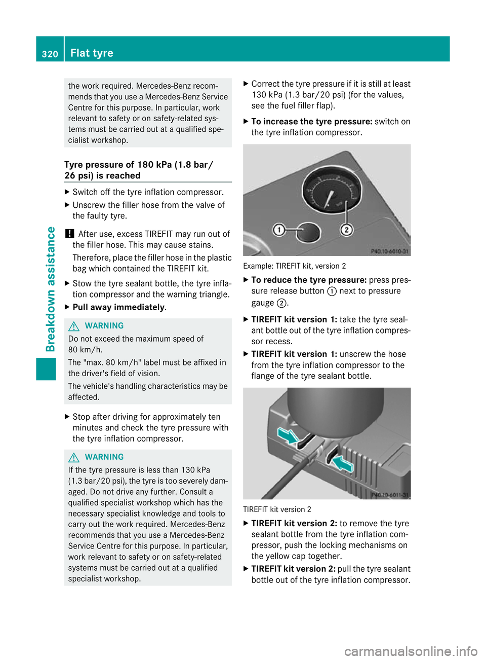
X To increase the tyre pressure: switch on
the tyre inflation compressor. Example: TIREFIT kit, version 2
X
To reduce the tyre pressure: press pres-
sure release button :next to pressure
gauge ;.
X TIREFIT kit version 1: take the tyre seal-
ant bottle out of the tyre inflation compres-
sor recess.
X TIREFIT kit version 1: unscrew the hose
from the tyre inflation compressor to the
flange of the tyre sealant bottle. TIREFIT kit version 2
X
TIREFIT kit version 2: to remove the tyre
sealant bottle from the tyre inflation com-
pressor, push the locking mechanisms on
the yellow cap together.
X TIREFIT kit version 2: pull the tyre sealant
bottle out of the tyre inflation compressor. 320
Flat tyreBreakdown assistance
Page 332 of 373

Jump-starting
G
WARNING
There is a risk of acid burns when jump-starting a vehicle due to the gases which escape from
the battery. Do not lean over the battery while the engine is being jump-started. G
WARNING
Gases escaping from the battery during jump-starting may cause minor explosions. Avoid cre-
ating sparks. Keep naked flames away from the battery, and do not smoke.
Comply with safety precautions when handling batteries. You will find these under "Battery" in
the index.
! Avoid repeated and lengthy starting attempts. Otherwise, non-combusted fuel may dam-
age the catalytic converter 13
and create a risk of fire.
Do not use a rapid-charging device to start the engine.
Make sure the jump leads are not damaged.
Make sure the jump leads are not touching any other metal objects when they are connected
to the battery.
If your vehicle's battery is discharged, the engine can be jump-started from another vehicle
or from a second battery using jump leads.
Observe the following points:
X The battery is not accessible in all vehicles. If the other vehicle's battery is not accessible,
jump-start the vehicle using a second battery or ajump-starting device.
X Only jump-start the vehicle when the engine is cold and the catalyti cconverter system has
cooled down 14
.
X Do not start the engine if the battery is frozen. Let the battery thaw first.
X Jump-starting may only be performed from batteries with a nominal voltage of 12 V.
X Only use jump leads which have a sufficient cross-section and insulated terminal clamps.
X Make sure that the jump leads cannot come into contact with parts, such as the pulley or
the fan. These parts move when the engine is started and while it is running.
X If the battery is fully discharged, leave the battery that is being used to jump-start connected
for a few minutes before attempting to start.T his charges the empty battery a little.
i Jump leads and further information about jump-starting can be obtained from any
Mercedes-Benz Service Centre, for example.
X Make sure that the two vehicles do not touch.
X Apply the parking brake firmly.
X Manual transmission: engage neutral.
X Automatic transmission: move the selector lever toP.
X Switch off all electrical consumers (e.g. radio, blower, etc.).
X Open the bonnet (Y page 301).
13 Only vehicles with a petrol engine.
14 Only vehicles with a petrol engine. Jump-starting
329Breakdown assistance Z
Page 342 of 373

Tyre pressure
Tyre pressure specifications
You will find a table of tyre pressures for var-
ious operating conditions on the inside of
your vehicle's fuel fille rflap.
Operation with emergency spare wheel:
The applicable value for the emergency spare
wheel is stated on the spare wheel and in the
technical data section.
Operation with a trailer: The applicable
value for the rear tyres is the maximum tyre
pressure value stated on the table inside the
fuel filler flap.
The table inside the fuel filler flap may state
tyre pressures for differen tload conditions.
These are defined in the table as different
numbers of passengers and amounts of lug-
gage. The actual number of seats may vary –
for more information please refer to the vehi-
cle's registration documents.
If no other data is stated, the tyre pressures
specified on the fuel filler flap apply for all
tyres approved for this vehicle. If a tyre size precedes a tyre pressure, the tyre
pressure information following is only valid
for that tyre size. Instead of the complete tyre size, the rim
diameter alone, for example
R16,may be lis-
ted. Rim diameter
:is part of the tyre size and
can be found on the tyre sidewall. G
WARNING
Tyre pressure that is either too high or too low
has a negative effect on the vehicle's driving
safety, which could lead you to cause an acci-
dent. Therefore, you should regularly check
the pressure of all the tyres, particularly prior
to long trips, and correc tthe pressure as nec-
essary.
To test tyre pressure, use a suitable pressure
gauge. The outer appearance of a tyre does
not permit any reliable conclusion about the
tyre pressure. G
WARNING
Do not fit anything else to the tyre valve other
than the standard valve cap. In particular, ret-
rofitted tyre pressure monitors which are
screwed on to the valve may overload it and
cause it to fail. Due to their design, the valve Tyre pressure
339Wheels and tyres
Z
Page 343 of 373
is kept open continuously, which may lead to
air loss.
G
WARNING
Should the tyre pressure drop repeatedly:
R chec kthe tyre for foreign bodies.
R check whether the wheel is losing air or the
valve is leaking.
R make sure that only a valve cap approved
by Mercedes-Benz is fitted on the tyre
valve.
Tyre pressures that are too low have a nega-
tive effect on vehicle safety, which could lead
you to cause an accident.
If possible, only correct tyre pressures when
the tyres are cold. The tyres are cold when
the vehicle has been parked for at least three
hours or has been driven less than 1.5 km.
Depending on the ambient temperature, the
speed you are driving at and the load on the
tyres, the tyre temperature and thus the tyre
pressure may change by approximately
10 kPa (0.1 bar/1.5 psi) per 10 †. Take this
into account when checking the pressure of
warm tyres and only correct it if it is too low
for the current operating conditions.
Driving with tyre pressure that is too high or
too low can:
R shorten the service life of the tyres
R cause increased tyre damage
R have a negative effect on handling charac-
teristics and thus the driving safety (e.g. by
causing aquaplaning)
i The tyre pressure values given for low
loads are minimum values which offer you
good ride comfort characteristics.
However, you can also use the values given
for higher loads. These are permissible and
will not adversely affect the running of the
vehicle. H
Environmental note
Check the tyre pressure regularly, at least
every 14 days. Tyre pressure loss warning system
Important safety notes While the vehicle is in motion, the tyre pres-
sure loss warning system monitors the set
tyre pressure using the rotational speed of
the wheels. This enables the system to detect
significant pressure loss in a tyre. If the speed
of rotation of a wheel changes as a result of
a loss of pressure, a corresponding warning
message will appearint
he multifunction dis-
play. G
WARNING
The tyre pressure loss warning system does
not warn you of an incorrectly set tyre pres-
sure. The table on the inside of the fuel filler
flap will help you decide whether the tyre
pressures should be corrected.
The tyre pressure loss warning system does
not replace the need to regularly check your
vehicle's tyre pressures, since an even loss of
pressure on several tyres at the same time
cannot be detected by the tyre pressure loss
warning system.
The tyre pressure monitor is not able to warn
you of a sudden loss of pressure, e.g. if the
tyre is penetrated by a foreign object.
In the event of a sudden loss of pressure, bring
the vehicle to a halt by braking carefully. Do
not make any sudden steering movements
when doing so.
The function of the tyre pressure loss warning
system is limited or delayed if:
R snow chains are fitted to your vehicle's
tyres.
R road conditions are wintry.
R you are driving on sand or gravel.
R you adopt a very sporty driving style (cor-
nering at high speeds or driving with high
rates of acceleration).
R you are towing a very heavy or large trailer.
R you are driving with a heavy load (in the
vehicle or on the roof). 340
Tyre pressureWheels and tyres