A/C AUTO AMP.HAC-43
< ECU DIAGNOSIS INFORMATION > [AUTOMATIC AIR CONDITIONING]
C
D
E
F
G H
J
K L
M A
B
HAC
N
O P
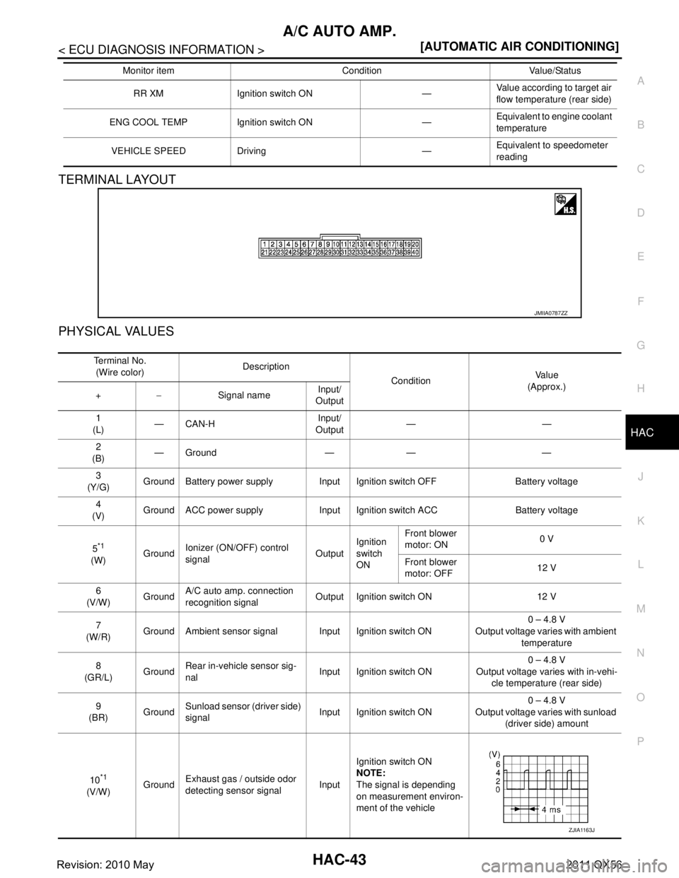
TERMINAL LAYOUT
PHYSICAL VALUES
RR XM Ignition switch ON — Value according to target air
flow temperature (rear side)
ENG COOL TEMP Ignition switch ON — Equivalent to engine coolant
temperature
VEHICLE SPEED Driving — Equivalent to speedometer
reading
Monitor item Condition Value/Status
JMIIA0787ZZ
Te r m i n a l N o .
(Wire color) Description
ConditionVa l u e
(Approx.)
+ − Signal name Input/
Output
1
(L) —CAN-H Input/
Output ——
2
(B) —Ground — — —
3
(Y/G) Ground Battery power supply Input Ignition switch OFF Battery voltage
4
(V) Ground ACC power supply Input Ignition switch ACC Battery voltage
5
*1
(W) Ground
Ionizer (ON/OFF) control
signal
OutputIgnition
switch
ON Front blower
motor: ON
0 V
Front blower
motor: OFF 12 V
6
(V/W) GroundA/C auto amp. connection
recognition signal Output Ignition switch ON 12 V
7
(W/R) Ground Ambient sensor signal Input Ignition switch ON 0 – 4.8 V
Output voltage varies with ambient temperature
8
(GR/L) Ground
Rear in-vehicle sensor sig-
nal Input Ignition switch ON 0 – 4.8 V
Output voltage varies with in-vehi-
cle temperature (rear side)
9
(BR) GroundSunload sensor (driver side)
signal
Input Ignition switch ON 0 – 4.8 V
Output voltage varies with sunload (driver side) amount
10
*1
(V/W) Ground
Exhaust gas / outside odor
detecting sensor signal InputIgnition switch ON
NOTE:
The signal is depending
on measurement environ-
ment of the vehicle
ZJIA1163J
Revision: 2010 May2011 QX56