2011 INFINITI QX56 air condition
[x] Cancel search: air conditionPage 3732 of 5598

SQUEAK AND RATTLE TROUBLE DIAGNOSESMIR-27
< SYMPTOM DIAGNOSIS >
C
DE
F
G H
I
J
K
M A
B
MIR
N
O P
Most of these incidents can be repaired by adjusting, securing or insulatingthe item(s) or component(s) caus-
ing the noise.
SUNROOF/HEADLINING
Noises in the sunroof/headlining area can often be traced to one of the following:
1. Sunroof lid, rail, linkage or seals making a rattle or light knockingnoise
2. Sunvisor shaft shaking in the holder
3. Front or rear windshield touching headlining and squeaking
Again, pressing on the components to stop the noise whil e duplicatingthe conditions can isolate most of these
incidents. Repairs usually consistof insulating with felt cloth tape.
SEATS
When isolating seat noise it's important to note the pos ition the seatis in and the load placed on the seat when
the noise is present. These conditionsshould be duplic ated when verifying and isolating the cause of the
noise.
Cause of seat noise include:
1. Headrest rods and holder
2. A squeak between the seat pad cushion and frame
3. The rear seatback lock and bracket
These noises can be isolated by moving or pressing on the suspectedcomponents while duplicating the condi-
tions under which the noise occurs. Most of these incidents can be repaired by repositioning the component
orapplying urethane tape to the contact area.
UNDERHOOD
Some interior noise may be caused by components under the hood or onthe engine wall. The noise is then
transmitted into the passenger compartment.
Causes of transmitted underhood noise include:
1. Any component mounted to the engine wall
2. Components that pass through the engine wall
3. Engine wall mounts and connectors
4. Loose radiator mounting pins
5. Hood bumpers out of adjustment
6. Hood striker out of adjustment
These noises can be difficult to isolate since they cannot be reached from the interior of the vehicle. The best
method is to secure, move or insulate one component at a time and test drive the vehicle. Also, engine RPM
or load can be changed to isolate the noise. Repairs c an usually be made by moving, adjusting, securing, or
insulating the component causing the noise.
Revision: 2010 May2011 QX56
Page 3749 of 5598

MWI-6
< SYSTEM DESCRIPTION >
COMPONENT PARTS
SYSTEM DESCRIPTION
COMPONENT PARTS
METER SYSTEM
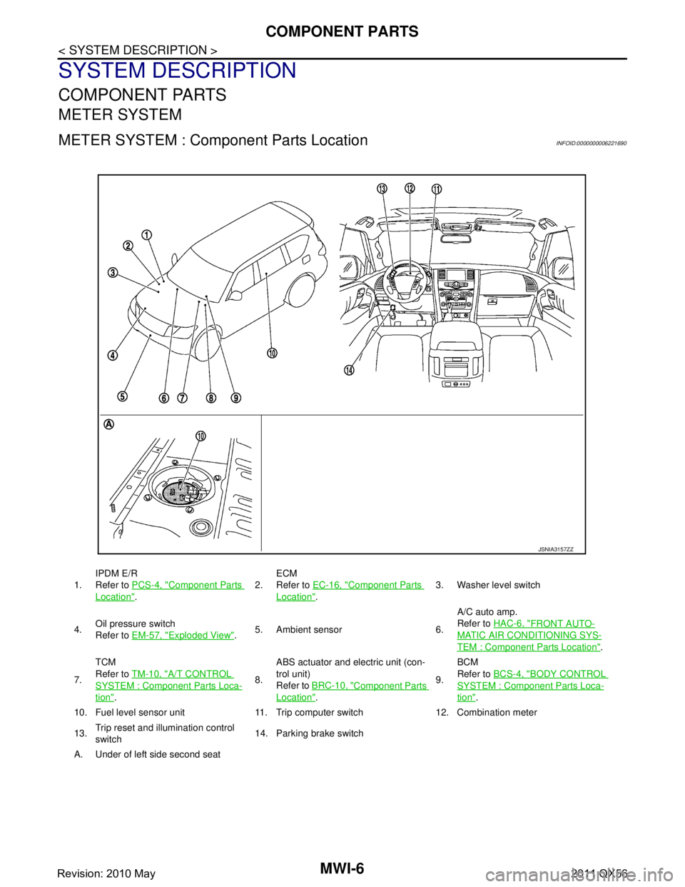
METER SYSTEM : Component Parts LocationINFOID:0000000006221690
1.IPDM E/R
Refer to
PCS-4, "Component Parts
Location". 2.
ECM
Refer to
EC-16, "
Component Parts
Location". 3. Washer level switch
4. Oil pressure switch
Refer to
EM-57, "
Exploded View".5. Ambient sensor 6. A/C auto amp.
Refer to
HAC-6, "
FRONT AUTO-
MATIC AIR CONDITIONING SYS-
TEM : Component Parts Location".
7. TCM
Refer to
TM-10, "
A/T CONTROL
SYSTEM : Componen t Parts Loca-
tion". 8.ABS actuator and electric unit (con-
trol unit)
Refer to
BRC-10, "
Component Parts
Location". 9.BCM
Refer to
BCS-4, "
BODY CONTROL
SYSTEM : Component Parts Loca-
tion".
10. Fuel level sensor unit 11. Trip computer switch 12. Combination meter
13. Trip reset and illumination control
switch 14. Parking brake switch
A. Under of left side second seat
JSNIA3157ZZ
Revision: 2010 May2011 QX56
Page 3765 of 5598

MWI-22
< SYSTEM DESCRIPTION >
SYSTEM
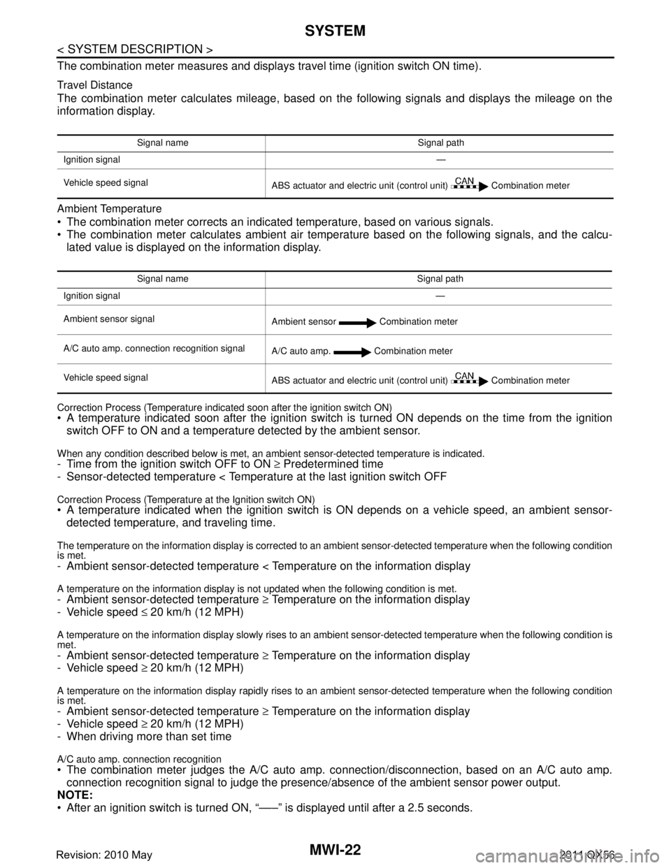
The combination meter measures and displays travel time (ignition switch ON time).
Travel Distance
The combination meter calculates mileage, based on the following signals and displays the mileage on the
information display.
Ambient Temperature
The combination meter corrects an indicated temperature, based on various signals.
The combination meter calculates ambient air temperature based on the following signals, and the calcu-
lated value is displayed on the information display.
Correction Process (Temperature indicated soon after the ignition switch ON) A temperature indicated soon after the ignition switch is turned ON depends on the time from the ignition switch OFF to ON and a temperatur e detected by the ambient sensor.
When any condition described below is met, an ambient sensor-detected temperature is indicated.- Time from the ignition switch OFF to ON ≥ Predetermined time
- Sensor-detected temperature < Temperat ure at the last ignition switch OFF
Correction Process (Temperature at the Ignition switch ON) A temperature indicated when the ignition switch is ON depends on a vehicle speed, an ambient sensor-
detected temperature, and traveling time.
The temperature on the information display is corrected to an am bient sensor-detected temperature when the following condition
is met.
- Ambient sensor-detected temperature < Temperature on the information display
A temperature on the information display is no t updated when the following condition is met.
- Ambient sensor-detected temperature ≥ Temperature on the information display
- Vehicle speed ≤ 20 km/h (12 MPH)
A temperature on the information display slowly rises to an ambient sensor-detected temperature when the following condition is
met.
- Ambient sensor-detected temperature ≥ Temperature on the information display
- Vehicle speed ≥ 20 km/h (12 MPH)
A temperature on the information display rapidly rises to an ambient sensor-detected temperature when the following condition
is met.
- Ambient sensor-detected temperature ≥ Temperature on the information display
- Vehicle speed ≥ 20 km/h (12 MPH)
- When driving more than set time
A/C auto amp. connection recognition
The combination meter judges the A/C auto amp. connection/disconnection, based on an A/C auto amp.
connection recognition signal to judge the presence/ absence of the ambient sensor power output.
NOTE:
After an ignition switch is turned ON, “–––” is displayed until after a 2.5 seconds.
Signal name Signal path
Ignition signal —
Vehicle speed signal ABS actuator and electric unit (control unit) Combination meter
Signal name Signal path
Ignition signal —
Ambient sensor signal Ambient sensor Combination meter
A/C auto amp. connection recognition signal A/C auto amp. Combination meter
Vehicle speed signal ABS actuator and electric unit (control unit) Combination meter
Revision: 2010 May2011 QX56
Page 3779 of 5598

MWI-36
< ECU DIAGNOSIS INFORMATION >
COMBINATION METER
LIGHT INDIgnition switch
ONTail lamp indicator lamp ON On
Tail lamp indicator lamp OFF Off
OIL W/L Ignition switch
ONOil pressure warning lamp ON On
Oil pressure warning lamp OFF Off
MIL Ignition switch
ONMalfunction indicator lamp ON On
Malfunction indicator lamp OFF Off
GLOW IND Ignition switch
ONNOTE:
This item is displayed, but cannot be moni-
tored.
Off
CRUISE IND Ignition switch
ONCRUISE indicator ON On
CRUISE indicator OFF Off
SET IND Ignition switch
ONSET indicator ON On
SET indicator OFF Off
CRUISE W/L Ignition switch
ONCRUISE warning lamp ON On
CRUISE warning lamp OFF Off
BA W/L Ignition switch
ONIBA OFF indicator lamp ON On
IBA OFF indicator lamp OFF Off
ATC/T-AMT W/L Ignition switch
ONA/T check warning lamp ON On
A/T check warning lamp OFF Off
ATF TEMP W/L Ignition switch
ONNOTE:
This item is displayed, but cannot be moni-
tored.
Off
4WD W/L Ignition switch
ON4WD warning lamp ON On
4WD warning lamp OFF Off
FUEL W/L Ignition switch
ONDuring low fuel warning indication On
Other than the above Off
WASHER W/L Ignition switch
ONDuring low washer flui
d warning indication On
Other than the above Off
AIR PRES W/L Ignition switch
ONLow tire pressure
warning lamp ON On
Low tire pressure warning lamp OFF Off
KEY G/Y W/L Ignition switch
ONKEY warning lamp (Green/Yellow) ON On
KEY warning lamp (Green/Yellow) OFF Off
KEY KNOB W/L Ignition switch
ONNOTE:
This item is displayed, but cannot be moni-
tored.
Off
AFS OFF IND Ignition switch
ONAFS OFF indicator lamp ON On
AFS OFF indicator lamp OFF Off
DDS W/L Ignition switch
ONNOTE:
This item is displayed, but cannot be moni-
tored.
Off
LANE W/L
Ignition switch
ONLane departure warning lamp ON On
Lane departure warning lamp OFF Off
LDP IND Ignition switch
ONLDP ON indicator lamp ON On
LDP ON indicator lamp OFF Off
AT P W / L Ignition switch
ONATP warning lamp ON On
ATP warning lamp OFF Off
Monitor Item Condition Value/Status
Revision: 2010 May2011 QX56
Page 3783 of 5598

MWI-40
< ECU DIAGNOSIS INFORMATION >
COMBINATION METER
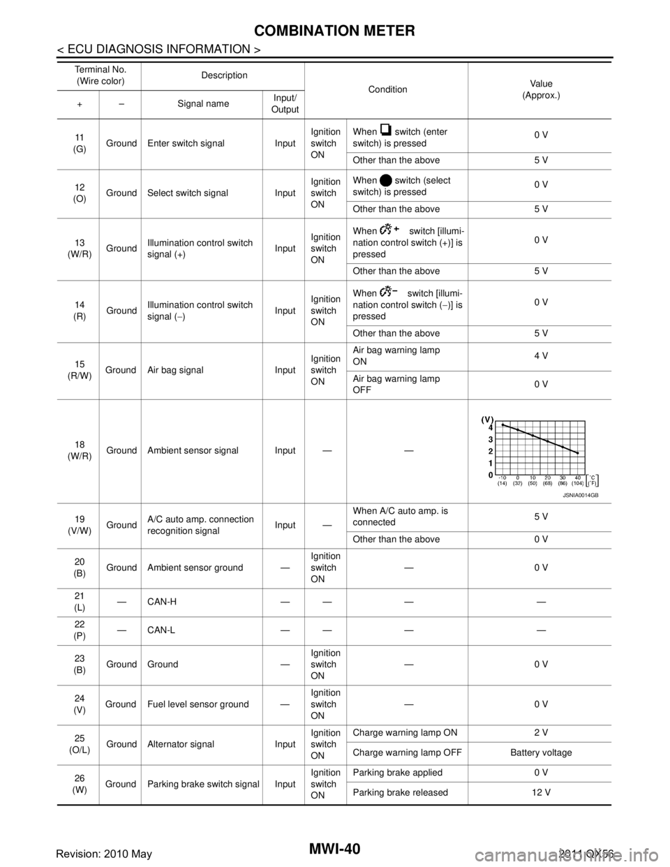
11
(G) Ground Enter switch signal Input Ignition
switch
ONWhen switch (enter
switch) is pressed
0 V
Other than the above 5 V
12
(O) Ground Select switch signal Input Ignition
switch
ONWhen switch (select
switch) is pressed
0 V
Other than the above 5 V
13
(W/R) Ground
Illumination control switch
signal (+) InputIgnition
switch
ON When switch [illumi-
nation control sw
itch (+)] is
pressed 0 V
Other than the above 5 V
14
(R) Ground Illumination control switch
signal (
−) InputIgnition
switch
ON When switch [illumi-
nation control switch (
−)] is
pressed 0 V
Other than the above 5 V
15
(R/W) Ground Air bag signal Input Ignition
switch
ONAir bag warning lamp
ON
4 V
Air bag warning lamp
OFF 0 V
18
(W/R) Ground Ambient sensor signal Input — —
19
(V/W) Ground A/C auto amp. connection
recognition signal Input —When A/C auto amp. is
connected
5 V
Other than the above 0 V
20
(B) Ground Ambient sensor ground — Ignition
switch
ON—0 V
21
(L) —CAN-H — — — —
22
(P) —CAN-L — — — —
23
(B) Ground Ground — Ignition
switch
ON
—0 V
24
(V) Ground Fuel level sensor ground — Ignition
switch
ON—0 V
25
(O/L) Ground Alternator signal Input Ignition
switch
ONCharge warning lamp ON 2 V
Charge warning lamp OFF Battery voltage
26
(W) Ground Parking brake switch signal Input Ignition
switch
ONParking brake applied 0 V
Parking brake released 12 V
Te r m i n a l N o .
(Wire color) Description
ConditionVa l u e
(Approx.)
+ – Signal name Input/
Output
JSNIA0014GB
Revision: 2010 May2011 QX56
Page 3800 of 5598

MWI
DIAGNOSIS AND REPAIR WORKFLOW (METER SYSTEM)MWI-57
< BASIC INSPECTION >
C
DE
F
G H
I
J
K L
M B A
O P
BASIC INSPECTION
DIAGNOSIS AND REPAIR WO RKFLOW (METER SYSTEM)
Work flowINFOID:0000000006221727
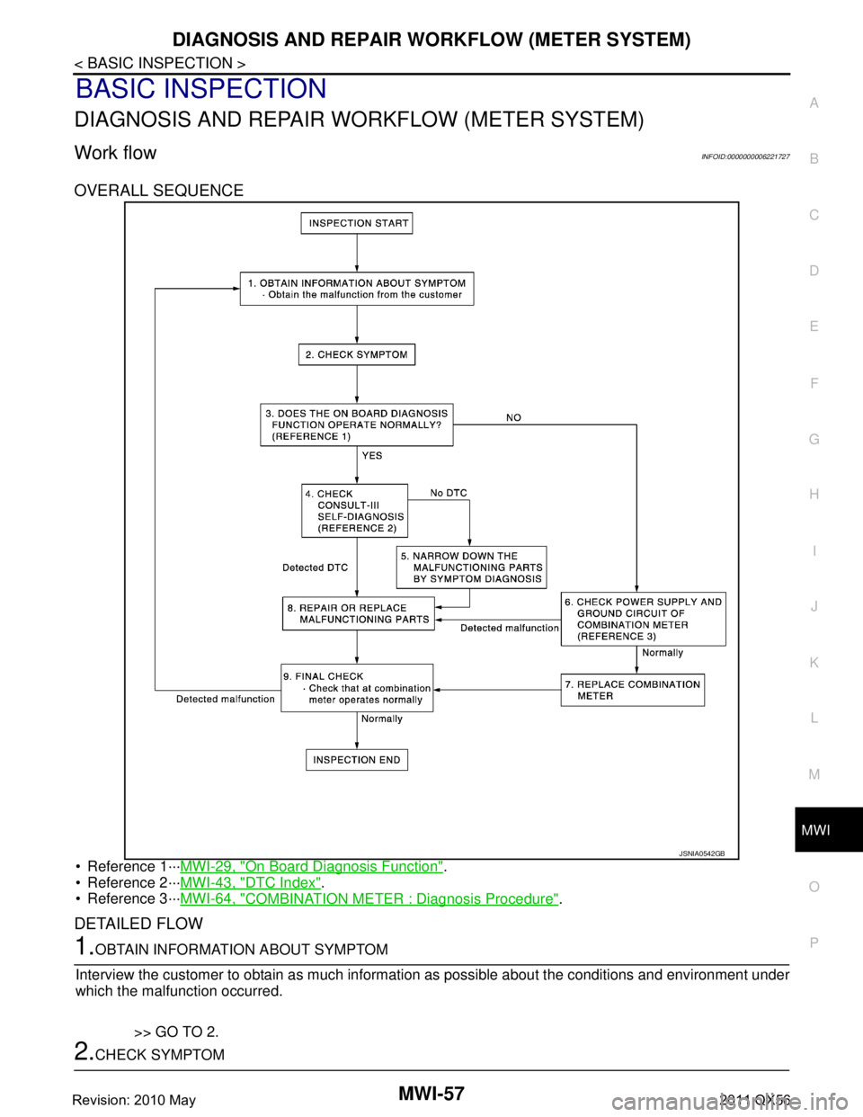
OVERALL SEQUENCE
Reference 1···MWI-29, "On Board Diagnosis Function".
Reference 2··· MWI-43, "
DTC Index".
Reference 3··· MWI-64, "
COMBINATION METER : Diagnosis Procedure".
DETAILED FLOW
1.OBTAIN INFORMATION ABOUT SYMPTOM
Interview the customer to obtain as much informa tion as possible about the conditions and environment under
which the malfunction occurred.
>> GO TO 2.
2.CHECK SYMPTOM
JSNIA0542GB
Revision: 2010 May2011 QX56
Page 3808 of 5598

MWI
TRIP RESET AND ILLUMINATION CONTROL SWITCH SIGNAL CIRCUIT
MWI-65
< DTC/CIRCUIT DIAGNOSIS >
C
D E
F
G H
I
J
K L
M B A
O P
TRIP RESET AND ILLUMINATION CO NTROL SWITCH SIGNAL CIRCUIT
Diagnosis ProcedureINFOID:0000000006221744
1.CHECK COMBINATION METER INPUT SIGNAL
1. Turn ignition switch ON.
2. Measure voltage between the following terminals of the combination meter.
Is the inspection result normal?
YES >> INSPECTION END
NO >> GO TO 2.
2.CHECK TRIP RESET AND ILLUMINATION CONTROL SWITCH SIGNAL CIRCUIT
1. Turn ignition switch OFF.
2. Disconnect combination meter connector and trip reset and illumination control switch connector.
3. Check continuity between combination meter harness connector and trip reset and illumination control switch harness connector.
4. Check continuity between combination meter harness connector and ground.
Is the inspection result normal?
YES >> GO TO 3.
NO >> Repair harness or connector.
3.CHECK TRIP RESET AND ILLUMINATI ON CONTROL SWITCH GROUND CIRCUIT
Check continuity between trip reset and i llumination control switch connector and ground.
(+) (−)
Condition Voltag e
(Approx.)
Combination meter
Ground
Connector Terminals
M34 8
When trip reset switch is pressed 0 V
Other than the above 5 V
13 When illumination control switch (+) is pressed 0 V
Other than the above 5 V
14 When illumination control switch (
−) is pressed 0 V
Other than the above 5 V
Te r m i n a l s Continuity
Combination meter Trip reset and illumination control switch
Connector Terminal Connector Terminal
M34 8
M83 5
Existed
13 3
14 4
Combination meter GroundContinuity
Connector Terminal
M34 8
Not existed
13
14
Trip reset and illumination control switch
GroundContinuity
Connector Terminal
M83 6 Existed
Revision: 2010 May2011 QX56
Page 3809 of 5598

MWI-66
< DTC/CIRCUIT DIAGNOSIS >
TRIP RESET AND ILLUMINATION CONTROL SWITCH SIGNAL CIRCUIT
Is the inspection result normal?
YES >> INSPECTION END
NO >> Repair harness or connector.
Component InspectionINFOID:0000000006221745
1.CHECK TRIP RESET AND ILLUMINATION CONTROL SWITCH
1. Turn ignition switch OFF.
2. Disconnect trip reset and illumination control switch connector.
3. Check trip reset and illumination control switch.
Is the inspection result normal?
YES >> INSPECTION END
NO >> Replace trip reset and illumination control switch. Refer to MWI-86, "
Removal and Installation".
Te r m i n a l s
Condition Continuity
Trip reset and illumina-
tion control switch
5
6When trip reset switch is pressed Existed
Other than the above Not existed
3 When illumination control switch (+) is pressed Existed
Other than the above Not existed
4 When illumination control switch (
−) is pressed Existed
Other than the above Not existed
Revision: 2010 May2011 QX56