2011 INFINITI QX56 air condition
[x] Cancel search: air conditionPage 3260 of 5598
![INFINITI QX56 2011 Factory Service Manual
HAC-154
< REMOVAL AND INSTALLATION >[AUTOMATIC AIR CONDITIONING]
DOOR MOTOR
3. Disconnect intake door motor connector.
INSTALLATION
Install in the reverse order of removal.
UPPER VENTILATOR DOOR MOT INFINITI QX56 2011 Factory Service Manual
HAC-154
< REMOVAL AND INSTALLATION >[AUTOMATIC AIR CONDITIONING]
DOOR MOTOR
3. Disconnect intake door motor connector.
INSTALLATION
Install in the reverse order of removal.
UPPER VENTILATOR DOOR MOT](/manual-img/42/57033/w960_57033-3259.png)
HAC-154
< REMOVAL AND INSTALLATION >[AUTOMATIC AIR CONDITIONING]
DOOR MOTOR
3. Disconnect intake door motor connector.
INSTALLATION
Install in the reverse order of removal.
UPPER VENTILATOR DOOR MOTOR
UPPER VENTILATOR DOOR MOTO
R : Removal and InstallationINFOID:0000000006276012
REMOVAL
1. Remove automatic drive position control unit. Refer to ADP-136, "Removal and Installation".
2. Remove fixing screws (A), and then remove intake door motor (1).
3. Disconnect intake door motor connector.
INSTALLATION
Install in the reverse order of removal.
REAR MODE DOOR MOTOR
REAR MODE DOOR MOTOR : Removal and InstallationINFOID:0000000006276013
REMOVAL
1. Remove luggage side lower finisher RH. Refer to INT-36, "LUGGAGE SIDE LOWER FINISHER :
Removal and Installation".
2. Remove fixing screws, and then remove rear mode door motor.
INSTALLATION
Install in the reverse order of removal.
REAR AIR MIX DOOR MOTOR
REAR AIR MIX DOOR MOTOR : Removal and InstallationINFOID:0000000006276014
REMOVAL
1. Remove rear A/C unit assembly. Refer to HA-47, "REAR A/C UNIT ASSEMBLY : Removal and Installa-
tion".
2. Remove fixing screws, and then remove air mix door motor.
INSTALLATION
Install in the reverse order of removal.
JMIIA0789ZZ
Revision: 2010 May2011 QX56
Page 3261 of 5598
![INFINITI QX56 2011 Factory Service Manual
IONIZER
HAC-155
< REMOVAL AND INSTALLATION > [AUTOMATIC AIR CONDITIONING]
C
D
E
F
G H
J
K L
M A
B
HAC
N
O P
IONIZER
Exploded ViewINFOID:0000000006276015
Refer to HA-41, "Exploded View".
Removal and INFINITI QX56 2011 Factory Service Manual
IONIZER
HAC-155
< REMOVAL AND INSTALLATION > [AUTOMATIC AIR CONDITIONING]
C
D
E
F
G H
J
K L
M A
B
HAC
N
O P
IONIZER
Exploded ViewINFOID:0000000006276015
Refer to HA-41, "Exploded View".
Removal and](/manual-img/42/57033/w960_57033-3260.png)
IONIZER
HAC-155
< REMOVAL AND INSTALLATION > [AUTOMATIC AIR CONDITIONING]
C
D
E
F
G H
J
K L
M A
B
HAC
N
O P
IONIZER
Exploded ViewINFOID:0000000006276015
Refer to HA-41, "Exploded View".
Removal and InstallationINFOID:0000000006276016
Removal
1. Remove instrument lower panel LH. Refer to IP-14, "Removal and Installation".
2. Remove mounting screws, and then remove ionizer from A/C unit assembly. CAUTION:
Never tough the surface (ceramic part) of th e ionizer. It is the discharge electrode.
3. Disconnect ionizer harness connector.
INSTALLATION
Note the following item, install in the reverse order of removal.
CAUTION:
If there is dirt, use a clean clot h and clean the discharge electrode (ceramic part) of the ionizer.
Revision: 2010 May2011 QX56
Page 3279 of 5598

INL-12
< SYSTEM DESCRIPTION >
DIAGNOSIS SYSTEM (BCM)
DIAGNOSIS SYSTEM (BCM)
COMMON ITEM
COMMON ITEM : CONSULT-III Function (BCM - COMMON ITEM)INFOID:0000000006368143
APPLICATION ITEM
CONSULT-III performs the following functions via CAN communication with BCM.
SYSTEM APPLICATION
BCM can perform the following functions for each system.
NOTE:
It can perform the diagnosis modes except the following for all sub system selection items.
×: Applicable item
*: This item is indicated, but not used.
FREEZE FRAME DATA (FFD)
The BCM records the following vehicle condition at the time a particular DTC is detected, and displays on
CONSULT-III.
Diagnosis mode Function Description
Work Support Changes the setting for each system function.
Self Diagnostic Result Displays the diagnosis results judged by BCM. Refer to BCS-57, "
DTCIndex".
CAN Diag Support Monitor Monitors the reception status of CAN communication viewed from BCM. Refer to CONSULT-III opera-
tion manual.
Data Monitor The BCM input/output signals are displayed.
Active Test The signals used to activate ea ch device are forcibly supplied from BCM.
Ecu Identification The BCM part number is displayed.
Configuration Read and save the vehicle specification.
Write the vehicle specification when replacing BCM.
System Sub system selection item Diagnosis mode
Work Support Data Monitor Active Test
Door lock DOOR LOCK ×××
Rear window defogger REAR DEFOGGER ××
Warning chime BUZZER ××
Interior room lamp timer INT LAMP ×××
Exterior lamp HEAD LAMP ×××
Wiper and washer WIPER ×××
Turn signal and hazard warning lamps FLASHER ×××
— AIR CONDITONER* ××
Intelligent Key system
Engine start system INTELLIGENT KEY
×××
Combination switch COMB SW ×
Body control system BCM ×
IVIS IMMU ×××
Interior room lamp battery saver BATTERY SAVER ×××
Back door TRUNK ×
Vehicle security system THEFT ALM ×××
RAP system RETAINED PWR ×
Signal buffer system SIGNAL BUFFER ××
Revision: 2010 May2011 QX56
Page 3327 of 5598

INL-60
< DTC/CIRCUIT DIAGNOSIS >
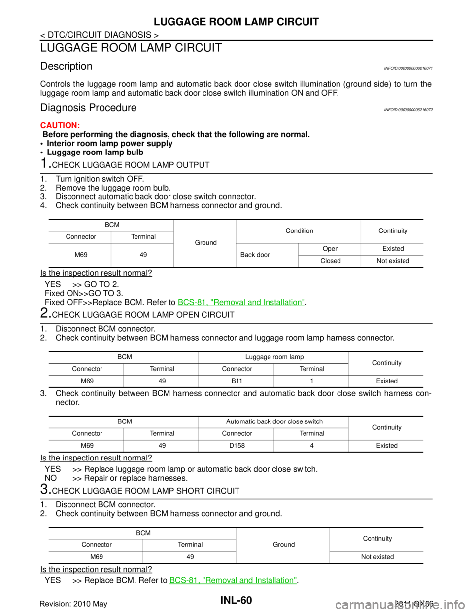
LUGGAGE ROOM LAMP CIRCUIT
LUGGAGE ROOM LAMP CIRCUIT
DescriptionINFOID:0000000006216071
Controls the luggage room lamp and automatic back door close switch illumination (ground side) to turn the
luggage room lamp and automatic back door close switch illumination ON and OFF.
Diagnosis ProcedureINFOID:0000000006216072
CAUTION:
Before performing the diagnosis, check that the following are normal.
Interior room lamp power supply
Luggage room lamp bulb
1.CHECK LUGGAGE ROOM LAMP OUTPUT
1. Turn ignition switch OFF.
2. Remove the luggage room bulb.
3. Disconnect automatic back door close switch connector.
4. Check continuity between BCM harness connector and ground.
Is the inspection result normal?
YES >> GO TO 2.
Fixed ON>>GO TO 3.
Fixed OFF>>Replace BCM. Refer to BCS-81, "
Removal and Installation".
2.CHECK LUGGAGE ROOM LAMP OPEN CIRCUIT
1. Disconnect BCM connector.
2. Check continuity between BCM harness c onnector and luggage room lamp harness connector.
3. Check continuity between BCM harness connector and automatic back door close switch harness con-
nector.
Is the inspection result normal?
YES >> Replace luggage room lamp or automatic back door close switch.
NO >> Repair or replace harnesses.
3.CHECK LUGGAGE ROOM LAMP SHORT CIRCUIT
1. Disconnect BCM connector.
2. Check continuity between BCM harness connector and ground.
Is the inspection result normal?
YES >> Replace BCM. Refer to BCS-81, "Removal and Installation".
BCM
Ground Condition Continuity
Connector Terminal
M69 49 Back door Open Existed
Closed Not existed
BCM Luggage room lamp Continuity
Connector Terminal Connector Terminal
M69 49 B11 1 Existed
BCM Automatic back door close switch Continuity
Connector Terminal Connector Terminal
M69 49 D158 4 Existed
BCM GroundContinuity
Connector Terminal
M69 49 Not existed
Revision: 2010 May2011 QX56
Page 3331 of 5598

INL-64
< DTC/CIRCUIT DIAGNOSIS >
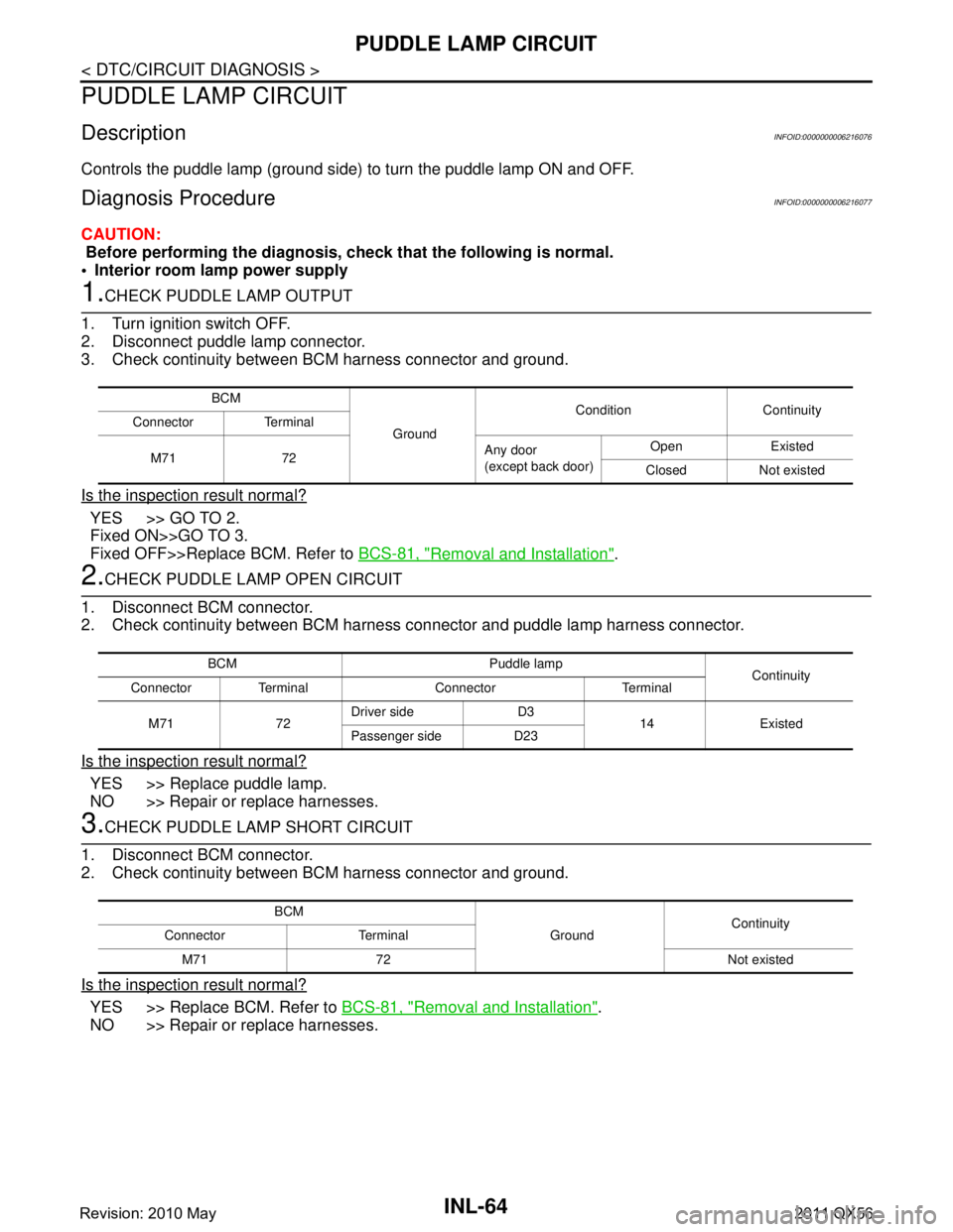
PUDDLE LAMP CIRCUIT
PUDDLE LAMP CIRCUIT
DescriptionINFOID:0000000006216076
Controls the puddle lamp (ground side) to turn the puddle lamp ON and OFF.
Diagnosis ProcedureINFOID:0000000006216077
CAUTION:
Before performing the diagnosis, check that the following is normal.
Interior room lamp power supply
1.CHECK PUDDLE LAMP OUTPUT
1. Turn ignition switch OFF.
2. Disconnect puddle lamp connector.
3. Check continuity between BCM harness connector and ground.
Is the inspection result normal?
YES >> GO TO 2.
Fixed ON>>GO TO 3.
Fixed OFF>>Replace BCM. Refer to BCS-81, "
Removal and Installation".
2.CHECK PUDDLE LAMP OPEN CIRCUIT
1. Disconnect BCM connector.
2. Check continuity between BCM harness connector and puddle lamp harness connector.
Is the inspection result normal?
YES >> Replace puddle lamp.
NO >> Repair or replace harnesses.
3.CHECK PUDDLE LAMP SHORT CIRCUIT
1. Disconnect BCM connector.
2. Check continuity between BCM harness connector and ground.
Is the inspection result normal?
YES >> Replace BCM. Refer to BCS-81, "Removal and Installation".
NO >> Repair or replace harnesses.
BCM
Ground Condition Continuity
Connector Terminal
M71 72 Any door
(except back door)Open Existed
Closed Not existed
BCM Puddle lamp Continuity
Connector Terminal Connector Terminal
M71 72 Driver side D3
14 Existed
Passenger side D23
BCM
GroundContinuity
Connector Terminal
M71 72 Not existed
Revision: 2010 May2011 QX56
Page 3332 of 5598

PUSH-BUTTON IGNITION SWITCH ILLUMINATION CIRCUIT
INL-65
< DTC/CIRCUIT DIAGNOSIS >
C
D E
F
G H
I
J
K
M A
B
INL
N
O P
PUSH-BUTTON IGNITION SWIT CH ILLUMINATION CIRCUIT
Component Function CheckINFOID:0000000006265016
1.CHECK PUSH-BUTTON IGNITION SWITCH ILLUMINATION OPERATION
CONSULT-III ACTIVE TEST
1. Turn the ignition switch ON.
2. Select “ENGINE SW ILLUMI” of BCM (I NTELLIGENT KEY) active test item.
3. With operating the test items, check that the pus h-button ignition switch illumination turns ON/OFF.
Does the push-button ignition switch illumination turn ON/OFF?
YES >> Push-button ignition switch illumination circuit is normal.
NO >> Refer to INL-65, "
Diagnosis Procedure".
Diagnosis ProcedureINFOID:0000000006265017
1.CHECK PUSH-BUTTON IGNITION SWITCH ILLUMINATION POWER SUPPLY OUTPUT
1. Turn ignition switch OFF.
2. Lighting switch OFF.
3. Disconnect push-button ignition switch connector.
4. Check voltage between push-button ignition switch harness connector and ground.
Is the inspection result normal?
YES >> GO TO 4.
NO >> GO TO 2.
2.CHECK PUSH-BUTTON IGNITION SWITCH ILLU MINATION POWER SUPPLY OPEN CIRCUIT
1. Turn the ignition switch OFF.
2. Disconnect BCM connector.
3. Check continuity between BCM harness connector and the push-button ignition switch harness connector.
Is the inspection result normal?
YES >> GO TO 3.
NO >> Repair or replace harnesses.
3.CHECK PUSH-BUTTON IGNITION SWITCH ILLU MINATION POWER SUPPLY SHORT CIRCUIT
Check continuity between BCM harness connector and ground.
Is the inspection result normal?
YES >> Replace BCM. Refer to BCS-81, "Removal and Installation".
On : Push-button ignition
switch illumination ON
Off : Push-button ignition switch illumination OFF
(+)
(–) Condition Vo l ta g e
(Approx.)
Push-button ignition switch
Connector Terminal
M101 3 Ground Push-button ignition
switch illuminationON Condition 12 V
OFF Condition 0 V
BCM Push-button ignition switch Continuity
Connector Terminal Connector Terminal
M71 90 M101 3 Existed
BCM GroundContinuity
Connector Terminal
M71 90 Not existed
Revision: 2010 May2011 QX56
Page 3333 of 5598

INL-66
< DTC/CIRCUIT DIAGNOSIS >
PUSH-BUTTON IGNITION SWITCH ILLUMINATION CIRCUIT
NO >> Repair or replace harnesses.
4.CHECK PUSH-BUTTON IGNITION SWITCH ILLUMINATION GROUND CIRCUIT-1
1. Connect push-button ignition switch connector.
2. Check voltage between BCM harness connector and ground.
Is the inspection result normal?
YES >> GO TO 5.
NO >> Replace BCM. Refer to BCS-81, "
Removal and Installation".
5.CHECK PUSH-BUTTON IGNITION SWIT CH ILLUMINATION GROUND CIRCUIT-2
1. Check continuity between push-button ignition switch harness connector and BCM harness connector.
2. Check continuity between push-button ignition switch harness connector and ground.
Is the inspection result normal?
YES >> Replace push-button ignition switch.
NO >> Repair or replace harnesses.
(+) (–) Condition Vo l ta g e
(Approx.)
BCM
Connector Terminal
M71 92 Ground Push-button ignition switch
illuminationON Condition 0 V
Push-button ignition switch BCM
Continuity
Connector Terminal Connector Terminal
M101 2 M71 92 Existed
Push-button ignition switch GroundContinuity
Connector Terminal
M101 2 Not existed
Revision: 2010 May2011 QX56
Page 3356 of 5598

SQUEAK AND RATTLE TROUBLE DIAGNOSESINT-7
< SYMPTOM DIAGNOSIS >
C
DE
F
G H
I
K L
M A
B
INT
N
O P
SYMPTOM DIAGNOSIS
SQUEAK AND RATTLE TROUBLE DIAGNOSES
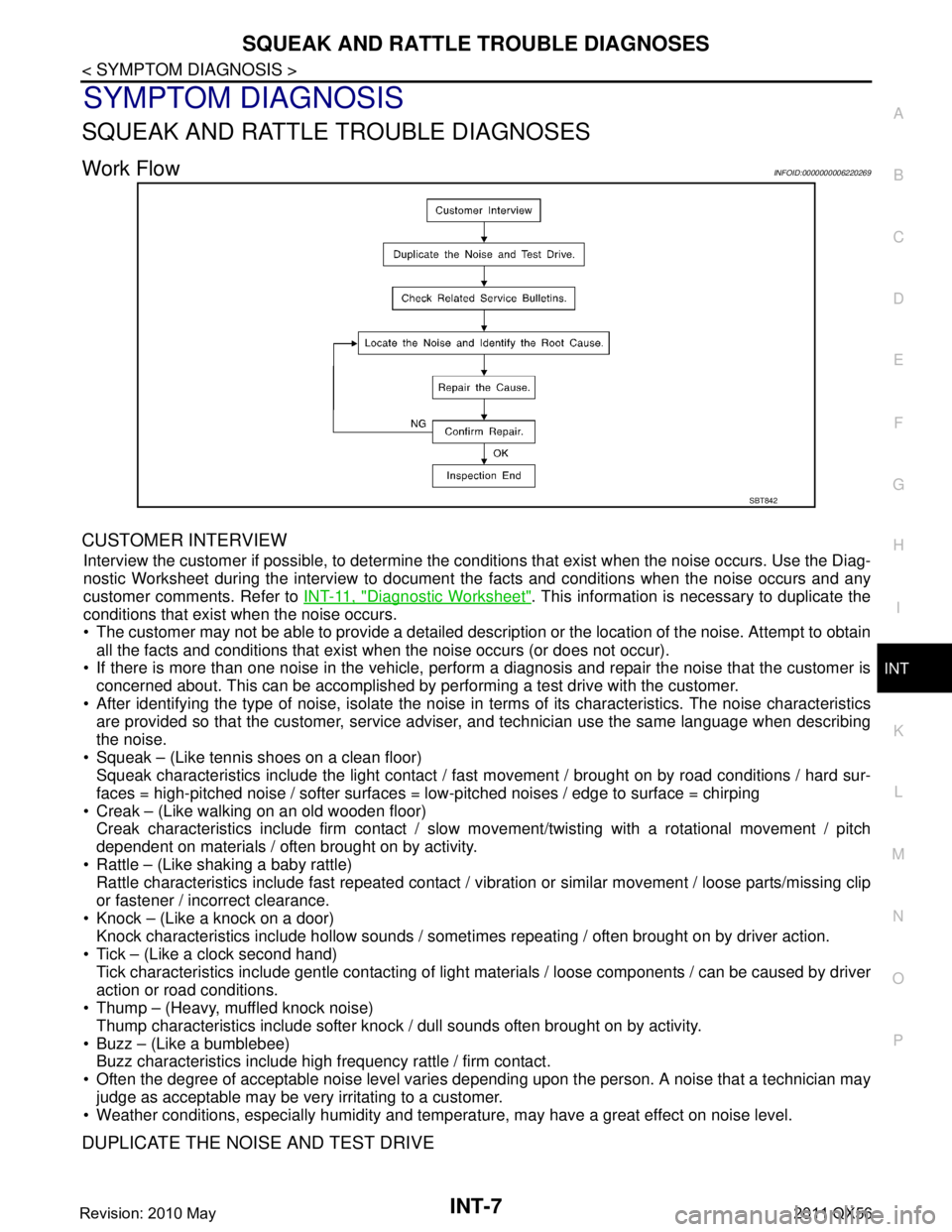
Work FlowINFOID:0000000006220269
CUSTOMER INTERVIEW
Interview the customer if possible, to determine the conditions that exist when the noise occurs. Use the Diag-
nostic Worksheet during the interv iew to document the facts and conditions when the noise occurs and any
customer comments. Refer to INT-11, "
Diagnostic Worksheet". This information is necessary to duplicate the
conditions that exist when the noise occurs.
The customer may not be able to provide a detailed description or the location of the noise. Attempt to obtain
all the facts and conditions that exist when the noise occurs (or does not occur).
If there is more than one noise in the vehicle, perform a diagnosis and repair the noise that the customer is
concerned about. This can be accomplished by performing a test drive with the customer.
After identifying the type of noise, isolate the noise in terms of its characteristics. The noise characteristics
are provided so that the customer, service advis er, and technician use the same language when describing
the noise.
Squeak – (Like tennis shoes on a clean floor) Squeak characteristics include the light contact / fast movement / brought on by road conditions / hard sur-
faces = high-pitched noise / softer surfaces = low-pitched noises / edge to surface = chirping
Creak – (Like walking on an old wooden floor) Creak characteristics include firm contact / slow mo vement/twisting with a rotational movement / pitch
dependent on materials / often brought on by activity.
Rattle – (Like shaking a baby rattle) Rattle characteristics include fast repeated contact / vi bration or similar movement / loose parts/missing clip
or fastener / incorrect clearance.
Knock – (Like a knock on a door) Knock characteristics include hollow sounds / someti mes repeating / often brought on by driver action.
Tick – (Like a clock second hand) Tick characteristics include gentle contacting of light materials / loose components / can be caused by driver
action or road conditions.
Thump – (Heavy, muffled knock noise)
Thump characteristics include softer knock / dull sounds often brought on by activity.
Buzz – (Like a bumblebee) Buzz characteristics include high frequency rattle / firm contact.
Often the degree of acceptable noise level varies depending upon the person. A noise that a technician may
judge as acceptable may be very irritating to a customer.
Weather conditions, especially humidity and temperat ure, may have a great effect on noise level.
DUPLICATE THE NOISE AND TEST DRIVE
SBT842
Revision: 2010 May2011 QX56