2011 INFINITI QX56 air condition
[x] Cancel search: air conditionPage 4141 of 5598

PWC-56
< DTC/CIRCUIT DIAGNOSIS >
POWER WINDOW SERIAL LINK
NO >> GO TO 3.
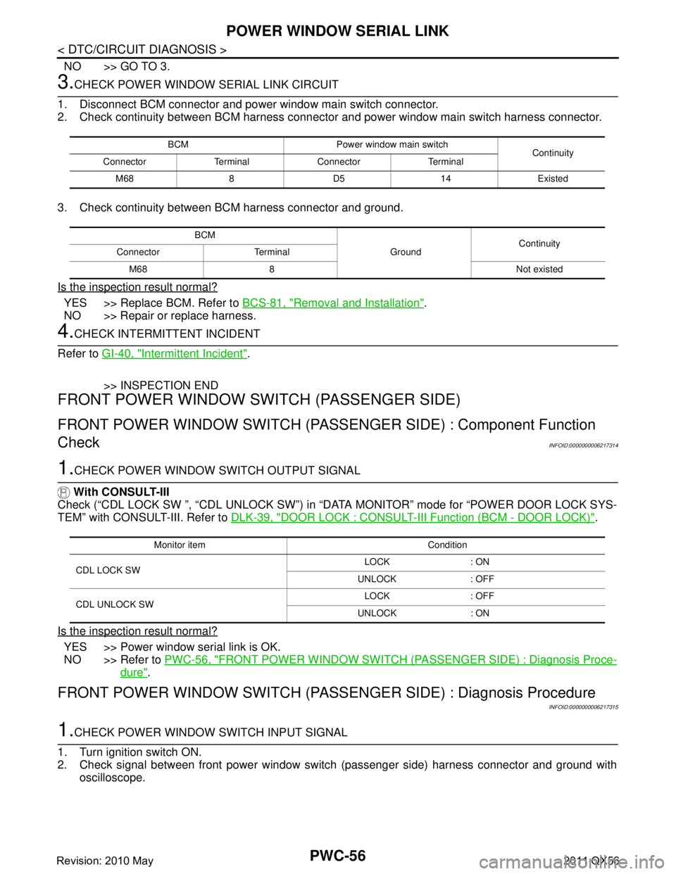
3.CHECK POWER WINDOW SERIAL LINK CIRCUIT
1. Disconnect BCM connector and power window main switch connector.
2. Check continuity between BCM harness connector and power window main switch harness connector.
3. Check continuity between BCM harness connector and ground.
Is the inspection result normal?
YES >> Replace BCM. Refer to BCS-81, "Removal and Installation".
NO >> Repair or replace harness.
4.CHECK INTERMITTENT INCIDENT
Refer to GI-40, "
Intermittent Incident".
>> INSPECTION END
FRONT POWER WINDOW SWITCH (PASSENGER SIDE)
FRONT POWER WINDOW SWITCH (PASSENGE R SIDE) : Component Function
Check
INFOID:0000000006217314
1.CHECK POWER WINDOW SWITCH OUTPUT SIGNAL
With CONSULT-III
Check (“CDL LOCK SW ”, “CDL UNLOCK SW”) in “D ATA MONITOR” mode for “POWER DOOR LOCK SYS-
TEM” with CONSULT-III. Refer to DLK-39, "
DOOR LOCK : CONSULT-III Function (BCM - DOOR LOCK)".
Is the inspection result normal?
YES >> Power window serial link is OK.
NO >> Refer to PWC-56, "
FRONT POWER WINDOW SWITCH (PAS SENGER SIDE) : Diagnosis Proce-
dure".
FRONT POWER WINDOW SWITCH (PASSENGE R SIDE) : Diagnosis Procedure
INFOID:0000000006217315
1.CHECK POWER WINDOW SWITCH INPUT SIGNAL
1. Turn ignition switch ON.
2. Check signal between front power window switch (passenger side) harness connector and ground with
oscilloscope.
BCM Power window main switch Continuity
Connector Terminal Connector Terminal
M68 8 D5 14 Existed
BCM GroundContinuity
Connector Terminal
M68 8 Not existed
Monitor item Condition
CDL LOCK SW LOCK : ON
UNLOCK : OFF
CDL UNLOCK SW LOCK : OFF
UNLOCK : ON
Revision: 2010 May2011 QX56
Page 4144 of 5598

POWER WINDOW SERIAL LINKPWC-59
< DTC/CIRCUIT DIAGNOSIS >
C
DE
F
G H
I
J
L
M A
B
PWC
N
O P
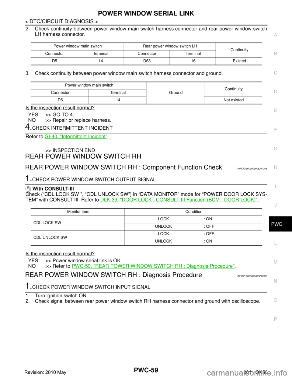
2. Check continuity between power window main s witch harness connector and rear power window switch
LH harness connector.
3. Check continuity between power window main switch harness connector and ground.
Is the inspection result normal?
YES >> GO TO 4.
NO >> Repair or replace harness.
4.CHECK INTERMITTENT INCIDENT
Refer to GI-40, "
Intermittent Incident".
>> INSPECTION END
REAR POWER WINDOW SWITCH RH
REAR POWER WINDOW SWITCH RH : Component Function CheckINFOID:0000000006217318
1.CHECK POWER WINDOW SWITCH OUTPUT SIGNAL
With CONSULT-III
Check (“CDL LOCK SW ”, “CDL UNLOCK SW”) in “D ATA MONITOR” mode for “POWER DOOR LOCK SYS-
TEM” with CONSULT-III. Refer to DLK-39, "
DOOR LOCK : CONSULT-III Function (BCM - DOOR LOCK)".
Is the inspection result normal?
YES >> Power window serial link is OK.
NO >> Refer to PWC-59, "
REAR POWER WINDOW SWITCH RH : Diagnosis Procedure".
REAR POWER WINDOW SWITCH RH : Diagnosis ProcedureINFOID:0000000006217319
1.CHECK POWER WINDOW SWITCH INPUT SIGNAL
1. Turn ignition switch ON.
2. Check signal between rear power window swit ch RH harness connector and ground with oscilloscope.
Power window main switch Rear power window switch LH
Continuity
Connector Terminal Connector Terminal
D5 14 D63 16 Existed
Power window main switch GroundContinuity
Connector Terminal
D5 14 Not existed
Monitor item Condition
CDL LOCK SW LOCK : ON
UNLOCK : OFF
CDL UNLOCK SW LOCK : OFF
UNLOCK : ON
Revision: 2010 May2011 QX56
Page 4182 of 5598
![INFINITI QX56 2011 Factory Service Manual
PWO
POWER SUPPLY AND GROUND CIRCUITPWO-23
< DTC/CIRCUIT DIAGNOSIS > [AC 120 V OUTLET]
C
D
E
F
G H
I
J
K L
B A
O P
N
DTC/CIRCUIT DIAGNOSIS
POWER SUPPLY AND GROUND CIRCUIT
Diagnosis ProcedureINFOID:000 INFINITI QX56 2011 Factory Service Manual
PWO
POWER SUPPLY AND GROUND CIRCUITPWO-23
< DTC/CIRCUIT DIAGNOSIS > [AC 120 V OUTLET]
C
D
E
F
G H
I
J
K L
B A
O P
N
DTC/CIRCUIT DIAGNOSIS
POWER SUPPLY AND GROUND CIRCUIT
Diagnosis ProcedureINFOID:000](/manual-img/42/57033/w960_57033-4181.png)
PWO
POWER SUPPLY AND GROUND CIRCUITPWO-23
< DTC/CIRCUIT DIAGNOSIS > [AC 120 V OUTLET]
C
D
E
F
G H
I
J
K L
B A
O P
N
DTC/CIRCUIT DIAGNOSIS
POWER SUPPLY AND GROUND CIRCUIT
Diagnosis ProcedureINFOID:0000000006257089
1.CHECK FUSE
Check that the following fuse is not blown.
Is the fuse fusing?
YES >> Replace the blown fuse after repairing the affected circuit if a fuse is blown.
NO >> GO TO 2.
2.CHECK INVERTER UNIT POWER SUPPLY CIRCUIT
Check voltage between inverter unit harness connector and ground.
Is the inspection result normal?
YES >> GO TO 3.
NO >> Repair or replace the inverter unit power supply circuit.
3.CHECK INVERTER UNIT GROUND CIRCUIT
1. Turn the ignition switch OFF.
2. Disconnect the inverter unit connector.
3. Check for continuity between inverter unit harness connector and ground.
Is the inspection result normal?
YES >> INSPECTION END
NO >> Repair or replace the inverter unit ground circuit.
Signal name Fuse No.
Battery power supply 79
Te r m i n a l Condition
Vo l ta g e
(Approx.)
(+) (–)
Inverter unit GroundIgnition switch
Connector Terminal
M143 4 OFF Battery voltage
Inverter unit GroundContinuity
Connector Terminal
M143 8 Existed
Revision: 2010 May2011 QX56
Page 4183 of 5598
![INFINITI QX56 2011 Factory Service Manual
PWO-24
< DTC/CIRCUIT DIAGNOSIS >[AC 120 V OUTLET]
AC 120 V OUTLET MAIN SWITCH POWER SUPPLY CIRCUIT
AC 120 V OUTLET MAIN SWITCH
POWER SUPPLY CIRCUIT
Diagnosis ProcedureINFOID:0000000006257095
1.CHECK INFINITI QX56 2011 Factory Service Manual
PWO-24
< DTC/CIRCUIT DIAGNOSIS >[AC 120 V OUTLET]
AC 120 V OUTLET MAIN SWITCH POWER SUPPLY CIRCUIT
AC 120 V OUTLET MAIN SWITCH
POWER SUPPLY CIRCUIT
Diagnosis ProcedureINFOID:0000000006257095
1.CHECK](/manual-img/42/57033/w960_57033-4182.png)
PWO-24
< DTC/CIRCUIT DIAGNOSIS >[AC 120 V OUTLET]
AC 120 V OUTLET MAIN SWITCH POWER SUPPLY CIRCUIT
AC 120 V OUTLET MAIN SWITCH
POWER SUPPLY CIRCUIT
Diagnosis ProcedureINFOID:0000000006257095
1.CHECK FUSE
Check that the following fuse is not blown.
Is the fuse fusing?
YES >> Replace the blown fuse after repairing the affected circuit if a fuse is blown.
NO >> GO TO 2.
2.CHECK POWER SUPPLY FOR AC 120 V OUTLET MAIN SWITCH
1. Turn ignition switch ON.
2. Check for voltage between the AC 120 V main switch harness connector and ground.
Is the inspection result normal?
YES >> INSPECTION END
NO >> Repair the AC 120 V main switch power supply circuit.
Signal name Fuse No.
Ignition power supply 3
Te r m i n a l s Condition
Vo l ta g e
(Approx.)
(+) (–)
AC 120 V outlet main switch
GroundIgnition switch
Connector Terminal
M144 1 OFF 0 V
ON 12 V
Revision: 2010 May2011 QX56
Page 4184 of 5598
![INFINITI QX56 2011 Factory Service Manual
PWO
AC 120 V OUTLET MAIN SWITCH INPUT SIGNAL CIRCUITPWO-25
< DTC/CIRCUIT DIAGNOSIS > [AC 120 V OUTLET]
C
D
E
F
G H
I
J
K L
B A
O P
N
AC 120 V OUTLET MAIN SWITCH
INPUT SIGNAL CIRCUIT
Diagnosis Proced INFINITI QX56 2011 Factory Service Manual
PWO
AC 120 V OUTLET MAIN SWITCH INPUT SIGNAL CIRCUITPWO-25
< DTC/CIRCUIT DIAGNOSIS > [AC 120 V OUTLET]
C
D
E
F
G H
I
J
K L
B A
O P
N
AC 120 V OUTLET MAIN SWITCH
INPUT SIGNAL CIRCUIT
Diagnosis Proced](/manual-img/42/57033/w960_57033-4183.png)
PWO
AC 120 V OUTLET MAIN SWITCH INPUT SIGNAL CIRCUITPWO-25
< DTC/CIRCUIT DIAGNOSIS > [AC 120 V OUTLET]
C
D
E
F
G H
I
J
K L
B A
O P
N
AC 120 V OUTLET MAIN SWITCH
INPUT SIGNAL CIRCUIT
Diagnosis ProcedureINFOID:0000000006257093
1.CHECK HARNESS BETWEEN INVERTER UNIT AND AC 120 V OUTLET MAIN SWITCH
1. Turn ignition switch OFF.
2. Disconnect inverter unit connector and AC 120 V outlet main switch connector.
3. Check for continuity between the inverter unit harness connector and AC 120 V outlet main switch har- ness connector.
4. Check for continuity between inverter unit harness connector and ground.
Is the inspection result normal?
YES >> GO TO 2.
NO >> Repair the harnesses or connectors.
2.CHECK AC 120 V OUTLET MAIN SWITCH INPUT SIGNAL
1. Connect inverter unit connector and AC 120 V outlet main switch connector.
2. Turn ignition switch ON.
3. AC 120 V outlet main switch ON.
4. Check for voltage between the inverter unit harness connector and ground.
Is the inspection result normal?
YES >> INSPECTION END
NO >> GO TO 3.
3.CHECK AC 120 V OUTLET MAIN SWITCH
1. Turn ignition switch OFF.
2. Remove AC 120 V outlet main switch.
3. Check AC 120 V outlet main switch. Refer to PWO-25, "
Component Inspection".
Is the inspection result normal?
YES >> INSPECTION END
NO >> Replace AC 120 V outlet main switch.
Component InspectionINFOID:0000000006257096
1.CHECK AC 120 V OUTLET MAIN SWITCH
Check continuity of AC 120 V outlet main switch.
Inverter unit AC 120 V outlet main switch Continuity
Connector Terminal Connector Terminal
M1436M1443Existed
Inverter unit GroundContinuity
Connector Terminal
M143 6 Not existed
Te r m i n a l s Condition
Vol tag e
(Approx.)
(+) (–)
Inverter unit
GroundAC 120 V out-
let main switch
Connector Terminal
M143 6 OFF 0 V
ON 12 V
Revision: 2010 May2011 QX56
Page 4186 of 5598
![INFINITI QX56 2011 Factory Service Manual
PWO
AC 120 V POWER OUTPUT CIRCUIT
PWO-27
< DTC/CIRCUIT DIAGNOSIS > [AC 120 V OUTLET]
C
D
E
F
G H
I
J
K L
B A
O P
N
AC 120 V POWER OUTPUT CIRCUIT
Diagnosis ProcedureINFOID:0000000006257091
1.CHECK HAR INFINITI QX56 2011 Factory Service Manual
PWO
AC 120 V POWER OUTPUT CIRCUIT
PWO-27
< DTC/CIRCUIT DIAGNOSIS > [AC 120 V OUTLET]
C
D
E
F
G H
I
J
K L
B A
O P
N
AC 120 V POWER OUTPUT CIRCUIT
Diagnosis ProcedureINFOID:0000000006257091
1.CHECK HAR](/manual-img/42/57033/w960_57033-4185.png)
PWO
AC 120 V POWER OUTPUT CIRCUIT
PWO-27
< DTC/CIRCUIT DIAGNOSIS > [AC 120 V OUTLET]
C
D
E
F
G H
I
J
K L
B A
O P
N
AC 120 V POWER OUTPUT CIRCUIT
Diagnosis ProcedureINFOID:0000000006257091
1.CHECK HARNESS BETWEEN INVERTER UNIT AND AC 120 V OUTLET
1. Turn ignition switch OFF.
2. Disconnect inverter unit connector and AC 120 V outlet connector.
3. Check for continuity between the inverter uni t harness connector and AC 120 V outlet harness connector.
4. Check for continuity between inverter unit harness connector and ground.
5. Check for continuity between inverter unit harness connector.
Is the inspection result normal?
YES >> GO TO 2.
NO >> Repair or replace the harnesses or connectors.
2.CHECK INVERTER UNIT OUTPUT SIGNAL
1. Connect inverter unit connector and AC 120 V outlet connector.
2. Turn ignition switch ON.
3. AC 120 V outlet main switch ON. (AC 120 V outlet main switch indicator ON)
4. Check voltage between inverter unit harness connector.
CAUTION:
To measure AC 120 V output signal, al ways use the circuit tester AC range.
Never allow the probes to contact each other.
Is the inspection result normal?
YES >> GO TO 3
NO >> Replace inverter unit.
3.CHECK AC 120 V OUTLET VOLTAGE
1. AC 120 V outlet main switch ON. (AC 120 V outlet main switch indicator ON)
2. Check voltage between AC 120 V outlet.
Inverter unit AC 120 V outlet Continuity
Connector Terminal Connector Terminal
M143 5
M145 1
Existed
12
Inverter unit GroundContinuity
Connector Terminal
M143 5
Not existed
1
Inverter unit Continuity
Connector Terminal
M143 5 1 Not existed
Te r m i n a l s Condition
Vo l ta g e
(Approx.)
(+) (-)
Inverter unit Inverter unit AC 120 V outlet
main switch
Connector Terminal Connector Terminal
M1435M1431 OFF 0 V
ON AC 120 V
Revision: 2010 May2011 QX56
Page 4188 of 5598
![INFINITI QX56 2011 Factory Service Manual
PWO
AC 120 V OUTLET MAIN SWITCH INDICATOR CIRCUIT
PWO-29
< DTC/CIRCUIT DIAGNOSIS > [AC 120 V OUTLET]
C
D
E
F
G H
I
J
K L
B A
O P
N
AC 120 V OUTLET MAIN SWITCH INDICATOR CIRCUIT
Diagnosis ProcedureINF INFINITI QX56 2011 Factory Service Manual
PWO
AC 120 V OUTLET MAIN SWITCH INDICATOR CIRCUIT
PWO-29
< DTC/CIRCUIT DIAGNOSIS > [AC 120 V OUTLET]
C
D
E
F
G H
I
J
K L
B A
O P
N
AC 120 V OUTLET MAIN SWITCH INDICATOR CIRCUIT
Diagnosis ProcedureINF](/manual-img/42/57033/w960_57033-4187.png)
PWO
AC 120 V OUTLET MAIN SWITCH INDICATOR CIRCUIT
PWO-29
< DTC/CIRCUIT DIAGNOSIS > [AC 120 V OUTLET]
C
D
E
F
G H
I
J
K L
B A
O P
N
AC 120 V OUTLET MAIN SWITCH INDICATOR CIRCUIT
Diagnosis ProcedureINFOID:0000000006257098
1.CHECK HARNESS BETWEEN IN
VERTER UNIT AND AC 120 V OUTLET MAIN SWITCH
1. Turn ignition switch OFF.
2. Disconnect inverter unit connector and AC 120 V outlet main switch connector.
3. Check continuity between inverter unit harness connector and AC 120 V main switch harness connector.
4. Check continuity between inverter unit harness connector and ground.
Is the inspection result normal?
YES >> GO TO 2.
NO >> Repair the harnesses or connectors.
2.CHECK AC 120 V OUTLET MAIN SWITCH GROUND CIRCUIT
Check continuity between AC 120 V outle t main switch harness connector and ground.
Is the inspection result normal?
YES >> GO TO 3.
NO >> Repair the harnesses or connectors.
3.CHECK AC 120 V OUTLET MAIN SWITCH INDICATOR OUTPUT SIGNAL
1. Connect AC 120 V outlet main switch connector and inverter unit connector.
2. Turn ignition switch ON.
3. AC 120 V outlet main switch ON. (AC 120 V output is normal)
4. Check for voltage between the inverter unit harness connector and ground.
Is the inspection result normal?
YES >> GO TO 4.
NO >> Replace inverter unit.
4.CHECK AC 120 V OUTLET MAIN SWITCH INDICATOR
1. AC 120 V outlet main switch ON. (AC 120 V output is normal)
2. Check that AC 120 V outlet main switch indicator is illuminated.
Is the inspection result normal?
Inverter unit AC 120 V outlet main switch Continuity
Connector Terminal Connector Terminal
M1437M1445Existed
Inverter unit GroundContinuity
Connector Terminal
M143 7 Not existed
AC 120 V outlet main switch GroundContinuity
Connector Terminal
M144 6 Existed
Te r m i n a l s Condition
Vol tag e
(Approx.)
(+) (–)
Inverter unit
GroundAC 120 V out-
let main
switch
Connector Terminal
M143 7 OFF 0 V
ON 5.2 V
Revision: 2010 May2011 QX56
Page 4230 of 5598

RF-16
< BASIC INSPECTION >
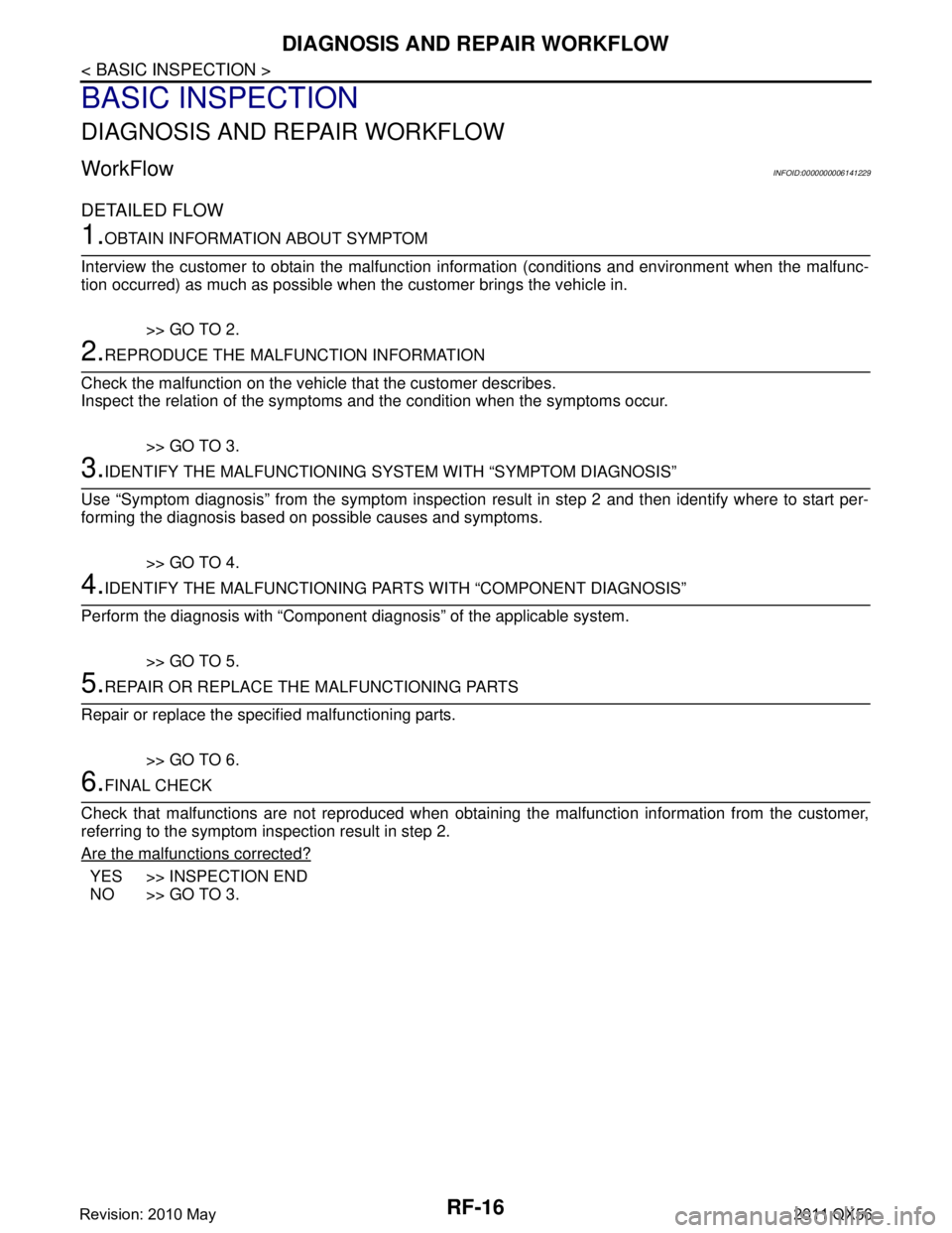
DIAGNOSIS AND REPAIR WORKFLOW
BASIC INSPECTION
DIAGNOSIS AND REPAIR WORKFLOW
WorkFlowINFOID:0000000006141229
DETAILED FLOW
1.OBTAIN INFORMATION ABOUT SYMPTOM
Interview the customer to obtain the malfunction information (conditions and environment when the malfunc-
tion occurred) as much as possible when the customer brings the vehicle in.
>> GO TO 2.
2.REPRODUCE THE MALFUNCTION INFORMATION
Check the malfunction on the vehicle that the customer describes.
Inspect the relation of the symptoms and the condition when the symptoms occur.
>> GO TO 3.
3.IDENTIFY THE MALFUNCTIONING SYS TEM WITH “SYMPTOM DIAGNOSIS”
Use “Symptom diagnosis” from the symptom inspection re sult in step 2 and then identify where to start per-
forming the diagnosis based on possible causes and symptoms.
>> GO TO 4.
4.IDENTIFY THE MALFUNCTIONING PART S WITH “COMPONENT DIAGNOSIS”
Perform the diagnosis with “Component diagnosis” of the applicable system.
>> GO TO 5.
5.REPAIR OR REPLACE THE MALFUNCTIONING PARTS
Repair or replace the specified malfunctioning parts.
>> GO TO 6.
6.FINAL CHECK
Check that malfunctions are not reproduced when obtaini ng the malfunction information from the customer,
referring to the symptom inspection result in step 2.
Are the malfunctions corrected?
YES >> INSPECTION END
NO >> GO TO 3.
Revision: 2010 May2011 QX56