2011 INFINITI QX56 lock
[x] Cancel search: lockPage 5001 of 5598
ST-14
< BASIC INSPECTION >
STEERING WHEEL
STEERING WHEEL
InspectionINFOID:0000000006225584
NEUTRAL POSITION STEERING WHEEL
1. Check that steering gear assembly, steering column assembly and steering wheel are installed in the cor-
rect position.
2. Perform neutral position inspection after wheel alignment. Refer to FSU-7, "
Inspection".
3. Set vehicle to the straight-ahead position and c onfirm steering wheel is in the neutral position.
4. Loosen outer socket lock nut and turn inner socket to left and right equally to make fine adjustments if steering wheel is not in the neutral position.
STEERING WHEEL TURNING FORCE
1. Park vehicle on a level and dry surface, set parking brake.
2. Tires need to be inflated the specified pressure. Refer to WT-69, "
Tire Air Pressure".
3. Start the engine.
4. Bring power steering fluid up to adequate operating temperature.
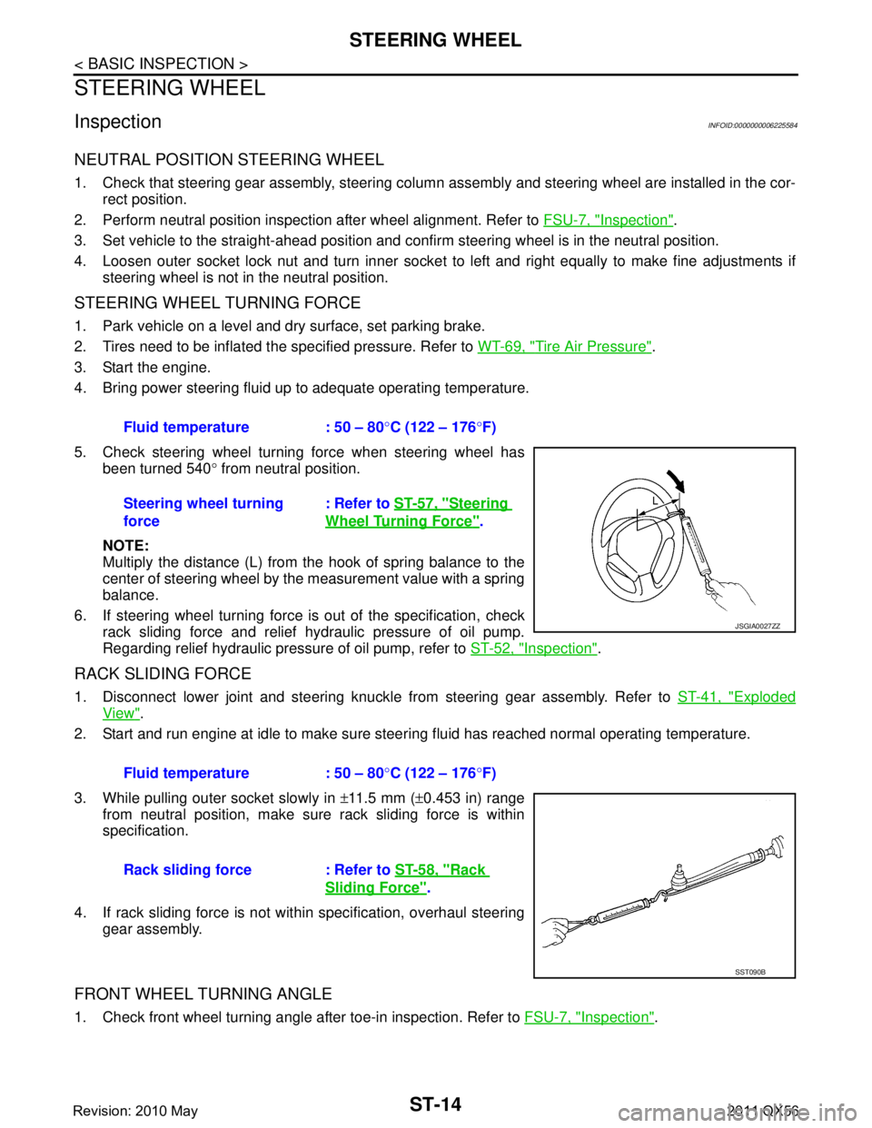
5. Check steering wheel turning force when steering wheel has been turned 540 ° from neutral position.
NOTE:
Multiply the distance (L) from the hook of spring balance to the
center of steering wheel by the measurement value with a spring
balance.
6. If steering wheel turning force is out of the specification, check
rack sliding force and relief hydraulic pressure of oil pump.
Regarding relief hydraulic pressure of oil pump, refer to ST-52, "
Inspection".
RACK SLIDING FORCE
1. Disconnect lower joint and steering knuckle from steering gear assembly. Refer to ST-41, "Exploded
View".
2. Start and run engine at idle to make sure steer ing fluid has reached normal operating temperature.
3. While pulling outer socket slowly in ±11.5 mm ( ±0.453 in) range
from neutral position, make sure rack sliding force is within
specification.
4. If rack sliding force is not within specification, overhaul steering gear assembly.
FRONT WHEEL TURNING ANGLE
1. Check front wheel turning angle after toe-in inspection. Refer to FSU-7, "Inspection".
Fluid temperature : 50 – 80
°C (122 – 176 °F)
Steering wheel turning
force : Refer to
ST-57, "
Steering
Wheel Turning Force".
JSGIA0027ZZ
Fluid temperature : 50 – 80 °C (122 – 176 °F)
Rack sliding force : Refer to ST-58, "
Rack
Sliding Force".
SST090B
Revision: 2010 May2011 QX56
Page 5005 of 5598
ST-18
< DTC/CIRCUIT DIAGNOSIS >
HEATED STEERING WHEEL SYSTEM
Is the inspection result normal?
YES >> GO TO 9.
NO >> Repair or replace damaged parts.
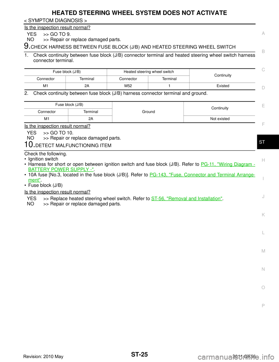
9.CHECK HARNESS BETWEEN FUSE BLOCK (J/B) AND HEATED STEERING WHEEL SWITCH
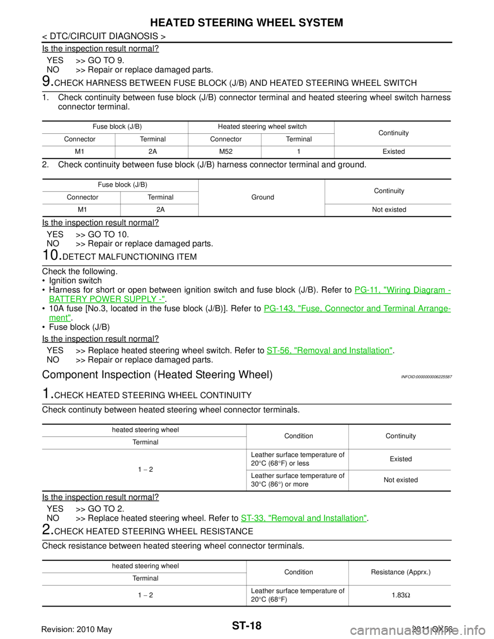
1. Check continuity between fuse block (J/B) connec tor terminal and heated steering wheel switch harness
connector terminal.
2. Check continuity between fuse block (J/B) harness connector terminal and ground.
Is the inspection result normal?
YES >> GO TO 10.
NO >> Repair or replace damaged parts.
10.DETECT MALFUNCTIONING ITEM
Check the following.
Ignition switch
Harness for short or open between ignition switch and fuse block (J/B). Refer to PG-11, "
Wiring Diagram -
BATTERY POWER SUPPLY -".
10A fuse [No.3, located in the fuse block (J/B)]. Refer to PG-143, "
Fuse, Connector and Terminal Arrange-
ment".
Fuse block (J/B)
Is the inspection result normal?
YES >> Replace heated steering wheel switch. Refer to ST-56, "Removal and Installation".
NO >> Repair or replace damaged parts.
Component Inspection (Heated Steering Wheel)INFOID:0000000006225587
1.CHECK HEATED STEERING WHEEL CONTINUITY
Check continuty between heated steering wheel connector terminals.
Is the inspection result normal?
YES >> GO TO 2.
NO >> Replace heated steering wheel. Refer to ST-33, "
Removal and Installation".
2.CHECK HEATED STEERING WHEEL RESISTANCE
Check resistance between heated steering wheel connector terminals.
Fuse block (J/B) Heated steering wheel switch Continuity
Connector Terminal Connector Terminal
M1 2A M52 1 Existed
Fuse block (J/B) GroundContinuity
Connector Terminal
M1 2A Not existed
heated steering wheel Condition Continuity
Terminal
1 − 2 Leather surface temperature of
20
°C (68 °F) or less Existed
Leather surface temperature of
30 °C (86 °) or more Not existed
heated steering wheel
Condition Resistance (Apprx.)
Terminal
1 − 2 Leather surface temperature of
20
°C (68 °F) 1.83
Ω
Revision: 2010 May2011 QX56
Page 5008 of 5598
HEATED STEERING WHEEL SWITCH INDICATOR LAMPST-21
< DTC/CIRCUIT DIAGNOSIS >
C
DE
F
H I
J
K L
M A
B
ST
N
O P
5. Check continuity between heated steering w heel relay harness connector terminal and ground.
Is the inspection result normal?
YES >> GO TO 4.
NO >> Repair or replace damaged parts.
4.CHECK HEATED STEERING WHEEL RELAY
Check heated steering wheel relay. Refer to ST-22, "
Component Inspection (Heated Steering Wheel Relay)".
Is the inspection result normal?
YES >> GO TO 5.
NO >> Replace heated steering wheel relay. Refer to ST-7, "
Component Parts Location (Heated Steering
Wheel)".
5.CHECK HARNESS BETWEEN HEATED STEERING WHEEL RELAY AND HEATED STEERING WHEEL
SWITCH
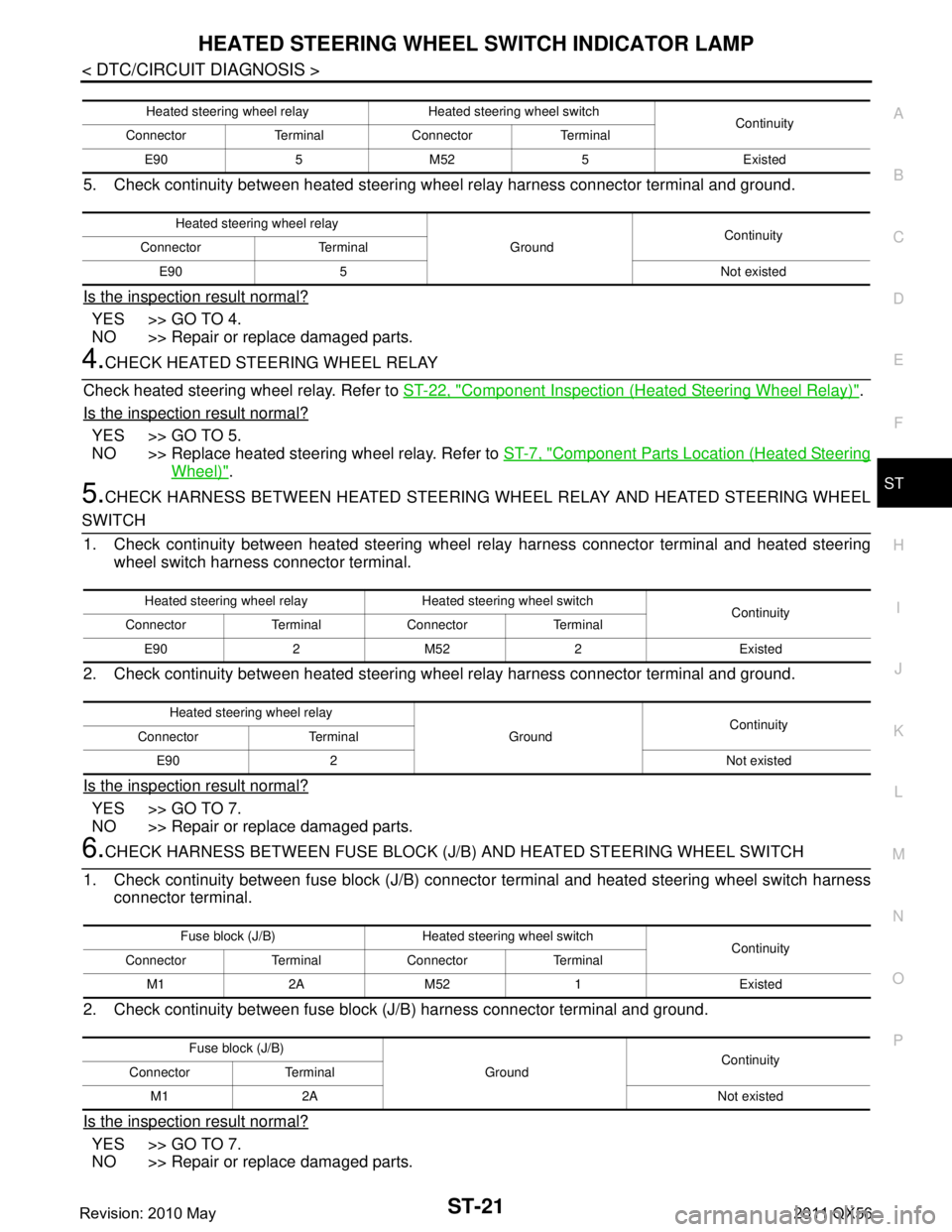
1. Check continuity between heated steering wheel relay harness connector terminal and heated steering
wheel switch harness connector terminal.
2. Check continuity between heated steering w heel relay harness connector terminal and ground.
Is the inspection result normal?
YES >> GO TO 7.
NO >> Repair or replace damaged parts.
6.CHECK HARNESS BETWEEN FUSE BLOCK (J/B) AND HEATED STEERING WHEEL SWITCH
1. Check continuity between fuse block (J/B) connec tor terminal and heated steering wheel switch harness
connector terminal.
2. Check continuity between fuse block (J/B) harness connector terminal and ground.
Is the inspection result normal?
YES >> GO TO 7.
NO >> Repair or replace damaged parts.
Heated steering wheel relay Heated steering wheel switch Continuity
Connector Terminal Connector Terminal
E90 5 M52 5 Existed
Heated steering wheel relay GroundContinuity
Connector Terminal
E90 5 Not existed
Heated steering wheel relay Heated steering wheel switch Continuity
Connector Terminal Connector Terminal
E90 2 M52 2 Existed
Heated steering wheel relay GroundContinuity
Connector Terminal
E90 2 Not existed
Fuse block (J/B) Heated steering wheel switch Continuity
Connector Terminal Connector Terminal
M1 2A M52 1 Existed
Fuse block (J/B) GroundContinuity
Connector Terminal
M1 2A Not existed
Revision: 2010 May2011 QX56
Page 5009 of 5598
ST-22
< DTC/CIRCUIT DIAGNOSIS >
HEATED STEERING WHEEL SWITCH INDICATOR LAMP
7.DETECT MALFUNCTIONING ITEM
Check the following.
Ignition switch
Harness for short or open between ignition switch and fuse block (J/B). Refer to PG-11, "
Wiring Diagram -
BATTERY POWER SUPPLY -".
10A fuse [No.3, located in the fuse block (J/B)]. Refer to PG-143, "
Fuse, Connector and Terminal Arrange-
ment".
Fuse block (J/B)
Is the inspection result normal?
YES >> Replace heated steering wheel switch. Refer to ST-56, "Removal and Installation".
NO >> Repair or replace damaged parts.
Component Inspection (H eated Steering Wheel Relay)INFOID:0000000006225591
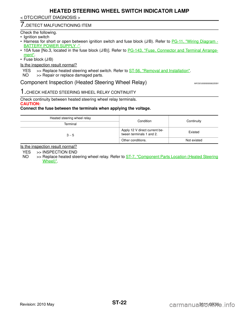
1.CHECK HEATED STEERING WHEEL RELAY CONTINUITY
Check continuity between heated steering wheel relay terminals.
CAUTION:
Connect the fuse between the termi nals when applying the voltage.
Is the inspection result normal?
YES >> INSPECTION END
NO >> Replace heated steering wheel relay. Refer to ST-7, "
Component Parts Location (Heated Steering
Wheel)".
Heated steering wheel relay
Condition Continuity
Terminal
3 − 5 Apply 12 V direct current be-
tween terminals 1 and 2.
Existed
Other conditions. Not existed
Revision: 2010 May2011 QX56
Page 5012 of 5598
HEATED STEERING WHEEL SYSTEM DOES NOT ACTIVATE
ST-25
< SYMPTOM DIAGNOSIS >
C
D E
F
H I
J
K L
M A
B
ST
N
O P
Is the inspection result normal?
YES >> GO TO 9.
NO >> Repair or replace damaged parts.
9.CHECK HARNESS BETWEEN FUSE BLOCK (J/B) AND HEATED STEERING WHEEL SWITCH
1. Check continuity between fuse block (J/B) connec tor terminal and heated steering wheel switch harness
connector terminal.
2. Check continuity between fuse block (J/B) harness connector terminal and ground.
Is the inspection result normal?
YES >> GO TO 10.
NO >> Repair or replace damaged parts.
10.DETECT MALFUNCTIONING ITEM
Check the following.
Ignition switch
Harness for short or open between ignition s witch and fuse block (J/B). Refer to PG-11, "
Wiring Diagram -
BATTERY POWER SUPPLY -".
10A fuse [No.3, located in the fuse block (J/B)]. Refer to PG-143, "
Fuse, Connector and Terminal Arrange-
ment".
Fuse block (J/B)
Is the inspection result normal?
YES >> Replace heated steering wheel switch. Refer to ST-56, "Removal and Installation".
NO >> Repair or replace damaged parts.
Fuse block (J/B) Heated steering wheel switch Continuity
Connector Terminal Connector Terminal
M1 2A M52 1 Existed
Fuse block (J/B) GroundContinuity
Connector Terminal
M1 2A Not existed
Revision: 2010 May2011 QX56
Page 5014 of 5598
HEATED STEERING WHEEL SWITCH INDICATOR LAMP DOES NOT TURN ON
ST-27
< SYMPTOM DIAGNOSIS >
C
D E
F
H I
J
K L
M A
B
ST
N
O P
Is the inspection result normal?
YES >> GO TO 4.
NO >> Repair or replace damaged parts.
4.CHECK HEATED STEERING WHEEL RELAY
Check heated steering wheel relay. Refer to ST-22, "
Component Inspection (Heated Steering Wheel Relay)".
Is the inspection result normal?
YES >> GO TO 5.
NO >> Replace heated steering wheel relay. Refer to ST-7, "
Component Parts Location (Heated Steering
Wheel)".
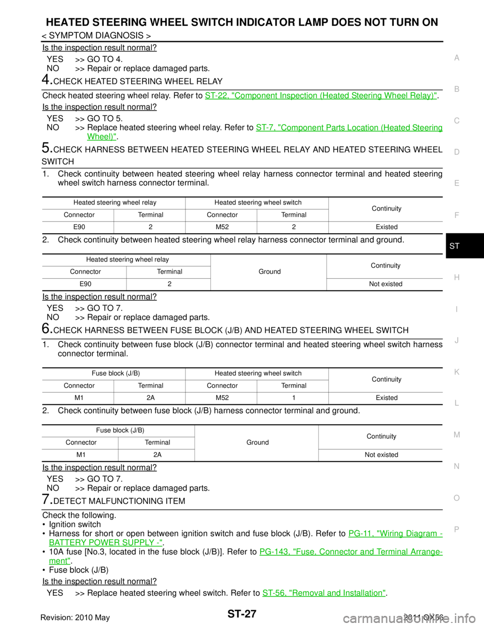
5.CHECK HARNESS BETWEEN HEATED STEERING WHEEL RELAY AND HEATED STEERING WHEEL
SWITCH
1. Check continuity between heated steering wheel relay harness connector terminal and heated steering
wheel switch harness connector terminal.
2. Check continuity between heated steering w heel relay harness connector terminal and ground.
Is the inspection result normal?
YES >> GO TO 7.
NO >> Repair or replace damaged parts.
6.CHECK HARNESS BETWEEN FUSE BLOCK (J/B) AND HEATED STEERING WHEEL SWITCH
1. Check continuity between fuse block (J/B) connec tor terminal and heated steering wheel switch harness
connector terminal.
2. Check continuity between fuse block (J/B) harness connector terminal and ground.
Is the inspection result normal?
YES >> GO TO 7.
NO >> Repair or replace damaged parts.
7.DETECT MALFUNCTIONING ITEM
Check the following.
Ignition switch
Harness for short or open between ignition s witch and fuse block (J/B). Refer to PG-11, "
Wiring Diagram -
BATTERY POWER SUPPLY -".
10A fuse [No.3, located in the fuse block (J/B)]. Refer to PG-143, "
Fuse, Connector and Terminal Arrange-
ment".
Fuse block (J/B)
Is the inspection result normal?
YES >> Replace heated steering wheel switch. Refer to ST-56, "Removal and Installation".
Heated steering wheel relay Heated steering wheel switch
Continuity
Connector Terminal Connector Terminal
E90 2 M52 2 Existed
Heated steering wheel relay GroundContinuity
Connector Terminal
E90 2 Not existed
Fuse block (J/B) Heated steering wheel switch Continuity
Connector Terminal Connector Terminal
M1 2A M52 1 Existed
Fuse block (J/B) GroundContinuity
Connector Terminal
M1 2A Not existed
Revision: 2010 May2011 QX56
Page 5016 of 5598
NOISE, VIBRATION AND HARSHNESS (NVH) TROUBLESHOOTINGST-29
< SYMPTOM DIAGNOSIS >
C
DE
F
H I
J
K L
M A
B
ST
N
O P
NOISE, VIBRATION AND HARSHN ESS (NVH) TROUBLESHOOTING
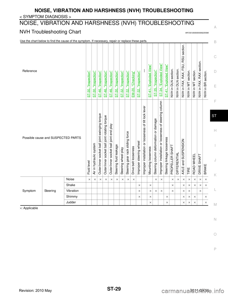
NVH Troubleshooting ChartINFOID:0000000006225596
Use the chart below to find the cause of the symp tom. If necessary, repair or replace these parts.
×: ApplicableReference
ST-30, "
Inspection
"
ST-30, "
Inspection
"
ST-46, "
Inspection
"
ST-46, "
Inspection
"
ST-46, "
Inspection
"
ST-30, "
Inspection
"
ST-32, "
Inspection
"
ST-32, "
Inspection
"
EM-20, "
Checking
"
ST-32, "
Inspection
"—
ST-41, "
Exploded View
"
ST-35, "
Inspection
"
ST-34, "
Exploded View
"
ST-41, "
Exploded View
"
NVH in DLN section.
NVH in DLN section.
NVH in FAX, RAX, FSU, RSU section.
NVH in WT section.
NVH in WT section.
NVH in FAX, RAX section.
NVH in BR section.
Possible cause and SUSPECTED PARTS
Fluid level
Air in hydraulic system
Outer/inner socket ball joint swinging torque
Outer/inner socket ball joint rotating torque
Outer/inner socket ball joint end play
Steering fluid leakage
Steering wheel play
Steering gear rack sliding force
Drive belt looseness
Improper steering wheel
Improper installation or looseness of tilt lock lever
Mounting looseness
Steering column deformation or damage
Improper installation or looseness of steering column
Steering linkage looseness
PROPELLER SHAFT
DIFFERENTIAL
AXLE and SUSPENSION
TIRE
ROAD WHEEL
DRIVE SHAFT
BRAKE
Symptom Steering Noise
××××××××× ×× ×××××××
Shake × × × ×××××
Vibration ××××××××
Shimmy ×× × ××××
Judder ××××××
Revision: 2010 May2011 QX56
Page 5017 of 5598
ST-30
< PERIODIC MAINTENANCE >
POWER STEERING FLUID
PERIODIC MAINTENANCE
POWER STEERING FLUID
InspectionINFOID:0000000006225597
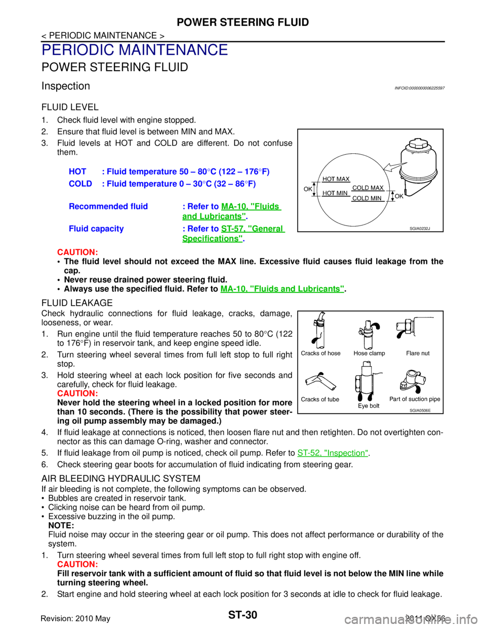
FLUID LEVEL
1. Check fluid level with engine stopped.
2. Ensure that fluid level is between MIN and MAX.
3. Fluid levels at HOT and COLD are different. Do not confuse
them.
CAUTION:
The fluid level should not exceed the MAX line. Excessive flui d causes fluid leakage from the
cap.
Never reuse drained power steering fluid.
Always use the specified fluid. Refer to MA-10, "
Fluids and Lubricants".
FLUID LEAKAGE
Check hydraulic connections for fluid leakage, cracks, damage,
looseness, or wear.
1. Run engine until the fluid temperature reaches 50 to 80 °C (122
to 176 °F) in reservoir tank, and keep engine speed idle.
2. Turn steering wheel several times from full left stop to full right stop.
3. Hold steering wheel at each lock position for five seconds and carefully, check for fluid leakage.
CAUTION:
Never hold the steering wheel in a locked position for more
than 10 seconds. (There is the possibility that power steer-
ing oil pump assembly may be damaged.)
4. If fluid leakage at connections is noticed, then loos en flare nut and then retighten. Do not overtighten con-
nector as this can damage O-ring, washer and connector.
5. If fluid leakage from oil pump is noticed, check oil pump. Refer to ST-52, "
Inspection".
6. Check steering gear boots for accumulation of fluid indicating from steering gear.
AIR BLEEDING HYDRAULIC SYSTEM
If air bleeding is not complete, the following symptoms can be observed.
Bubbles are created in reservoir tank.
Clicking noise can be heard from oil pump.
Excessive buzzing in the oil pump. NOTE:
Fluid noise may occur in the steering gear or oil pump. This does not affect performance or durability of the
system.
1. Turn steering wheel several times from full left stop to full right stop with engine off. CAUTION:
Fill reservoir tank with a sufficien t amount of fluid so that fluid level is not below the MIN line while
turning steering wheel.
2. Start engine and hold steering wheel at each lock position for 3 seconds at idle to check for fluid leakage.
HOT : Fluid temperature 50 – 80
°C (122 – 176 °F)
COLD : Fluid temperature 0 – 30 °C (32 – 86 °F)
Recommended fluid : Refer to MA-10, "
Fluids
and Lubricants".
Fluid capacity : Refer to ST-57, "
General
Specifications".
SGIA0232J
SGIA0506E
Revision: 2010 May2011 QX56