2011 INFINITI QX56 lock
[x] Cancel search: lockPage 4765 of 5598
SR-2
< PRECAUTION >
PRECAUTIONS
PRECAUTION
PRECAUTIONS
Precaution for Supplemental Restraint System (SRS) "AIR BAG" and "SEAT BELT
PRE-TENSIONER"
INFOID:0000000006113043
The Supplemental Restraint System such as “A IR BAG” and “SEAT BELT PRE-TENSIONER”, used along
with a front seat belt, helps to reduce the risk or severi ty of injury to the driver and front passenger for certain
types of collision. This system includes seat belt switch inputs and dual stage front air bag modules. The SRS
system uses the seat belt switches to determine the front air bag deployment, and may only deploy one front
air bag, depending on the severity of a collision and w hether the front occupants are belted or unbelted.
Information necessary to service the system safely is included in the “SRS AIR BAG” and “SEAT BELT” of this
Service Manual.
WARNING:
• To avoid rendering the SRS inopera tive, which could increase the risk of personal injury or death in
the event of a collision that would result in air bag inflation, all maintenance must be performed by
an authorized NISS AN/INFINITI dealer.
Improper maintenance, including in correct removal and installation of the SRS, can lead to personal
injury caused by unintent ional activation of the system. For re moval of Spiral Cable and Air Bag
Module, see the “SRS AIR BAG”.
Do not use electrical test equipmen t on any circuit related to the SRS unless instructed to in this
Service Manual. SRS wiring harnesses can be identi fied by yellow and/or orange harnesses or har-
ness connectors.
PRECAUTIONS WHEN USING POWER TOOLS (AIR OR ELECTRIC) AND HAMMERS
WARNING:
When working near the Air Bag Diagnosis Sensor Unit or other Air Bag System sensors with the ignition ON or engine running, DO NOT use air or electric power tools or strike near the sensor(s)
with a hammer. Heavy vibration could activate the sensor(s) and deploy the air bag(s), possibly
causing serious injury.
When using air or electric power tools or hammers , always switch the ignition OFF, disconnect the
battery, and wait at least 3 minu tes before performing any service.
Precaution Necessary for Steering W heel Rotation after Battery Disconnect
INFOID:0000000006113044
NOTE:
Before removing and installing any control units, first tu rn the push-button ignition switch to the LOCK posi-
tion, then disconnect bot h battery cables.
After finishing work, confirm that all control unit connectors are connected properly, then re-connect both
battery cables.
Always use CONSULT-III to perform self-diagnosis as a part of each function inspection after finishing work.
If a DTC is detected, perform trouble diagnos is according to self-diagnosis results.
For vehicle with steering lock unit, if the battery is disconnected or discharged, the steering wheel will lock and
cannot be turned.
If turning the steering wheel is required with the bat tery disconnected or discharged, follow the operation pro-
cedure below before starting the repair operation.
OPERATION PROCEDURE
1. Connect both battery cables. NOTE:
Supply power using jumper cables if battery is discharged.
2. Turn the push-button ignition switch to ACC position. (At this time, the steering lock will be released.)
3. Disconnect both battery cables. The steering lock wi ll remain released with both battery cables discon-
nected and the steering wheel can be turned.
4. Perform the necessary repair operation.
Revision: 2010 May2011 QX56
Page 4766 of 5598
PRECAUTIONSSR-3
< PRECAUTION >
C
DE
F
G
I
J
K L
M A
B
SR
N
O P
5. When the repair work is completed, re-connect both battery cables. With the brake pedal released, turn
the push-button ignition switch from ACC position to ON position, then to LOCK position. (The steering
wheel will lock when the push-button ignition switch is turned to LOCK position.)
6. Perform self-diagnosis check of a ll control units using CONSULT-III.
Precaution for Battery ServiceINFOID:0000000006113045
Before disconnecting the battery, lower both the driver and passenger windows. This will prevent any interfer-
ence between the window edge and the vehicle when the door is opened/closed. During normal operation, the
window slightly raises and lowers automatically to prev ent any window to vehicle interference. The automatic
window function will not work with the battery disconnected.
Occupant Classification SystemINFOID:0000000006113047
Replace occupant classification system control uni t and passenger front seat cushion as an assembly.
Refer to SE-105, "
Exploded View".
ServiceINFOID:0000000006113046
Never use electrical test equipment to check SRS circuits unless instructed to in this Service Manual.
Before servicing the SRS, turn ignition switch OFF, disconnect battery negative terminal and wait at least 3
minutes.
For approximately 3 minutes after the battery negative termi nal is removed, it is still possible for the air bag
and seat belt pre-tensioner to deploy. Therefore, never work on any SRS connectors or wires until at least 3
minutes have elapsed.
Diagnosis sensor unit must always be installed with their arrow marks “ ⇐” pointing towards the front of the
vehicle for proper operation. Also check diagnosis sensor unit for cracks, deformities, or rust before installa-
tion and replace as required.
The spiral cable must be aligned in the neutral position since its rotations are limited. Never turn steering
wheel and column after removal of steering gear.
Handle air bag module carefully. Always place driver and front passenger air bag modules with the pad side facing upward and seat mounted front side air bag m odule standing with the stud bolt side facing downward.
Perform self-diagnosis to check entire SRS fo r proper function after replacing any components.
After air bag deploys, the front instrument panel assembly should be replaced if damaged.
Always replace instrument panel pad following front passenger air bag deployment.
Revision: 2010 May2011 QX56
Page 4775 of 5598
SR-12
< REMOVAL AND INSTALLATION >
DRIVER AIR BAG MODULE
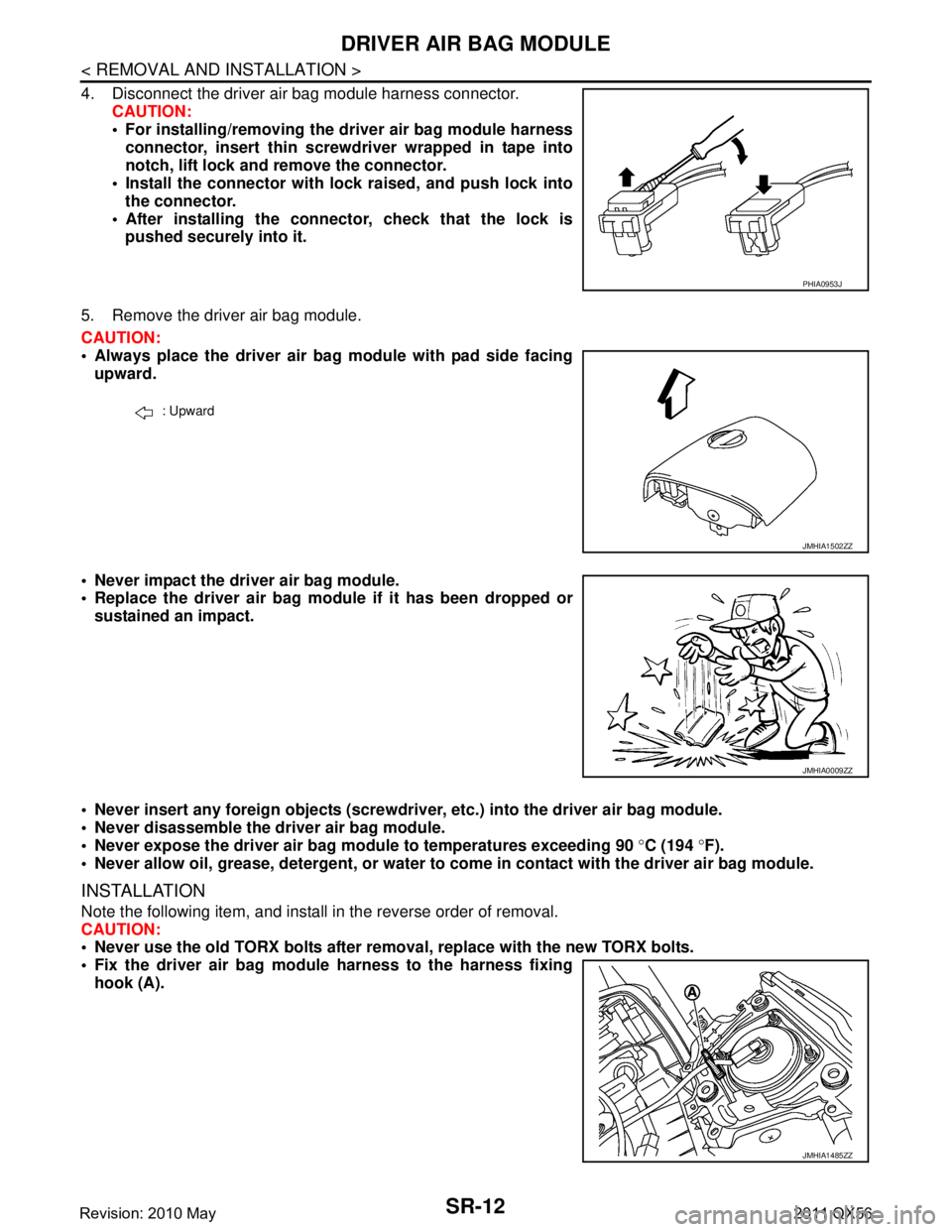
4. Disconnect the driver air bag module harness connector.CAUTION:
For installing/removing the driver air bag module harnessconnector, insert thin screwdriver wrapped in tape into
notch, lift lock and remove the connector.
Install the connector with lock raised, and push lock into
the connector.
After installing the conn ector, check that the lock is
pushed securely into it.
5. Remove the driver air bag module.
CAUTION:
Always place the driver air bag module with pad side facing upward.
Never impact the driver air bag module.
Replace the driver air bag modu le if it has been dropped or
sustained an impact.
Never insert any foreign objects (screwdriver , etc.) into the driver air bag module.
Never disassemble the driver air bag module.
Never expose the driver air bag module to temperatures exceeding 90 °C (194 °F).
Never allow oil, grease, detergent, or water to come in contact with the driver air bag module.
INSTALLATION
Note the following item, and install in the reverse order of removal.
CAUTION:
Never use the old TORX bolts after removal, replace with the new TORX bolts.
Fix the driver air bag module harness to the harness fixing hook (A).
PHIA0953J
: Upward
JMHIA1502ZZ
JMHIA0009ZZ
JMHIA1485ZZ
Revision: 2010 May2011 QX56
Page 4778 of 5598
SPIRAL CABLESR-15
< REMOVAL AND INSTALLATION >
C
DE
F
G
I
J
K L
M A
B
SR
N
O P
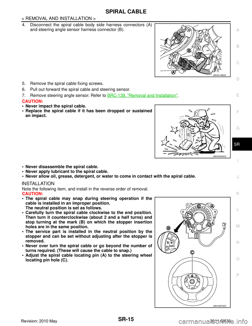
4. Disconnect the spiral cable body side harness connectors (A) and steering angle sensor harness connector (B).
5. Remove the spiral cable fixing screws.
6. Pull out forward the spiral cable and steering sensor.
7. Remove steering angle sensor. Refer to BRC-139, "
Removal and Installation".
CAUTION:
Never impact the spiral cable.
Replace the spiral cable if it has been dropped or sustained
an impact.
Never disassemble the spiral cable.
Never apply lubricant to the spiral cable.
Never allow oil, grease, detergent, or water to come in contact with the spiral cable.
INSTALLATION
Note the following item, and install in the reverse order of removal.
CAUTION:
The spiral cable may snap during steering operation if the
cable is installed in an improper position.
The neutral position is set as follows.
Carefully turn the spiral cable clockwise to the end position.
Then turn it counterclockwise (a bout 2 and a half turns) and
stop turning at the mark (B) on which the stopper insertion
holes are in the same position.
The service part is installed in the neutral position by the
stopper and can be set without adjusting after the stopper is
removed.
Never over turn the spiral cable or go beyond the number of
turns required. (These will cause the cable to snap.)
Adjust the spiral cable locatin g pin (A) to the steering wheel
locating pin hole (C).
JMHIA1486ZZ
JMHIA0009ZZ
JMHIA0879ZZ
Revision: 2010 May2011 QX56
Page 4783 of 5598
SR-20
< REMOVAL AND INSTALLATION >
SIDE CURTAIN AIR BAG MODULE
For installing/removing the side curtain air bag moduleharness connector, insert thin screwdriver wrapped in
tape into notch, lift lock and remove the connector.
Install the connector with lock raised, and push lock into
the connector.
After installing the conn ector, check that the lock is
pushed securely into it.
3. Remove the side curtain air bag module fixing bolts, and then remove the side curtain air bag module.
CAUTION:
Never impact the side curtain air bag module.
Replace the side curtain air bag module if it has been dropped
or sustained an impact.
Never insert any foreign objects (screwdriver, etc.) into the side curtain air bag module.
Never disassemble the side curtain air bag module.
Never expose the side curtain air ba g module to temperatures exceeding 90 °C (194 °F).
Never allow oil, grease, detergent, or water to come in contact with the side curtain air bag module.
INSTALLATION
Note the following item, and install in the reverse order of removal.
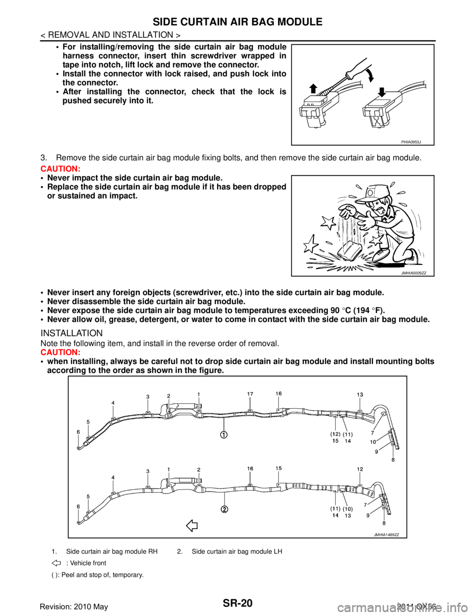
CAUTION:
when installing, always be careful not to drop side curtain air bag module and install mounting bolts
according to the order as shown in the figure.
PHIA0953J
JMHIA0009ZZ
1. Side curtain air bag module RH 2. Side curtain air bag module LH
: Vehicle front
( ): Peel and stop of, temporary.
JMHIA1489ZZ
Revision: 2010 May2011 QX56
Page 4986 of 5598
SRS AIR BAG WARNING LAMP DOES NOT TURN OFF
SRC-193
< SYMPTOM DIAGNOSIS >
C
D E
F
G
I
J
K L
M A
B
SRC
N
O P
SYMPTOM DIAGNOSIS
SRS AIR BAG WARNING LAMP DOES NOT TURN OFF
Diagnosis ProcedureINFOID:0000000006220157
1.CHECK AIR BAG MODULE AND SEAT BELT PRE-TENSIONER
Check the deployment of air bag m odule and seat belt pre-tensioner.
Is air bag module deployed?
YES >> Replace the malfunctioning parts.
NO >> GO TO 2.
2.CHECK AIR BAG FUSE
Check 10 A fuse [No.2, located in fuse block (J/B)].
Is the inspection result normal?
YES >> GO TO 3.
NO >> Replace the fuse.
3.CHECK HARNESS CONNECTOR
Check the harness connector.
Is the inspection result normal?
YES >> GO TO 4.
NO >> Replace harness connectors.
4.CHECK WIRING HARNESS
Check the wiring harness externals.
Is the inspection result normal?
YES >> GO TO 5.
NO >> Replace wiring harness.
5.REPLACE AIR BAG DIAGNOSIS SENSOR UNIT
1. Replace air bag diagnosis sensor unit. Refer to SR-26, "
Removal and Installation".
2. Check air bag warning lamp operation.
Is the inspection result normal?
YES >> INSPECTION END
NO >> GO TO 6.
6.REPLACE COMBINATION METER
1. Replace combination meter. Refer to MWI-85, "
Removal and Installation".
2. Check air bag warning lamp operation.
Is the inspection result normal?
YES >> INSPECTION END
NO >> GO TO 1.
Revision: 2010 May2011 QX56
Page 4990 of 5598
PRECAUTIONSST-3
< PRECAUTION >
C
DE
F
H I
J
K L
M A
B
ST
N
O P
PRECAUTION
PRECAUTIONS
Precaution for Supplemental Restraint System (SRS) "AIR BAG" and "SEAT BELT
PRE-TENSIONER"
INFOID:0000000006272045
The Supplemental Restraint System such as “A IR BAG” and “SEAT BELT PRE-TENSIONER”, used along
with a front seat belt, helps to reduce the risk or severi ty of injury to the driver and front passenger for certain
types of collision. This system includes seat belt switch inputs and dual stage front air bag modules. The SRS
system uses the seat belt switches to determine the front air bag deployment, and may only deploy one front
air bag, depending on the severity of a collision and whether the front occupants are belted or unbelted.
Information necessary to service the system safely is included in the “SRS AIR BAG” and “SEAT BELT” of this
Service Manual.
WARNING:
• To avoid rendering the SRS inoper ative, which could increase the risk of personal injury or death in
the event of a collision that would result in air ba g inflation, all maintenance must be performed by
an authorized NISSAN/INFINITI dealer.
Improper maintenance, including in correct removal and installation of the SRS, can lead to personal
injury caused by unintentional act ivation of the system. For removal of Spiral Cable and Air Bag
Module, see the “SRS AIR BAG”.
Do not use electrical test equipm ent on any circuit related to the SRS unless instructed to in this
Service Manual. SRS wiring harnesses can be identi fied by yellow and/or orange harnesses or har-
ness connectors.
PRECAUTIONS WHEN USING POWER TOOLS (AIR OR ELECTRIC) AND HAMMERS
WARNING:
When working near the Air Bag Diagnosis Sensor Unit or other Air Bag System sensors with the
ignition ON or engine running, DO NOT use air or electric power tools or strike near the sensor(s)
with a hammer. Heavy vibration could activate the sensor(s) and deploy the air bag(s), possibly
causing serious injury.
When using air or electric power tools or hammers , always switch the ignition OFF, disconnect the
battery, and wait at least 3 minutes before performing any service.
Precaution Necessary for Steering Wh eel Rotation after Battery Disconnect
INFOID:0000000006272046
NOTE:
Before removing and installing any control units, first tu rn the push-button ignition switch to the LOCK posi-
tion, then disconnect both battery cables.
After finishing work, confirm that all control unit connectors are connected properly, then re-connect both
battery cables.
Always use CONSULT-III to perform self-diagnosis as a part of each function inspection after finishing work.
If a DTC is detected, perform trouble diagnos is according to self-diagnosis results.
For vehicle with steering lock unit, if the battery is disconnected or discharged, the steering wheel will lock and
cannot be turned.
If turning the steering wheel is required with the batte ry disconnected or discharged, follow the operation pro-
cedure below before starting the repair operation.
OPERATION PROCEDURE
1. Connect both battery cables. NOTE:
Supply power using jumper cables if battery is discharged.
2. Turn the push-button ignition switch to ACC position. (At this time, the steering lock will be released.)
3. Disconnect both battery cables. The steering lock wil l remain released with both battery cables discon-
nected and the steering wheel can be turned.
4. Perform the necessary repair operation.
Revision: 2010 May2011 QX56
Page 4991 of 5598

ST-4
< PRECAUTION >
PRECAUTIONS
5. When the repair work is completed, re-connect both battery cables. With the brake pedal released, turn
the push-button ignition switch from ACC position to ON position, then to LOCK position. (The steering
wheel will lock when the push-button igniti on switch is turned to LOCK position.)
6. Perform self-diagnosis check of all control units using CONSULT-III.
Service Notice or Precautions for Steering SystemINFOID:0000000006225573
In case of removing steering gear assembly, make the final tightening with grounded and unloaded vehicle condition, and then check wheel alignment.
Observe the following precautions when disassembling.
- Before disassembly, thoroughly clean the outside of the unit.
- Disassembly should be done in a clean work area. It is im portant to prevent the internal parts from becoming
contaminated by dirt or other foreign matter.
- For easier and proper assembly, place disassembled parts in order on a parts rack.
- Use nylon cloth or paper towels to clean the parts; co mmon shop rags can leave lint that might interfere with
their operation.
- Never reuse non-reusable parts.
- Before assembling, apply the specified grease to the directed parts.
Revision: 2010 May2011 QX56