Page 5368 of 5598
![INFINITI QX56 2011 Factory Service Manual
TM-280
< UNIT DISASSEMBLY AND ASSEMBLY >[7AT: RE7R01B]
UNDER DRIVE CARRIER
, FRONT BRAKE HUB
3. Remove snap ring (1) from front brake hub using a flat-bladed
screwdriver.
CAUTION:
Be careful not to INFINITI QX56 2011 Factory Service Manual
TM-280
< UNIT DISASSEMBLY AND ASSEMBLY >[7AT: RE7R01B]
UNDER DRIVE CARRIER
, FRONT BRAKE HUB
3. Remove snap ring (1) from front brake hub using a flat-bladed
screwdriver.
CAUTION:
Be careful not to](/manual-img/42/57033/w960_57033-5367.png)
TM-280
< UNIT DISASSEMBLY AND ASSEMBLY >[7AT: RE7R01B]
UNDER DRIVE CARRIER
, FRONT BRAKE HUB
3. Remove snap ring (1) from front brake hub using a flat-bladed
screwdriver.
CAUTION:
Be careful not to scratch front brake hub.
Be careful not to damage snap ring.
AssemblyINFOID:0000000006226926
1. Install snap ring (1) to front brake hub.CAUTION:
Be careful not to damage snap ring.
2. Install under drive carrier assembly (1) to front brake hub.
3. Install snap ring (1) to front brake hub using a flat-bladed screw- driver.
CAUTION:
Be careful not to scratch front brake hub.
Be careful not to damage snap ring.
InspectionINFOID:0000000006226927
INSPECTION AFTER REMOVAL
Each Snap Ring
Check for deformation, fatigue or damage. If necessary, replace snap ring.
Under Drive Carrier Assembly
Check for deformation, fatigue or damage. If nec essary, replace under drive carrier assembly.
Front Brake Hub
JPDIA1130ZZ
JPDIA1130ZZ
JPDIA1129ZZ
JPDIA1128ZZ
Revision: 2010 May2011 QX56
Page 5369 of 5598
UNDER DRIVE CARRIER, FRONT BRAKE HUBTM-281
< UNIT DISASSEMBLY AND ASSEMBLY > [7AT: RE7R01B]
C
EF
G H
I
J
K L
M A
B
TM
N
O P
Check for deformation, fatigue or damage. If necessary, replace front brake hub.
Revision: 2010 May2011 QX56
Page 5386 of 5598
![INFINITI QX56 2011 Factory Service Manual
TM-298
< SERVICE DATA AND SPECIFICATIONS (SDS) [7AT: RE7R01B]
SERVICE DATA AND SPECIFICATIONS (SDS)
Total End Play
INFOID:0000000006226949
Unit: mm (in)
Reverse Brake ClearanceINFOID:0000000006226950 INFINITI QX56 2011 Factory Service Manual
TM-298
< SERVICE DATA AND SPECIFICATIONS (SDS) [7AT: RE7R01B]
SERVICE DATA AND SPECIFICATIONS (SDS)
Total End Play
INFOID:0000000006226949
Unit: mm (in)
Reverse Brake ClearanceINFOID:0000000006226950](/manual-img/42/57033/w960_57033-5385.png)
TM-298
< SERVICE DATA AND SPECIFICATIONS (SDS) [7AT: RE7R01B]
SERVICE DATA AND SPECIFICATIONS (SDS)
Total End Play
INFOID:0000000006226949
Unit: mm (in)
Reverse Brake ClearanceINFOID:0000000006226950
Unit: mm (in)
Front Brake ClearanceINFOID:0000000006226951
Unit: mm (in)
2346 Brake ClearanceINFOID:0000000006226952
Unit: mm (in)
Total end play Standard 0.25 – 0.55 (0.0098 – 0.0217)
Thickness of bearing race for adjusting total end play 1.0 (0.039)
1.2 (0.047)
1.4 (0.055)
1.6 (0.063)
1.8 (0.071)
2.0 (0.079)
2.2 (0.087)
Reverse brake clearance Standard 0.8 – 1.2 (0.031 – 0.047)
Thickness of retaining plate for adjusting reverse brake clearance4.8 (0.189)
5.0 (0.197)
5.2 (0.205)
5.4 (0.213)
5.6 (0.220)
5.8 (0.228)
6.0 (0.236)
Front brake clearance Standard 0.7 – 1.1 (0.028 – 0.043)
Thickness of retaining plate for adjusting front brake clearance
2.0 (0.079)
2.2 (0.087)
2.4 (0.094)
2.6 (0.102)
2.8 (0.110)
2346 brake clearance Standard 1.5 – 1.9 (0.059 – 0.075)
Thickness of snap ring for adjusting 2346 brake clearance 2.0 (0.079)
2.2 (0.087)
2.4 (0.094)
2.6 (0.102)
2.8 (0.110)
3.0 (0.118)
Revision: 2010 May2011 QX56
Page 5390 of 5598
VTL-4
< PRECAUTION >
PRECAUTIONS
5. When the repair work is completed, re-connect both battery cables. With the brake pedal released, turn
the push-button ignition switch from ACC position to ON position, then to LOCK position. (The steering
wheel will lock when the push-button igniti on switch is turned to LOCK position.)
6. Perform self-diagnosis check of all control units using CONSULT-III.
Revision: 2010 May2011 QX56
Page 5405 of 5598

WCS
WCS-1
DRIVER INFORMATION & MULTIMEDIA
C
DE
F
G H
I
J
K L
M B
SECTION WCS
A
O P
CONTENTS
WARNING CHIME SYSTEM
PRECAUTION ................ ...............................3
PRECAUTIONS .............................................. .....3
Precaution for Supplemental Restraint System
(SRS) "AIR BAG" and "SEAT BELT PRE-TEN-
SIONER" ............................................................. ......
3
SYSTEM DESCRIPTION ..............................4
COMPONENT PARTS ................................... .....4
Component Parts Location .................................. ......4
Component Description .............................................4
Combination Meter ....................................................5
SYSTEM ..............................................................6
WARNING CHIME SYSTEM .......................................6
WARNING CHIME SYSTEM : System Diagram . ......6
WARNING CHIME SYSTEM : System Description
......
6
WARNING CHIME SYSTEM : Fail-Safe ...................7
LIGHT REMINDER WARNING CHIME ................. ......8
LIGHT REMINDER WARNING CHIME : System
Diagram .....................................................................
8
LIGHT REMINDER WARNING CHIME : System
Description ................................................................
8
FRONT FOG LIGHT REMINDER WARNING
CHIME .................................................................... ......
9
FRONT FOG LIGHT REMINDER WARNING
CHIME : System Diagram .......................................
10
FRONT FOG LIGHT REMINDER WARNING
CHIME : System Description ...................................
10
SEAT BELT WARNING CHIME ............................ ....10
SEAT BELT WARNING CHIME : System Diagram
....
11
SEAT BELT WARNING CHIME : System Descrip-
tion ...................................................................... ....
11
PARKING BRAKE RELEASE WARNING CHIME ....12
PARKING BRAKE RELEASE WARNING CHIME
: System Diagram ................................................ ....
12
PARKING BRAKE RELEASE WARNING CHIME
: System Description ................................................
12
DIAGNOSIS SYSTEM (COMBINATION
METER) .............................................................
14
CONSULT-III Function ............................................14
DIAGNOSIS SYSTEM (BCM) ...........................19
COMMON ITEM ..................................................... ....19
COMMON ITEM : CONSULT-III Function (BCM -
COMMON ITEM) .....................................................
19
BUZZER ................................................................. ....20
BUZZER : CONSULT-III Function (BCM - BUZZ-
ER) ..........................................................................
20
ECU DIAGNOSIS INFORMATION ..............22
COMBINATION METER ...................................22
Reference Value .................................................. ....22
Fail-Safe ..................................................................29
DTC Index ...............................................................30
BCM (BODY CONTROL MODULE) .................31
List of ECU Reference .............................................31
WIRING DIAGRAM ......................................32
WARNING CHIME SYSTEM .............................32
Wiring Diagram .................................................... ....32
BASIC INSPECTION ...................................37
DIAGNOSIS AND REPAIR WORKFLOW ........37
Work Flow ............................................................ ....37
DTC/CIRCUIT DIAGNOSIS .........................39
POWER SUPPLY AND GROUND CIRCUIT ....39
COMBINATION METER ........................................ ....39
Revision: 2010 May2011 QX56
Page 5406 of 5598

WCS-2
COMBINATION METER : Diagnosis Procedure ....39
METER BUZZER CIRCUIT ................................40
Component Function Check ................................ ...40
Diagnosis Procedure .............................................40
SEAT BELT BUCKLE SWITCH SIGNAL CIR-
CUIT ...................................................................
41
Component Function Check .............................. ...41
Diagnosis Procedure .............................................41
Component Inspection ............................................42
PARKING BRAKE SWITCH SIGNAL CIR-
CUIT ...................................................................
43
Diagnosis Procedure ........................................... ...43
Component Inspection ............................................43
SYMPTOM DIAGNOSIS ............................44
THE LIGHT REMINDER WARNING DOES
NOT SOUND ................................................... ...
44
Description ........................................................... ...44
Diagnosis Procedure ...............................................44
THE SEAT BELT WARNING CONTINUES
SOUNDING, OR DOES NOT SOUND ...............
45
Description ........................................................... ...45
Diagnosis Procedure ...............................................45
THE PARKING BRAKE RELEASE WARNING
CONTINUES SOUNDING, OR DOES NOT
SOUND ..............................................................
46
Description ........................................................... ...46
Diagnosis Procedure ...............................................46
Revision: 2010 May2011 QX56
Page 5408 of 5598

WCS-4
< SYSTEM DESCRIPTION >
COMPONENT PARTS
SYSTEM DESCRIPTION
COMPONENT PARTS
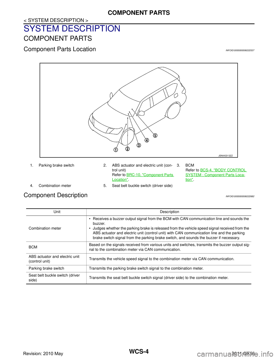
Component Parts LocationINFOID:0000000006222537
Component DescriptionINFOID:0000000006222682
1. Parking brake switch 2. ABS actuator and electric unit (con-
trol unit)
Refer to BRC-10, "
Component Parts
Location". 3. BCM
Refer to BCS-4, "
BODY CONTROL
SYSTEM : Component Parts Loca-
tion".
4. Combination meter 5. Seat belt buckle switch (driver side)
JSNIA3313ZZ
Unit Description
Combination meter Receives a buzzer output signal from the BCM with CAN communication line and sounds the
buzzer.
Judges whether the parking brake is released from the vehicle speed signal received from the ABS actuator and electric unit (control unit) with CAN commun ication line and the parking
brake switch signal from the parking brake switch, and sounds the buzzer if necessary.
BCM Based on the signals received from various units and switches, transmits the buzzer output sig-
nal to the combination meter via CAN communication.
ABS actuator and electric unit
(control unit) Transmits the vehicle speed signal to the combination meter via CAN communication.
Parking brake switch Transmits the parking brake switch signal to the combination meter.
Seat belt buckle switch (driver
side) Transmits the seat belt buckle switch signal (driver side) to the combination meter.
Revision: 2010 May2011 QX56
Page 5411 of 5598

WCS
SYSTEMWCS-7
< SYSTEM DESCRIPTION >
C
DE
F
G H
I
J
K L
M B A
O P
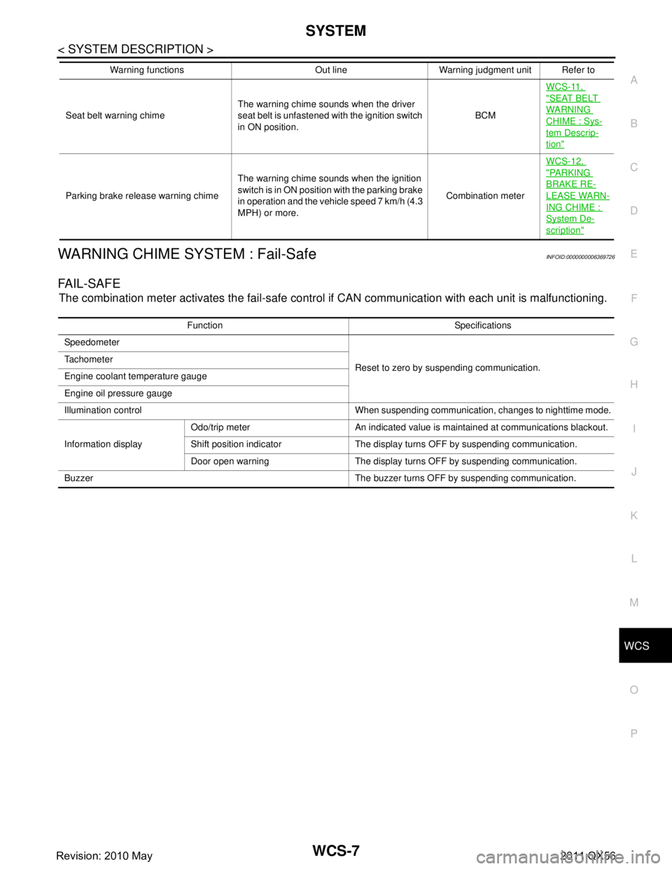
WARNING CHIME SYSTEM : Fail-SafeINFOID:0000000006369726
FA I L - S A F E
The combination meter activates the fail-safe contro l if CAN communication with each unit is malfunctioning.
Seat belt warning chimeThe warning chime sounds when the driver
seat belt is unfastened with the ignition switch
in ON position. BCMWCS-11,
"SEAT BELT
WARNING
CHIME : Sys-
tem Descrip-
tion"
Parking brake release warning chime
The warning chime sounds when the ignition
switch is in ON position with the parking brake
in operation and the vehicle speed 7 km/h (4.3
MPH) or more. Combination meterWCS-12,
"PA R K I N G
BRAKE RE-
LEASE WARN-
ING CHIME :
System De-
scription"
Warning functions Out line Warning judgment unit Refer to
Function Specifications
Speedometer
Reset to zero by suspending communication.
Tachometer
Engine coolant temperature gauge
Engine oil pressure gauge
Illumination control When suspending communication, changes to nighttime mode.
Information display Odo/trip meter An indicated value is maintained at communications blackout.
Shift position indicator The display turns OFF by suspending communication.
Door open warning The display turns OFF by suspending communication.
Buzzer The buzzer turns OFF by suspending communication.
Revision: 2010 May2011 QX56