2011 INFINITI QX56 brake
[x] Cancel search: brakePage 5429 of 5598

WCS
COMBINATION METERWCS-25
< ECU DIAGNOSIS INFORMATION >
C
DE
F
G H
I
J
K L
M B A
O P
SHIFT IND Ignition switch
ONDuring the indication of “P” by shift position
indicator
P
During the indication of “R” by shift position
indicator R
During the indication of “N” by shift position
indicator N
During the indication of “D” by shift position
indicator D
During the indication of “M1” by shift posi-
tion indicator M1
During the indication of “M2” by shift posi-
tion indicator M2
During the indication of “M3” by shift posi-
tion indicator M3
During the indication of “M4” by shift posi-
tion indicator M4
During the indication of “M5” by shift posi-
tion indicator M5
During the indication of “M6” by shift posi-
tion indicator M6
During the indication of “M7” by shift posi-
tion indicator M7
4WD IND Ignition switch
ON4WD shift switch in AUTO position AUTO
4WD shift switch in 4H position LOCK
4WD shift switch in 4L position LOCK/4Lo
BSW IND Ignition switch
ONNOTE:
This item is displayed, but cannot be moni-
tored.
Off
BSW W/L Ignition switch
ONBSW warning lamp ON On
BSW warning lamp OFF Off
AT S MODE SW Ignition switch
ONSnow mode switch ON On
Snow mode switch OFF Off
M RANGE SW Ignition switch
ONSelector lever in manual mode position On
Other than the above Off
NM RANGE SW Ignition switch
ONSelector lever in manual mode position Off
Other than the above On
AT SFT UP SW Ignition switch
ONSelector lever in + position On
Other than the above Off
AT SFT DWN SW Ignition switch
ONSelector lever in – position On
Other than the above Off
PKB SW Ignition switch
ONParking brake switch ON On
Parking brake switch OFF Off
BUCKLE SW Ignition switch
ONDriver seat belt not fastened On
Driver seat belt fastened Off
BRAKE OIL SW Ignition switch
ONBrake fluid level switch ON On
Brake fluid level switch OFF Off
A/C AMP CONN Ignition switch
ONNOTE:
This item is displayed, but cannot be moni-
tored.
Off
Monitor Item Condition Value/Status
Revision: 2010 May2011 QX56
Page 5431 of 5598
WCS
COMBINATION METERWCS-27
< ECU DIAGNOSIS INFORMATION >
C
DE
F
G H
I
J
K L
M B A
O P
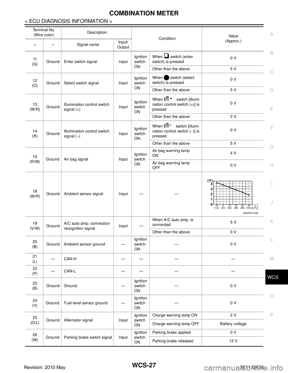
11
(G) Ground Enter switch signal Input Ignition
switch
ONWhen switch (enter
switch) is pressed
0 V
Other than the above 5 V
12
(O) Ground Select switch signal Input Ignition
switch
ONWhen switch (select
switch) is pressed
0 V
Other than the above 5 V
13
(W/R) Ground
Illumination control switch
signal (+) InputIgnition
switch
ON When switch [illumi-
nation control switch (+)] is
pressed
0 V
Other than the above 5 V
14
(R) Ground Illumination control switch
signal (
−) InputIgnition
switch
ON When switch [illumi-
nation control switch (
−)] is
pressed 0 V
Other than the above 5 V
15
(R/W) Ground Air bag signal Input Ignition
switch
ONAir bag warning lamp
ON
4 V
Air bag warning lamp
OFF 0 V
18
(W/R) Ground Ambient sensor signal Input — —
19
(V/W) Ground A/C auto amp. connection
recognition signal Input —When A/C auto amp. is
connected
5 V
Other than the above 0 V
20
(B) Ground Ambient sensor ground — Ignition
switch
ON—0 V
21
(L) —CAN-H — — — —
22
(P) —CAN-L — — — —
23
(B) Ground Ground — Ignition
switch
ON
—0 V
24
(V) Ground Fuel level sensor ground — Ignition
switch
ON—0 V
25
(O/L) Ground Alternator signal Input Ignition
switch
ONCharge warning lamp ON 2 V
Charge warning lamp OFF Battery voltage
26
(W) Ground Parking brake switch signal Input Ignition
switch
ONParking brake applied 0 V
Parking brake released 12 V
Te r m i n a l N o .
(Wire color) Description
ConditionVa l u e
(Approx.)
+ – Signal name Input/
Output
JSNIA0014GB
Revision: 2010 May2011 QX56
Page 5434 of 5598

WCS-30
< ECU DIAGNOSIS INFORMATION >
COMBINATION METER
DTC Index
INFOID:0000000006222690
Warning lamp/indicator lamp ABS warning lamp
The lamp turns ON by suspending communication.
VDC warning lamp
Brake warning lamp
IBA OFF indicator lamp
4WD warning lamp
Malfunction indicator lamp
VDC OFF indicator lamp
CRUISE warning lamp
Low tire pressure warning lamp The lamp blinking caused by suspending communication.
High beam indicator lamp
The lamp turns OFF by suspending communication.
Turn signal indicator lamp
Tail lamp indicator lamp
A/T CHECK indicator lamp
Key warning lamp
ATP warning lamp
Lane departure warning lamp
LDP ON indicator lamp
CRUISE indicator lamp
Oil pressure warning lamp
SNOW mode indicator lamp
TOW mode indicator lamp
CK SUSP indicator lamp
BSW indicator lamp
Function Specifications
Display contents of CONSULT-III Diagnostic item is detected when... Refer to
CAN COMM CIRCUIT
[U1000] When combination meter is not transmitting or receiving CAN communication signal
for 2 seconds or more. MWI-59,
"Diagnosis
Procedure"
CONTROL UNIT (CAN)
[U1010]
When detecting error during the initial diagnosis of the CAN controller of combina-
tion meter. MWI-60, "Diagnosis
Procedure"
VEHICLE SPEED
[B2205]
The abnormal vehicle sp
eed signal is input from the ABS actuator and electric unit
(control unit) for 2 seconds or more. MWI-61, "Diagnosis
Procedure"
ENGINE SPEED
[B2267]
If ECM continuously transmits abnormal engine speed signals for 2 seconds or
more. MWI-62, "Diagnosis
Procedure"
WATER TEMP
[B2268]
If ECM continuously transmits abnormal engine coolant temperature signals for 60
seconds or more. MWI-63, "Diagnosis
Procedure"
Revision: 2010 May2011 QX56
Page 5447 of 5598
WCS
PARKING BRAKE SWITCH SIGNAL CIRCUITWCS-43
< DTC/CIRCUIT DIAGNOSIS >
C
DE
F
G H
I
J
K L
M B A
O P
PARKING BRAKE SWITCH SIGNAL CIRCUIT
Diagnosis ProcedureINFOID:0000000006222530
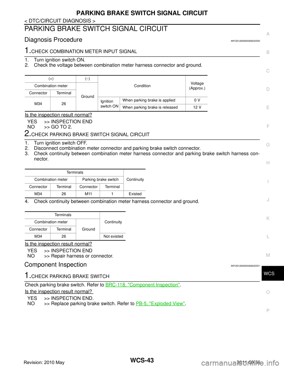
1.CHECK COMBINATION METER INPUT SIGNAL
1. Turn ignition switch ON.
2. Check the voltage between combination meter harness connector and ground.
Is the inspection result normal?
YES >> INSPECTION END
NO >> GO TO 2.
2.CHECK PARKING BRAKE SWITCH SIGNAL CIRCUIT
1. Turn ignition switch OFF.
2. Disconnect combination meter connecto r and parking brake switch connector.
3. Check continuity between combination meter har ness connector and parking brake switch harness con-
nector.
4. Check continuity between combination meter harness connector and ground.
Is the inspection result normal?
YES >> INSPECTION END
NO >> Repair harness or connector.
Component InspectionINFOID:0000000006222531
1.CHECK PARKING BRAKE SWITCH
Check parking brake switch. Refer to BRC-118, "
Component Inspection".
Is the inspection result normal?
YES >> INSPECTION END.
NO >> Replace parking brake switch. Refer to PB-5, "
Exploded View".
(+) (−)
Condition Vo l ta g e
(Approx.)
Combination meter
Ground
Connector Terminal
M34 26 Ignition
switch ONWhen parking brake is applied 0 V
When parking brake is released 12 V
Te r m i n a l s
Continuity
Combination meter Parking brake switch
Connector Terminal Connector Terminal M34 26 M11 1 Existed
Te r m i n a l s Continuity
Combination meter
Ground
Connector Terminal
M34 26 Not existed
Revision: 2010 May2011 QX56
Page 5450 of 5598
WCS-46
< SYMPTOM DIAGNOSIS >
THE PARKING BRAKE RELEASE WARNING CONTINUES SOUNDING, OR
DOES NOT SOUND
THE PARKING BRAKE RELEASE WARNING CONTINUES SOUNDING, OR
DOES NOT SOUND
DescriptionINFOID:0000000006222534
The parking brake warning buzzer sounds continuously during vehicle travel though the parking brake is
released.
The parking brake warning buzzer does not sound at a ll even though driving the vehicle with the parking
brake applied.
Diagnosis ProcedureINFOID:0000000006222535
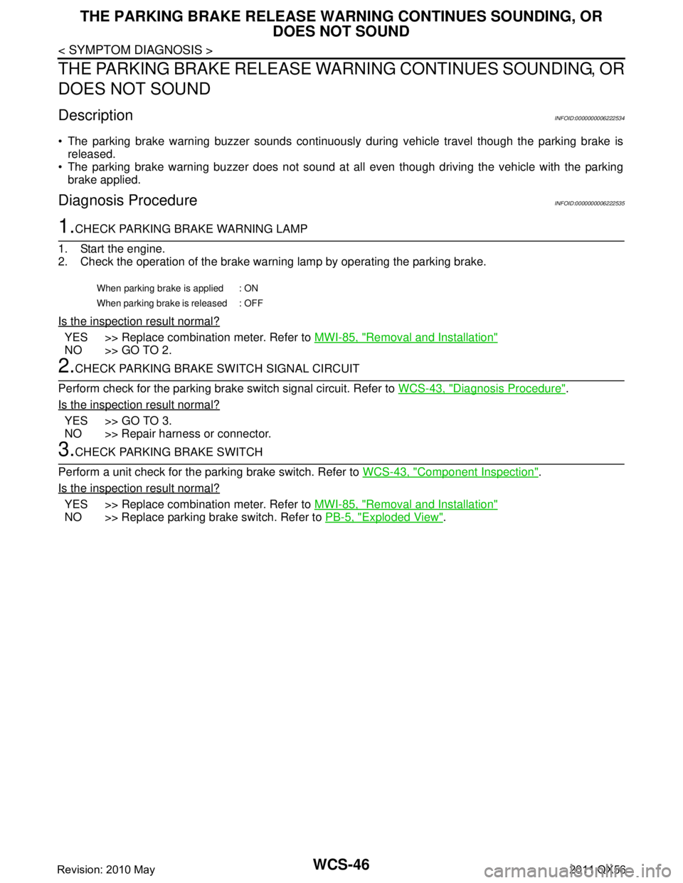
1.CHECK PARKING BRAKE WARNING LAMP
1. Start the engine.
2. Check the operation of the brake warni ng lamp by operating the parking brake.
Is the inspection result normal?
YES >> Replace combination meter. Refer to MWI-85, "Removal and Installation"
NO >> GO TO 2.
2.CHECK PARKING BRAKE SWITCH SIGNAL CIRCUIT
Perform check for the parking brake switch signal circuit. Refer to WCS-43, "
Diagnosis Procedure".
Is the inspection result normal?
YES >> GO TO 3.
NO >> Repair harness or connector.
3.CHECK PARKING BRAKE SWITCH
Perform a unit check for the parking brake switch. Refer to WCS-43, "
Component Inspection".
Is the inspection result normal?
YES >> Replace combination meter. Refer to MWI-85, "Removal and Installation"
NO >> Replace parking brake switch. Refer to PB-5, "Exploded View".
When parking brake is applied : ON
When parking brake is released : OFF
Revision: 2010 May2011 QX56
Page 5454 of 5598

WT-4
< PRECAUTION >
PRECAUTIONS
5. When the repair work is completed, re-connect both battery cables. With the brake pedal released, turn
the push-button ignition switch from ACC position to ON position, then to LOCK position. (The steering
wheel will lock when the push-button igniti on switch is turned to LOCK position.)
6. Perform self-diagnosis check of all control units using CONSULT-III.
Service Notice or Precautions for TPMSINFOID:0000000006225485
Low tire pressure warning lamp blinks for 1min, then turns ON when occurring any malfunction except low tire pressure. Erase the self-diagnosis memories for low tire pressure warning control unit, or register the ID
to turn low tire pressure warning lamp OFF. For ID registration, refer to WT-29, "
Work Procedure".
ID registration is required when replacing or rotating wheel s, replacing transmitter or low tire pressure warn-
ing control unit. Refer to WT-29, "
Work Procedure".
Replace grommet seal, valve core and cap of transmitter in TPMS, when replacing each tire by reaching the
wear limit. Refer to WT-66, "
Exploded View".
For tire inflation indicator function, refer to the following.
- When inflating the tires, park the vehicle in the safe area and ensure the safety of the working area.
- Read and understand the tire inflation indicator function prior to use.
- Inflate the tires one at a time.
- If there is no response for approximately 15 seconds or mo re after inflating the tires, cancel the use of the
tire inflation indicator function or move the vehicle approximately 1 m (3.2 ft) backward or forward to try
again. The air filler pressure may be weak or out of service area.
- Despite the high-precision TPMS pressure sensor, an i ndicated value may differ from that of the pressure
gauge.
- Air pressure is measured rather high due to the rise in tire air temperature after driving.
- If TPMS is malfunctioning, the tire inflation indicator is unusable.
Service Notice or Precautions for Road WheelINFOID:0000000006225486
Genuine NISSAN aluminum wheel is designed for each type of vehicle. Use it on the specified vehicle only.
Use Genuine NISSAN parts for the wheel nuts.
Always use them after adjusting the wheel balance. For the balance weights, use Genuine NISSAN alumi-
num wheel weights.
Use caution when handling the aluminum wheels, because they can be easily scratched. When removing
dirt, do not use any abrasives, a wire brush, or other it ems that may scratch the coating. Use a neutral deter-
gent if a detergent is needed.
After driving on roads scattered with anti-ici ng salts, wash off the wheels completely.
When installing road wheels onto the vehicle, always wipe of f any dirt or foreign substances to prevent them
from being trapped between the contact surfaces of wheel.
Never apply oil to nut and bolt threads.
Revision: 2010 May2011 QX56
Page 5511 of 5598
NOISE, VIBRATION AND HARSHNESS (NVH) TROUBLESHOOTINGWT-61
< SYMPTOM DIAGNOSIS >
C
DF
G H
I
J
K L
M A
B
WT
N
O P
NOISE, VIBRATION AND HARSHN ESS (NVH) TROUBLESHOOTING
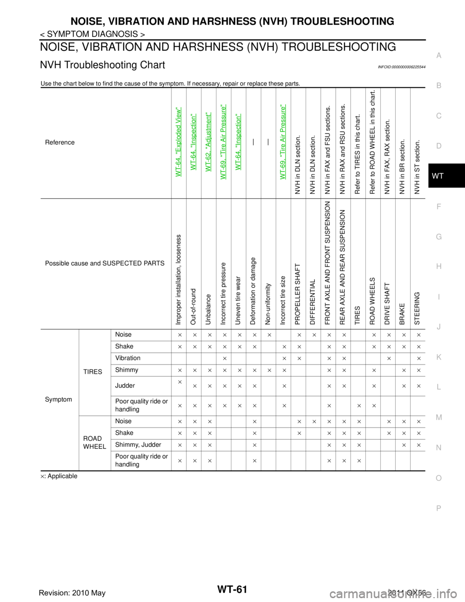
NVH Troubleshooting ChartINFOID:0000000006225544
Use the chart below to find the cause of the symp tom. If necessary, repair or replace these parts.
×: ApplicableReference
WT-64, "
Exploded View
"
WT-64, "
Inspection
"
WT-62, "
Adjustment
"
WT-69, "
Tire Air Pressure
"
WT-64, "
Inspection
"
—
—
WT-69, "
Tire Air Pressure
"
NVH in DLN section.
NVH in DLN section.
NVH in FAX and FSU sections.
NVH in RAX and RSU sections.
Refer to TIRES in this chart.
Refer to ROAD WHEEL in this chart.
NVH in FAX, RAX section.
NVH in BR section.
NVH in ST section.
Possible cause and SUSPECTED PARTS
Improper installation, looseness
Out-of-round
Unbalance
Incorrect tire pressure
Uneven tire wear
Deformation or damage
Non-uniformity
Incorrect tire size
PROPELLER SHAFT
DIFFERENTIAL
FRONT AXLE AND FRONT SUSPENSION
REAR AXLE AND REAR SUSPENSION
TIRES
ROAD WHEELS
DRIVE SHAFT
BRAKE
STEERING
Symptom TIRESNoise
××××××× ×××× ××××
Shake ×××××× ×× ×× ××××
Vibration ×××××××
Shimmy ×××××××× ×× × ××
Judder ×
××××× × ×× × ××
Poor quality ride or
handling ×××××× × × ××
ROAD
WHEEL Noise
××× × ××××× ×××
Shake ××× × × ××× ×××
Shimmy, Judder ××× × ××× ××
Poor quality ride or
handling ××× × ×××
Revision: 2010 May2011 QX56
Page 5523 of 5598
WW-4
< PRECAUTION >
PRECAUTIONS
5. When the repair work is completed, re-connect both battery cables. With the brake pedal released, turn
the push-button ignition switch from ACC position to ON position, then to LOCK position. (The steering
wheel will lock when the push-button igniti on switch is turned to LOCK position.)
6. Perform self-diagnosis check of all control units using CONSULT-III.
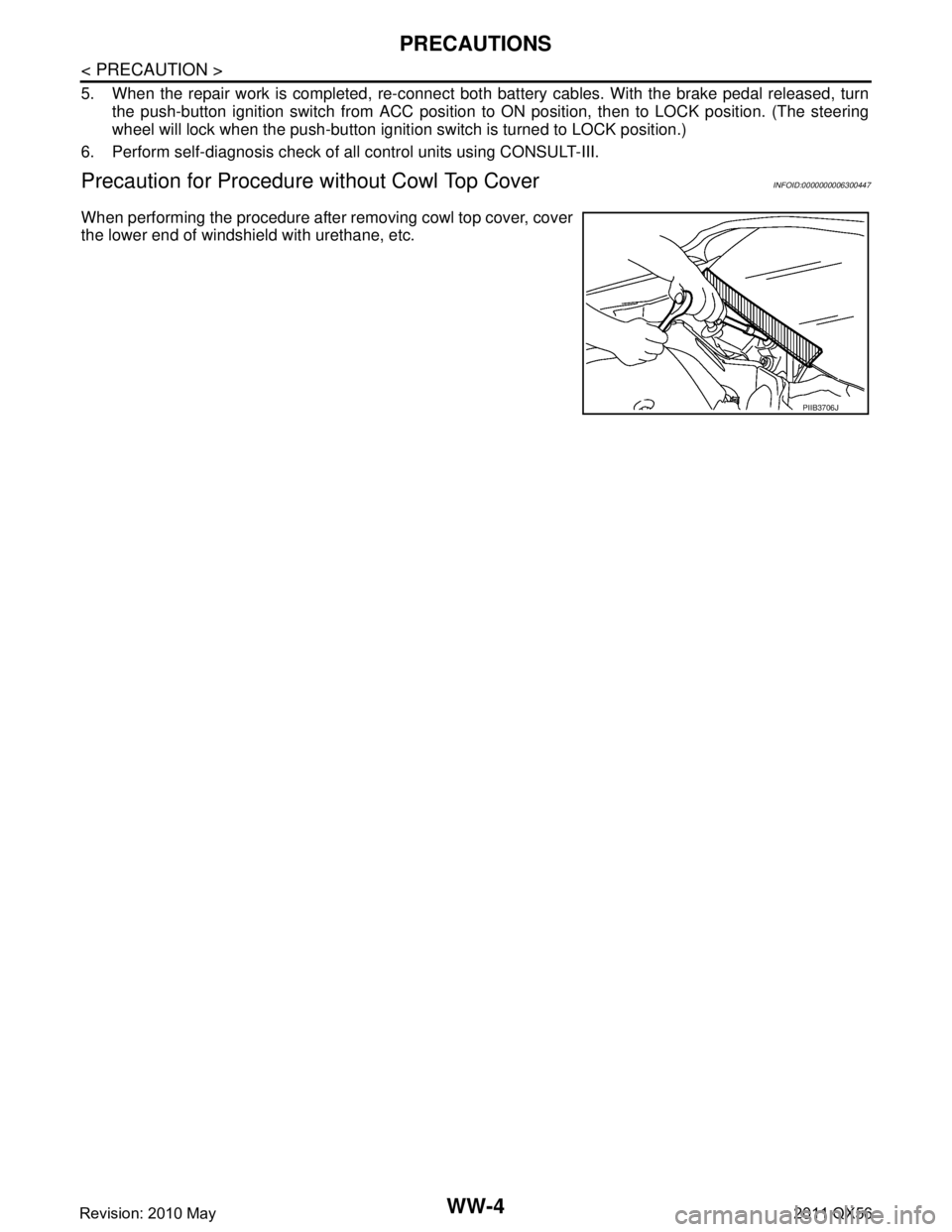
Precaution for Procedure without Cowl Top CoverINFOID:0000000006300447
When performing the procedure after removing cowl top cover, cover
the lower end of windshield with urethane, etc.
PIIB3706J
Revision: 2010 May2011 QX56