2011 INFINITI QX56 belt
[x] Cancel search: beltPage 2583 of 5598
DRIVE BELTSEM-21
< PERIODIC MAINTENANCE >
C
DE
F
G H
I
J
K L
M A
EM
NP
O
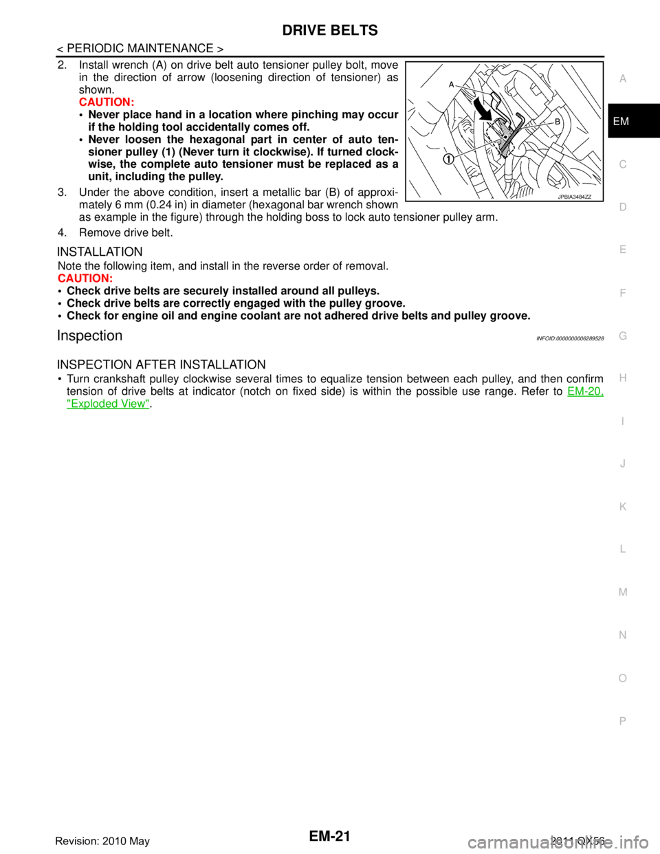
2. Install wrench (A) on drive belt auto tensioner pulley bolt, move
in the direction of arrow (loosening direction of tensioner) as
shown.
CAUTION:
Never place hand in a location where pinching may occurif the holding tool accidentally comes off.
Never loosen the hexagonal part in center of auto ten- sioner pulley (1) (Never turn it clockwise). If turned clock-
wise, the complete auto tensioner must be replaced as a
unit, including the pulley.
3. Under the above condition, insert a metallic bar (B) of approxi- mately 6 mm (0.24 in) in diameter (hexagonal bar wrench shown
as example in the figure) through the holding boss to lock auto tensioner pulley arm.
4. Remove drive belt.
INSTALLATION
Note the following item, and install in the reverse order of removal.
CAUTION:
Check drive belts are securely installed around all pulleys.
Check drive belts are correctly engaged with the pulley groove.
Check for engine oil and engine coolant ar e not adhered drive belts and pulley groove.
InspectionINFOID:0000000006289528
INSPECTION AFTER INSTALLATION
Turn crankshaft pulley clockwise several times to equalize tension between each pulley, and then confirm
tension of drive belts at indicator (notch on fixed side) is within the possible use range. Refer to EM-20,
"Exploded View".
JPBIA3484ZZ
Revision: 2010 May2011 QX56
Page 2588 of 5598
EM-26
< REMOVAL AND INSTALLATION >
DRIVE BELT AUTO TENSIONER AND IDLER PULLEY
DRIVE BELT AUTO TENSI ONER AND IDLER PULLEY
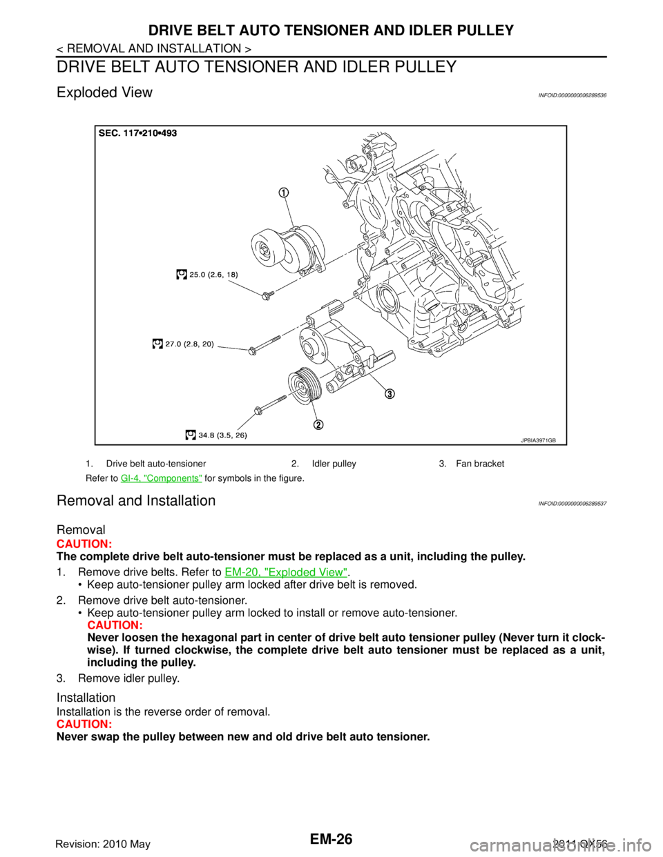
Exploded ViewINFOID:0000000006289536
Removal and InstallationINFOID:0000000006289537
Removal
CAUTION:
The complete drive belt auto-tensioner must be replaced as a unit, including the pulley.
1. Remove drive belts. Refer to EM-20, "
Exploded View".
Keep auto-tensioner pulley arm locked after drive belt is removed.
2. Remove drive belt auto-tensioner. Keep auto-tensioner pulley arm locked to install or remove auto-tensioner.CAUTION:
Never loosen the hexagonal part in center of dri ve belt auto tensioner pulley (Never turn it clock-
wise). If turned clockwise, the complete drive belt auto tensioner must be replaced as a unit,
including the pulley.
3. Remove idler pulley.
Installation
Installation is the reverse order of removal.
CAUTION:
Never swap the pulley between new an d old drive belt auto tensioner.
1. Drive belt auto-tensioner 2. Idler pulley 3. Fan bracket
Refer to GI-4, "
Components" for symbols in the figure.
JPBIA3971GB
Revision: 2010 May2011 QX56
Page 2593 of 5598
INTAKE MANIFOLDEM-31
< REMOVAL AND INSTALLATION >
C
DE
F
G H
I
J
K L
M A
EM
NP
O
Never spill engine coolant on drive belts.
NOTE:
When removing only intake manifold, move electric
throttle control actuator without disconnecting the
water hoses.
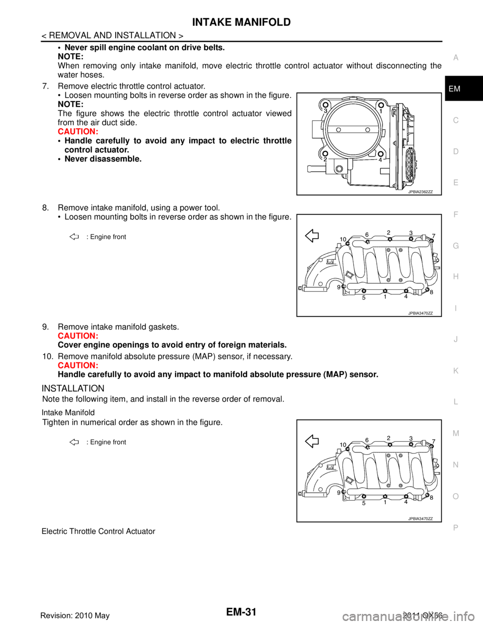
7. Remove electric throttle control actuator. Loosen mounting bolts in reverse order as shown in the figure.
NOTE:
The figure shows the electric throttle control actuator viewed
from the air duct side.
CAUTION:
Handle carefully to avoid an y impact to electric throttle
control actuator.
Never disassemble.
8. Remove intake manifold, using a power tool. Loosen mounting bolts in reverse order as shown in the figure.
9. Remove intake manifold gaskets. CAUTION:
Cover engine openings to avoid entry of foreign materials.
10. Remove manifold absolute pressure (MAP) sensor, if necessary. CAUTION:
Handle carefully to avoid any impact to manifold absolute pressure (MAP) sensor.
INSTALLATION
Note the following item, and install in the reverse order of removal.
Intake Manifold
Tighten in numerical order as shown in the figure.
Electric Throttle Control Actuator
JPBIA2362ZZ
: Engine front
JPBIA3470ZZ
: Engine front
JPBIA3470ZZ
Revision: 2010 May2011 QX56
Page 2602 of 5598

EM-40
< REMOVAL AND INSTALLATION >
EXHAUST MANIFOLD AND THREE WAY CATALYST
EXHAUST MANIFOLD AND THREE WAY CATALYST
Exploded ViewINFOID:0000000006289550
Removal and InstallationINFOID:0000000006289551
REMOVAL
WARNING:
Perform the work when the exhaust and cooling system have cooled sufficiently.
1. Drain engine coolant from radiator. Refer to CO-8, "
Draining".
CAUTION:
Perform this step when the engine is cold.
Never spill engine coolant on drive belt.
2. Remove reservoir tank. Refer to CO-13, "
Exploded View".
3. Remove drive belt. Refer to EM-20, "
Removal and Installation".
4. Remove power steering oil pump. Refer to ST-48, "
Exploded View".
5. Remove radiator. Refer to CO-13, "
Exploded View".
6. Remove front under cover. Refer to EXT-25, "
Exploded View".
7. Remove front wheels and tires. Refer to WT-64, "
Exploded View".
8. Remove A/C compressor. Refer to HA-30, "
Exploded View".
9. Remove alternator and alternator bracket. Refer to CHG-25, "
Exploded View".
10. Remove exhaust front tube (bank 1 and bank 2). Refer to EX-5, "
Exploded View".
1. Air fuel ratio sensor 1 (bank 2) 2. Exhaust manifold cover (bank 2) 3. Exhaust manifold and three way cat-
alyst (bank 2)
4. Gasket 5. Exhaust manifold and three way cat-
alyst (bank 1)6. Exhaust manifold cover (bank 1)
7. Air fuel ratio sensor 1 (bank 1)
Refer to GI-4, "
Components" for symbols in the figure.
JSBIA0389GB
Revision: 2010 May2011 QX56
Page 2624 of 5598
EM-62
< REMOVAL AND INSTALLATION >
TIMING CHAIN
Removal and Installation
INFOID:0000000006289566
REMOVAL
1. Release fuel pressure. Refer to EC-153, "Work Procedure".
2. Drain engine coolant from radiator. Refer to CO-8, "
Draining".
3. Remove fan shroud (lower). Refer to CO-13, "
Exploded View".
4. Remove fan bracket. Refer to CO-16, "
Exploded View".
5. Remove drive belt auto-tensioner. Refer to EM-26, "
Exploded View".
6. Remove oil level gauge and oil level gauge guide. Refer to EM-57, "
Exploded View".
7. Move power steering oil pump to the posit ion without the hindrance for work. Refer to ST-48, "
Exploded
View".
8. Remove alternator, alternator bracket and alternator stay. Refer to CHG-25, "
Exploded View".
9. Move power steering reservoir tank to the position without the hindrance for work, and then remove Res- ervoir tank bracket. Refer to ST-54, "
Exploded View".
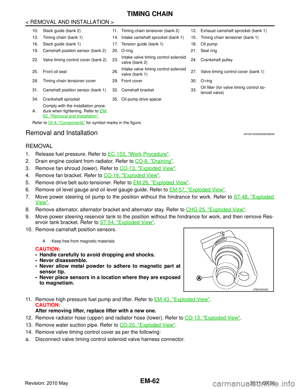
10. Remove camshaft position sensors.
CAUTION:
Handle carefully to avoid dropping and shocks.
Never disassemble.
Never allow metal powder to adhere to magnetic part atsensor tip.
Never place sensors in a lo cation where they are exposed
to magnetism.
11. Remove high pressure fuel pump and lifter. Refer to EM-43, "
Exploded View".
CAUTION:
After removing lifter, replace lifter with a new one.
12. Remove radiator hose (upper) and radiator hose (lower). Refer to CO-13, "
Exploded View".
13. Remove water suction pipe. Refer to CO-20, "
Exploded View".
14. Remove valve timing control cover as per the following:
a. Disconnect valve timing control solenoid valve harness connector.
10. Slack guide (bank 2) 11. Timing chain tensioner (bank 2) 12. Exhaust camshaft sprocket (bank 1)
13. Timing chain (bank 1) 14. Intake camshaft sprocket (bank 1) 15. Timing chain tensioner (bank 1)
16. Slack guide (bank 1) 17. Tension guide (bank 1) 18. Oil pump
19. Camshaft position sensor (bank 2) 20. O-ring 21. Seal ring
22. Valve timing control cover (bank 2) 23. Intake valve timing control solenoid
valve (bank 2)24. Crankshaft pulley
25. Front oil seal 26. Intake valve timing control solenoid
valve (bank 1)27. Valve timing control cover (bank 1)
28. Timing chain tensioner cover 29. Front cover 30. O-ring
31. Camshaft position sensor (bank 1) 32. Camshaft bracket 33. Oil filter (for valve timing control so-
lenoid valve)
34. Crankshaft sprocket 35. Oil pump drive spacer
A. Comply with the installation proce-
dure when tightening. Refer to
EM-
62, "Removal and Installation".
Refer to GI-4, "
Components" for symbol marks in the figure.
A : Keep free from magnetic materials
JPBIA0454ZZ
Revision: 2010 May2011 QX56
Page 2634 of 5598
EM-72
< REMOVAL AND INSTALLATION >
TIMING CHAIN
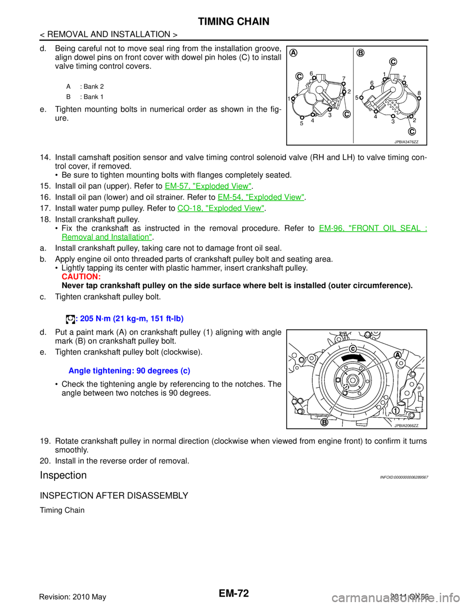
d. Being careful not to move seal ring from the installation groove,align dowel pins on front cover with dowel pin holes (C) to install
valve timing control covers.
e. Tighten mounting bolts in numerical order as shown in the fig- ure.
14. Install camshaft position sensor and valve timing c ontrol solenoid valve (RH and LH) to valve timing con-
trol cover, if removed.
Be sure to tighten mounting bolts with flanges completely seated.
15. Install oil pan (upper). Refer to EM-57, "
Exploded View".
16. Install oil pan (lower) and oil strainer. Refer to EM-54, "
Exploded View".
17. Install water pump pulley. Refer to CO-18, "
Exploded View".
18. Install crankshaft pulley. Fix the crankshaft as instructed in the removal procedure. Refer to EM-96, "
FRONT OIL SEAL :
Removal and Installation".
a. Install crankshaft pulley, taking care not to damage front oil seal.
b. Apply engine oil onto threaded parts of crankshaft pulley bolt and seating area. Lightly tapping its center with plastic hammer, insert crankshaft pulley.
CAUTION:
Never tap crankshaft pulley on the side surface wh ere belt is installed (outer circumference).
c. Tighten crankshaft pulley bolt.
d. Put a paint mark (A) on crankshaft pulley (1) aligning with angle mark (B) on crankshaft pulley bolt.
e. Tighten crankshaft pulley bolt (clockwise).
Check the tightening angle by referencing to the notches. Theangle between two notches is 90 degrees.
19. Rotate crankshaft pulley in normal direction (clockwise when viewed from engine front) to confirm it turns smoothly.
20. Install in the reverse order of removal.
InspectionINFOID:0000000006289567
INSPECTION AFTER DISASSEMBLY
Timing Chain
A: Bank 2
B: Bank 1
JPBIA3476ZZ
: 205 N·m (21 kg-m, 151 ft-lb)
Angle tightening: 90 degrees (c)
JPBIA2066ZZ
Revision: 2010 May2011 QX56
Page 2646 of 5598
EM-84
< REMOVAL AND INSTALLATION >
CAMSHAFT
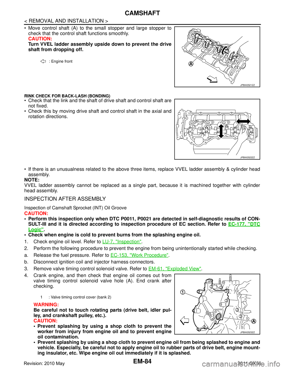
Move control shaft (A) to the small stopper and large stopper tocheck that the control shaft functions smoothly.
CAUTION:
Turn VVEL ladder assembly upside down to prevent the drive
shaft from dropping off.
RINK CHECK FOR BACK-LASH (BONDING) Check that the link and the shaft of drive shaft and control shaft are
not fixed.
Check this by moving drive shaft and control shaft in the axial and
rotation directions.
If there is an unusualness related to the above three items, replace VVEL ladder assembly & cylinder head
assembly.
NOTE:
VVEL ladder assembly cannot be replaced as a singl e part, because it is machined together with cylinder
head assembly.
INSPECTION AFTER ASSEMBLY
Inspection of Camshaft Sprocket (INT) Oil Groove
CAUTION:
Perform this inspection only when DTC P0011, P 0021 are detected in self-diagnostic results of CON-
SULT-III and it is directed according to inspection procedure of EC section. Refer to EC-177, "
DTC
Logic".
Check when engine is cold to prevent burns from the splashing engine oil.
1. Check engine oil level. Refer to LU-7, "
Inspection".
2. Perform the following procedure to prevent the engine from being unintentionally started while checking.
a. Release the fuel pressure. Refer to EC-153, "
Work Procedure".
b. Disconnect ignition coil and injector harness connectors.
3. Remove valve timing control solenoid valve. Refer to EM-61, "
Exploded View".
4. Crank engine, and then check that engine oil comes out from valve timing control solenoid valve hole (A). End crank after
checking.
WARNING:
Be careful not to touch rotati ng parts (drive belt, idler pul-
ley, and crankshaft pulley, etc.).
CAUTION:
Prevent splashing by using a shop cloth to prevent the worker from injury from en gine oil and to prevent engine
oil contamination.
Prevent splashing by using a shop cloth to prevent engine oil from being splashed to engine and
vehicle. Especially, be careful not to apply engine oil to rubber parts of drive belt, engine mount-
ing insulator, etc. Wipe engine oil out immediately if it is splashed.
: Engine front
JPBIA3521ZZ
JPBIA3522ZZ
1 : Valve timing control cover (bank 2)
JPBIA3523ZZ
Revision: 2010 May2011 QX56
Page 2658 of 5598
EM-96
< REMOVAL AND INSTALLATION >
OIL SEAL
OIL SEAL
FRONT OIL SEAL
FRONT OIL SEAL : Removal and InstallationINFOID:0000000006289574
REMOVAL
1. Remove the following parts:
Front under cover, using a power tool. Refer to EXT-25, "
Exploded View".
Drive belt: Refer to EM-20, "
Exploded View".
Cooling fan: Refer to CO-16, "
Exploded View".
2. Remove crankshaft pulley as per the following:
a. Remove rear plate cover. Refer to EM-54, "
Exploded View".
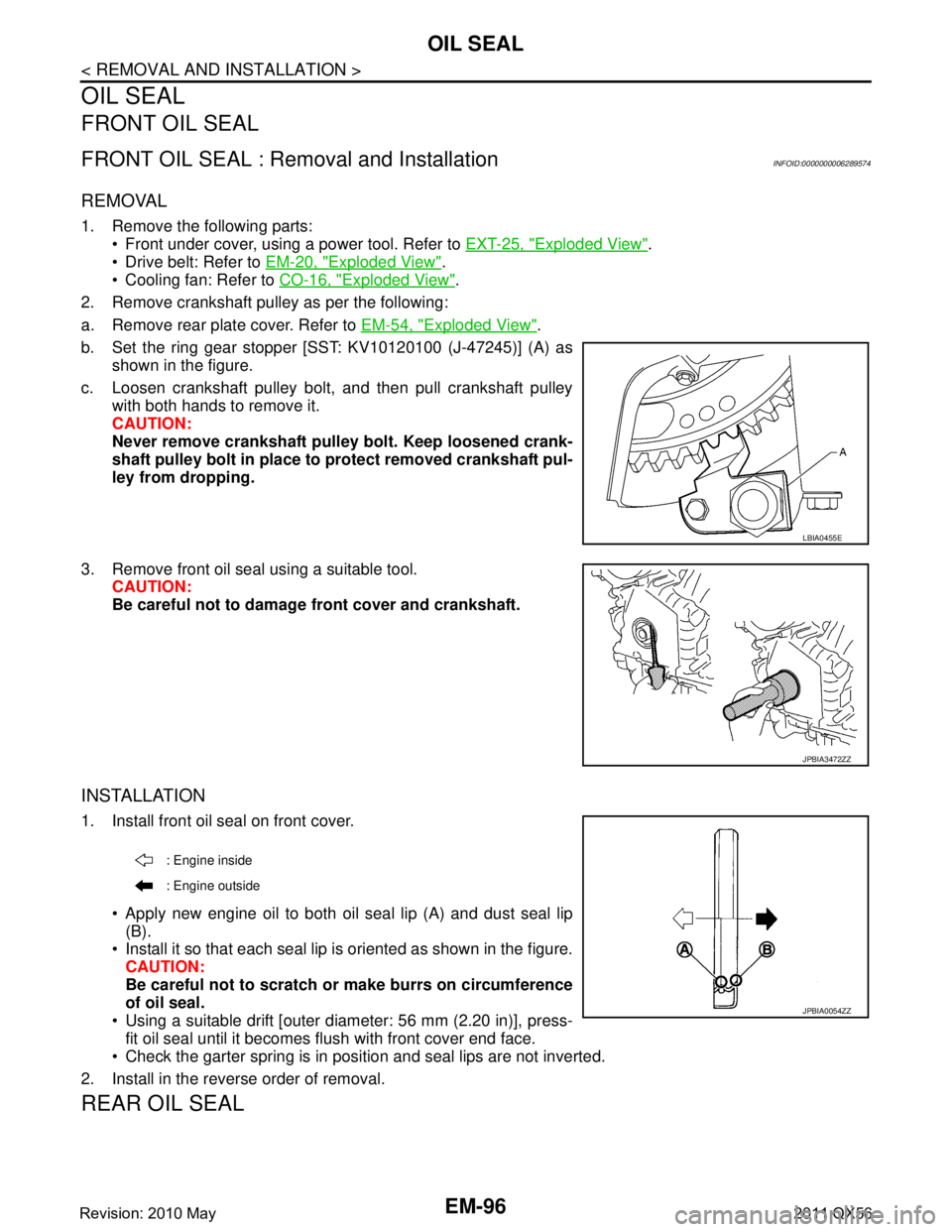
b. Set the ring gear stopper [SST: KV10120100 (J-47245)] (A) as shown in the figure.
c. Loosen crankshaft pulley bolt, and then pull crankshaft pulley with both hands to remove it.
CAUTION:
Never remove crankshaft pulley bolt. Keep loosened crank-
shaft pulley bolt in place to protect removed crankshaft pul-
ley from dropping.
3. Remove front oil seal using a suitable tool. CAUTION:
Be careful not to damage front cover and crankshaft.
INSTALLATION
1. Install front oil seal on front cover.
Apply new engine oil to both oil seal lip (A) and dust seal lip(B).
Install it so that each seal lip is oriented as shown in the figure. CAUTION:
Be careful not to scratch or make burrs on circumference
of oil seal.
Using a suitable drift [outer diameter: 56 mm (2.20 in)], press- fit oil seal until it becomes flush with front cover end face.
Check the garter spring is in position and seal lips are not inverted.
2. Install in the reverse order of removal.
REAR OIL SEAL
LBIA0455E
JPBIA3472ZZ
: Engine inside
: Engine outside
JPBIA0054ZZ
Revision: 2010 May2011 QX56