2011 INFINITI QX56 belt
[x] Cancel search: beltPage 3031 of 5598
GW-2
< PRECAUTION >
PRECAUTIONS
PRECAUTION
PRECAUTIONS
Precaution for Supplemental Restraint System (SRS) "AIR BAG" and "SEAT BELT
PRE-TENSIONER"
INFOID:0000000006257243
The Supplemental Restraint System such as “A IR BAG” and “SEAT BELT PRE-TENSIONER”, used along
with a front seat belt, helps to reduce the risk or severi ty of injury to the driver and front passenger for certain
types of collision. This system includes seat belt switch inputs and dual stage front air bag modules. The SRS
system uses the seat belt switches to determine the front air bag deployment, and may only deploy one front
air bag, depending on the severity of a collision and w hether the front occupants are belted or unbelted.
Information necessary to service the system safely is included in the “SRS AIR BAG” and “SEAT BELT” of this
Service Manual.
WARNING:
• To avoid rendering the SRS inopera tive, which could increase the risk of personal injury or death in
the event of a collision that would result in air bag inflation, all maintenance must be performed by
an authorized NISS AN/INFINITI dealer.
Improper maintenance, including in correct removal and installation of the SRS, can lead to personal
injury caused by unintent ional activation of the system. For re moval of Spiral Cable and Air Bag
Module, see the “SRS AIR BAG”.
Do not use electrical test equipmen t on any circuit related to the SRS unless instructed to in this
Service Manual. SRS wiring harnesses can be identi fied by yellow and/or orange harnesses or har-
ness connectors.
PRECAUTIONS WHEN USING POWER TOOLS (AIR OR ELECTRIC) AND HAMMERS
WARNING:
When working near the Air Bag Diagnosis Sensor Unit or other Air Bag System sensors with the ignition ON or engine running, DO NOT use air or electric power tools or strike near the sensor(s)
with a hammer. Heavy vibration could activate the sensor(s) and deploy the air bag(s), possibly
causing serious injury.
When using air or electric power tools or hammers , always switch the ignition OFF, disconnect the
battery, and wait at least 3 minu tes before performing any service.
Precaution Necessary for Steering W heel Rotation after Battery Disconnect
INFOID:0000000006257244
NOTE:
Before removing and installing any control units, first tu rn the push-button ignition switch to the LOCK posi-
tion, then disconnect bot h battery cables.
After finishing work, confirm that all control unit connectors are connected properly, then re-connect both
battery cables.
Always use CONSULT-III to perform self-diagnosis as a part of each function inspection after finishing work.
If a DTC is detected, perform trouble diagnos is according to self-diagnosis results.
For vehicle with steering lock unit, if the battery is disconnected or discharged, the steering wheel will lock and
cannot be turned.
If turning the steering wheel is required with the bat tery disconnected or discharged, follow the operation pro-
cedure below before starting the repair operation.
OPERATION PROCEDURE
1. Connect both battery cables. NOTE:
Supply power using jumper cables if battery is discharged.
2. Turn the push-button ignition switch to ACC position. (At this time, the steering lock will be released.)
3. Disconnect both battery cables. The steering lock wi ll remain released with both battery cables discon-
nected and the steering wheel can be turned.
4. Perform the necessary repair operation.
Revision: 2010 May2011 QX56
Page 3057 of 5598

HA-1
VENTILATION, HEATER & AIR CONDITIONER
C
DE
F
G H
J
K L
M
SECTION HA
A
B
HA
N
O P
CONTENTS
HEATER & AIR CONDITIONING SYSTEM
PRECAUTION ................ ...............................3
PRECAUTIONS .............................................. .....3
Precaution for Supplemental Restraint System
(SRS) "AIR BAG" and "SEAT BELT PRE-TEN-
SIONER" ............................................................. ......
3
Precaution Necessary for Steering Wheel Rota-
tion after Battery Disconnect .....................................
3
Precaution for Procedure without Cowl Top Cover ......4
Precautions For Refrigerant System Service ............4
Service Equipment ....................................................6
PREPARATION ............................................9
PREPARATION .............................................. .....9
Special Service Tool ........................................... ......9
Commercial Service Tool ........................................12
Sealant or/and Lubricant .........................................12
SYSTEM DESCRIPTION .............................13
COMPONENT PARTS ................................... ....13
Component Parts Location .................................. ....13
Component Description ...........................................13
SYSTEM .............................................................14
System Diagram .................................................. ....14
System Description .................................................14
BASIC INSPECTION ...................................16
DIAGNOSIS AND REPAIR WORKFLOW ..... ....16
Work Flow ........................................................... ....16
REFRIGERANT ..................................................18
Description .......................................................... ....18
Leak Test ................................................................18
Recycle Refrigerant .................................................20
Charge Refrigerant ..................................................20
LUBRICANT ................................................... ....22
Description .......................................................... ....22
Inspection ............................................................ ....22
Perform Lubricant Return Operation .......................22
Lubricant Adjusting Procedure for Components
Replacement Except Compressor ...........................
22
Lubricant Adjusting Procedure for Compressor
Replacement ...........................................................
23
PERFORMANCE TEST ....................................25
Inspection ................................................................25
SYMPTOM DIAGNOSIS ..............................27
REFRIGERATION SYSTEM SYMPTOMS ........27
Trouble Diagnosis For Unusual Pressure ............ ....27
Symptom Table .......................................................27
NOISE ................................................................29
Symptom Table .......................................................29
REMOVAL AND INSTALLATION ...............30
COMPRESSOR .................................................30
Exploded View ..................................................... ....30
COMPRESSOR ..........................................................30
COMPRESSOR : Removal and Installation ............30
MAGNET CLUTCH ................................................ ....31
MAGNET CLUTCH : Removal and Installation of
Compressor Clutch ..................................................
31
Inspection ................................................................32
COOLER PIPE AND HOSE ..............................33
Exploded View .........................................................33
HIGH-PRESSURE FLEXIBLE HOSE ........................34
HIGH-PRESSURE FLEXIBLE HOSE : Removal
and Installation .................................................... ....
34
LOW-PRESSURE FLEXIBLE HOSE ..................... ....35
LOW-PRESSURE FLEXIBLE HOSE : Removal
and Installation ........................................................
35
HIGH-PRESSURE PIPE ............................................35
Revision: 2010 May2011 QX56
Page 3058 of 5598

HA-2
HIGH-PRESSURE PIPE : Removal and Installa-
tion ....................................................................... ...
35
LOW-PRESSURE PIPE ......................................... ...36
LOW-PRESSURE PIPE : Removal and Installa-
tion ..........................................................................
36
REAR COOLER PIPE ............................................ ...37
REAR COOLER PIPE : Removal and Installation ...37
CONDENSER ................................................. ...38
Exploded View ..................................................... ...38
CONDENSER ......................................................... ...38
CONDENSER : Removal and Installation ..............38
LIQUID TANK ......................................................... ...39
LIQUID TANK : Removal and Installation ...............39
REFRIGERANT PRESSURE SENSOR ....................39
REFRIGERANT PRESSURE SENSOR : Remov-
al and Installation ................................................. ...
39
A/C UNIT ASSEMBLY .................................... ...41
Exploded View ..................................................... ...41
HEATER & COOLING UNIT ASSEMBLY ................42
HEATER & COOLING UNIT ASSEMBLY : Re-
moval and Installation .......................................... ...
42
EVAPORATOR ...................................................... ...43
EVAPORATOR : Removal and Installation ............43
HEATER CORE ...................................................... ...44
HEATER CORE : Removal and Installation ...........44
EXPANSION VALVE .............................................. ...44
EXPANSION VALVE : Removal and Installation ....44
REAR A/C UNIT ................................................46
Exploded View ..................................................... ...46
REAR A/C UNIT ASSEMBLY ...................................47
REAR A/C UNIT ASSEMBLY : Removal and In-
stallation ............................................................... ...
47
EVAPORATOR ....................................................... ...48
EVAPORATOR : Removal and Installation .............48
EVAPORATOR PIPE ASSEMBLY ........................ ...48
EVAPORATOR PIPE ASSEMBLY : Removal and
Installation ...............................................................
48
HEATER CORE ...................................................... ...48
HEATER CORE : Removal and Installation ............48
EXPANSION VALVE .............................................. ...49
EXPANSION VALVE : Removal and Installation ....49
SERVICE DATA AND SPECIFICATIONS
(SDS) .......... ................................................
50
SERVICE DATA AND SPECIFICATIONS
(SDS) .............................................................. ...
50
Compressor ......................................................... ...50
Lubricant .................................................................50
Refrigerant ..............................................................50
Engine Idling Speed ................................................50
Belt Tension ............................................................50
Revision: 2010 May2011 QX56
Page 3059 of 5598
PRECAUTIONSHA-3
< PRECAUTION >
C
DE
F
G H
J
K L
M A
B
HA
N
O P
PRECAUTION
PRECAUTIONS
Precaution for Supplemental Restraint System (SRS) "AIR BAG" and "SEAT BELT
PRE-TENSIONER"
INFOID:0000000006276136
The Supplemental Restraint System such as “A IR BAG” and “SEAT BELT PRE-TENSIONER”, used along
with a front seat belt, helps to reduce the risk or severi ty of injury to the driver and front passenger for certain
types of collision. This system includes seat belt switch inputs and dual stage front air bag modules. The SRS
system uses the seat belt switches to determine the front air bag deployment, and may only deploy one front
air bag, depending on the severity of a collision and whether the front occupants are belted or unbelted.
Information necessary to service the system safely is included in the “SRS AIR BAG” and “SEAT BELT” of this
Service Manual.
WARNING:
• To avoid rendering the SRS inoper ative, which could increase the risk of personal injury or death in
the event of a collision that would result in air ba g inflation, all maintenance must be performed by
an authorized NISSAN/INFINITI dealer.
Improper maintenance, including in correct removal and installation of the SRS, can lead to personal
injury caused by unintentional act ivation of the system. For removal of Spiral Cable and Air Bag
Module, see the “SRS AIR BAG”.
Do not use electrical test equipm ent on any circuit related to the SRS unless instructed to in this
Service Manual. SRS wiring harnesses can be identi fied by yellow and/or orange harnesses or har-
ness connectors.
PRECAUTIONS WHEN USING POWER TOOLS (AIR OR ELECTRIC) AND HAMMERS
WARNING:
When working near the Air Bag Diagnosis Sensor Unit or other Air Bag System sensors with the
ignition ON or engine running, DO NOT use air or electric power tools or strike near the sensor(s)
with a hammer. Heavy vibration could activate the sensor(s) and deploy the air bag(s), possibly
causing serious injury.
When using air or electric power tools or hammers , always switch the ignition OFF, disconnect the
battery, and wait at least 3 minutes before performing any service.
Precaution Necessary for Steering Wh eel Rotation after Battery Disconnect
INFOID:0000000006276137
NOTE:
Before removing and installing any control units, first tu rn the push-button ignition switch to the LOCK posi-
tion, then disconnect both battery cables.
After finishing work, confirm that all control unit connectors are connected properly, then re-connect both
battery cables.
Always use CONSULT-III to perform self-diagnosis as a part of each function inspection after finishing work.
If a DTC is detected, perform trouble diagnos is according to self-diagnosis results.
For vehicle with steering lock unit, if the battery is disconnected or discharged, the steering wheel will lock and
cannot be turned.
If turning the steering wheel is required with the batte ry disconnected or discharged, follow the operation pro-
cedure below before starting the repair operation.
OPERATION PROCEDURE
1. Connect both battery cables. NOTE:
Supply power using jumper cables if battery is discharged.
2. Turn the push-button ignition switch to ACC position. (At this time, the steering lock will be released.)
3. Disconnect both battery cables. The steering lock wil l remain released with both battery cables discon-
nected and the steering wheel can be turned.
4. Perform the necessary repair operation.
Revision: 2010 May2011 QX56
Page 3085 of 5598
NOISEHA-29
< SYMPTOM DIAGNOSIS >
C
DE
F
G H
J
K L
M A
B
HA
N
O P
NOISE
Symptom TableINFOID:0000000006276161
Symptom Noise source Probable cause Corrective action
Unusual noise from compressor
when A/C is ON. Inside of compressor
Wear, breakage, or clogging of foreign
material in inner parts. Check compressor oil. Re-
fer to
HA-22, "
Inspection".
Magnet clutch Contact of clutch disc with pulley. Check clearance between
clutch disc and pulley. Refer
to
HA-32, "
Inspection".
Compressor body Loosened compressor mounting bolts. Check bolts for tightness.
Refer to
HA-30, "
Exploded
View".
Unusual noise from cooler piping. Cooler piping (pipe and
flexible hose)Improper installation of clip and brack-
et. Check the installation condi-
tion of the cooler piping. Re-
fer to
HA-33, "
Exploded
View".
Unusual noise from expansion
valve when A/C is ON. Expansion valveShortage of refrigerant. Check for leakage.
Collect all refrigerant,
evacuate refrigerant cycle
again, and then refill it
with the specified amount
of refrigerant.
Wear, breakage, or clogging of foreign
material in inner parts. Eliminate foreign material
from expansion valve, or re-
place it.
Unusual noise from belt. — Loosened belt
Check belt tension. Refer to
EM-20, "
Checking".
Internal compressor parts ge t locked Replace compressor.
Revision: 2010 May2011 QX56
Page 3087 of 5598
COMPRESSORHA-31
< REMOVAL AND INSTALLATION >
C
DE
F
G H
J
K L
M A
B
HA
N
O P
Perform lubricant return operati on before each refrigeration system disassembly. However, if a large
amount of refrigerant or lubricant is detected, n ever perform lubricant return operation. Refer to HA-
22, "Perform Lubricant Return Operation".
REMOVAL
1. Use a refrigerant collecting equipment (for HF C-134a) to discharge the refrigerant. Refer to HA-20, "Recy-
cle Refrigerant".
2. Remove air cleaner. Refer to EM-27, "
Removal and Installation".
3. Remove mounting bolts, and then disconnect low-pressure flexible hose and high-pressure flexible hose from the compressor.
CAUTION:
Cap or wrap the joint of the A/C piping and comp ressor with suitable material such as vinyl tape to
avoid the entry of air.
4. Remove front under cover. Refer to EXT-25, "
Exploded View".
5. Remove drive belt. Refer to EM-20, "
Removal and Installation".
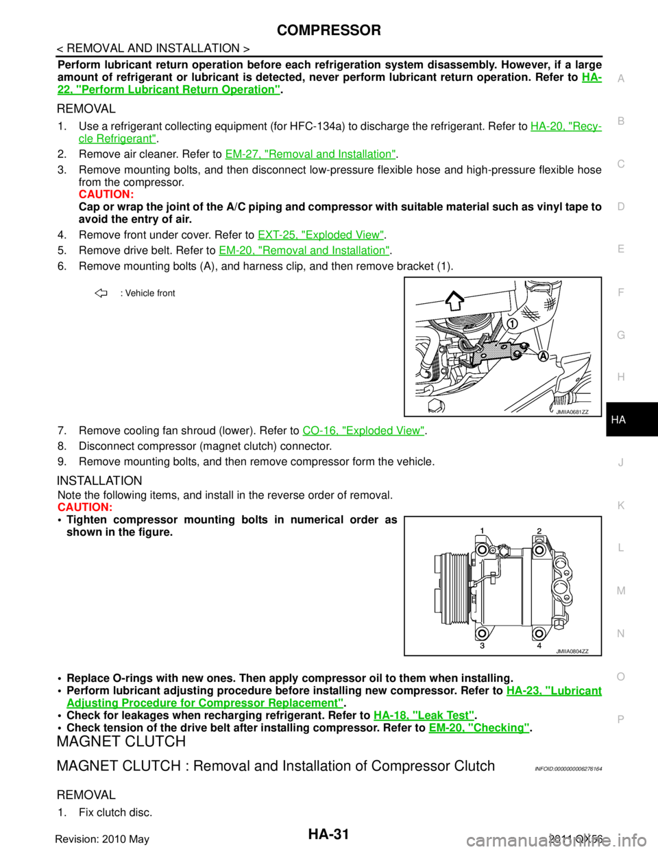
6. Remove mounting bolts (A), and harness clip, and then remove bracket (1).
7. Remove cooling fan shroud (lower). Refer to CO-16, "
Exploded View".
8. Disconnect compressor (magnet clutch) connector.
9. Remove mounting bolts, and then remove compressor form the vehicle.
INSTALLATION
Note the following items, and install in the reverse order of removal.
CAUTION:
Tighten compressor mounting bolts in numerical order as shown in the figure.
Replace O-rings with new ones. Then apply compressor oil to them when installing.
Perform lubricant adjusting procedure befo re installing new compressor. Refer to HA-23, "
Lubricant
Adjusting Procedure for Compressor Replacement".
Check for leakages when recharging refrigerant. Refer to HA-18, "
Leak Test".
Check tension of the drive belt afte r installing compressor. Refer to EM-20, "
Checking".
MAGNET CLUTCH
MAGNET CLUTCH : Removal and Inst allation of Compressor ClutchINFOID:0000000006276164
REMOVAL
1. Fix clutch disc.
: Vehicle front
JMIIA0681ZZ
JMIIA0804ZZ
Revision: 2010 May2011 QX56
Page 3106 of 5598
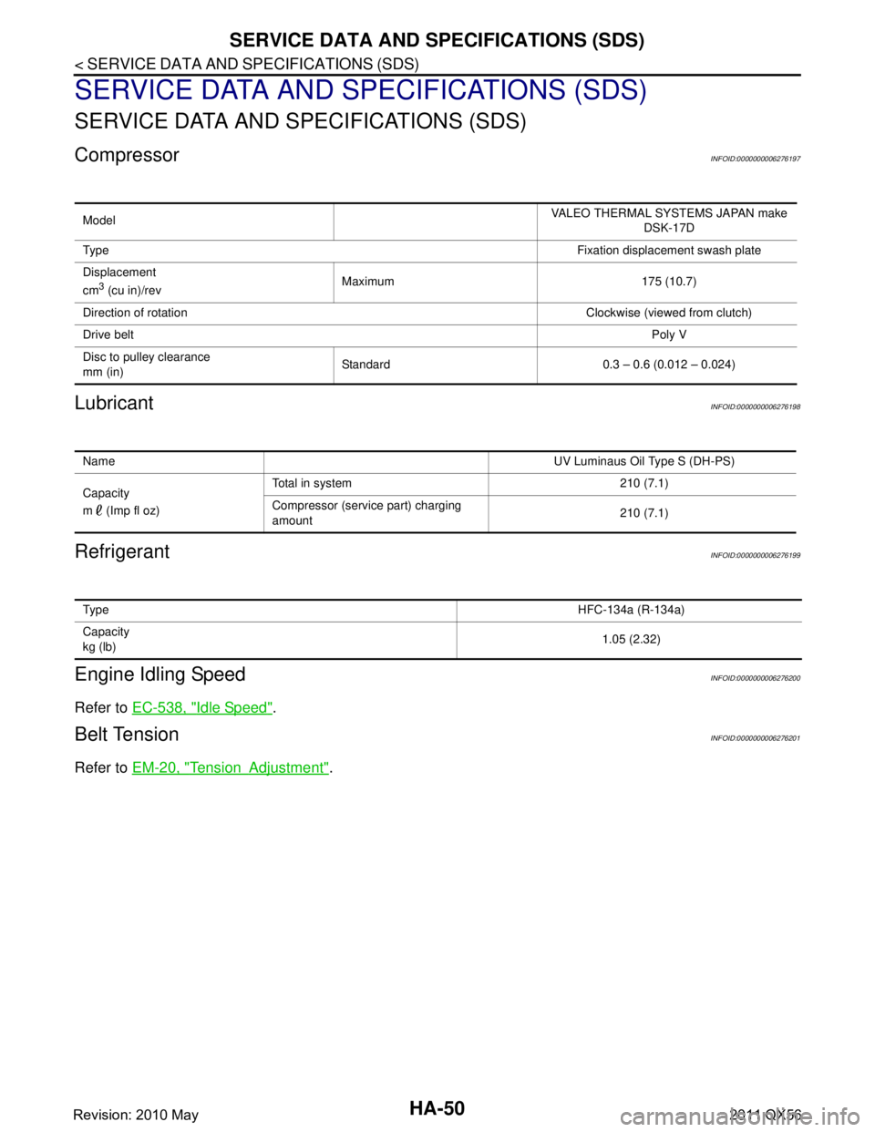
HA-50
< SERVICE DATA AND SPECIFICATIONS (SDS)
SERVICE DATA AND SPECIFICATIONS (SDS)
SERVICE DATA AND SPECIFICATIONS (SDS)
SERVICE DATA AND SPECIFICATIONS (SDS)
CompressorINFOID:0000000006276197
LubricantINFOID:0000000006276198
RefrigerantINFOID:0000000006276199
Engine Idling SpeedINFOID:0000000006276200
Refer to EC-538, "Idle Speed".
Belt TensionINFOID:0000000006276201
Refer to EM-20, "TensionAdjustment".
Model VALEO THERMAL SYSTEMS JAPAN make
DSK-17D
Ty p e Fixation displacement swash plate
Displacement
cm
3 (cu in)/rev Maximum 175 (10.7)
Direction of rotation Clockwise (viewed from clutch)
Drive belt Poly V
Disc to pulley clearance
mm (in) Standard 0.3 – 0.6 (0.012 – 0.024)
Name
UV Luminaus Oil Type S (DH-PS)
Capacity
m (Imp fl oz) Total in system 210 (7.1)
Compressor (service part) charging
amount
210 (7.1)
Ty p e
HFC-134a (R-134a)
Capacity
kg (lb) 1.05 (2.32)
Revision: 2010 May2011 QX56
Page 3107 of 5598

HAC-1
VENTILATION, HEATER & AIR CONDITIONER
C
DE
F
G H
J
K L
M
SECTION HAC
A
B
HAC
N
O P
CONTENTS
HEATER & AIR CONDITIONING CONTROL SYSTEM
AUTOMATIC AIR CONDITIONING
PRECAUTION ................ ...............................
5
PRECAUTIONS .............................................. .....5
Precaution for Supplemental Restraint System
(SRS) "AIR BAG" and "SEAT BELT PRE-TEN-
SIONER" ............................................................. ......
5
SYSTEM DESCRIPTION ..............................6
COMPONENT PARTS ................................... .....6
FRONT AUTOMATIC AIR CONDITIONING SYS-
TEM ........................................................................ ......
6
FRONT AUTOMATIC AIR CONDITIONING SYS-
TEM : Component Parts Location .............................
6
FRONT AUTOMATIC AIR CONDITIONING SYS-
TEM : Component Description ..................................
7
REAR AUTOMATIC AIR CONDITIONING SYS-
TEM ........................................................................ ......
8
REAR AUTOMATIC AIR CONDITIONING SYS-
TEM : Component Parts Location .............................
9
REAR AUTOMATIC AIR CONDITIONING SYS-
TEM : Component Description ................................
10
ACCS (ADVANCED CLIMATE CONTROL SYS-
TEM) ...................................................................... ....
10
ACCS (ADVANCED CLIMATE CONTROL SYS-
TEM) : Component Parts Location ..........................
11
ACCS (ADVANCED CLIMATE CONTROL SYS-
TEM) : Component Description ...............................
11
Aspirator ..................................................................12
Front Blower Motor ..................................................12
Rear Blower Motor ..................................................13
Refrigerant Pressure Sensor ...................................13
SYSTEM .............................................................14
FRONT AUTOMATIC AIR CONDITIONING SYS-
TEM ........................................................................ ....
14
FRONT AUTOMATIC AIR CONDITIONING SYS-
TEM : System Diagram ...........................................
14
FRONT AUTOMATIC AIR CONDITIONING SYS-
TEM : System Description .......................................
14
FRONT AUTOMATIC AIR CONDITIONING SYS-
TEM : Air Flow Control ............................................
15
FRONT AUTOMATIC AIR CONDITIONING SYS-
TEM : Air Inlet Control .............................................
16
FRONT AUTOMATIC AIR CONDITIONING SYS-
TEM : Air Outlet Control ..........................................
17
FRONT AUTOMATIC AIR CONDITIONING SYS-
TEM : Compressor Control ......................................
17
FRONT AUTOMATIC AIR CONDITIONING SYS-
TEM : Door Control ..................................................
18
FRONT AUTOMATIC AIR CONDITIONING SYS-
TEM : Temperature Control .....................................
21
FRONT AUTOMATIC AIR CONDITIONING SYS-
TEM : Fail-safe ........................................................
21
REAR AUTOMATIC AIR CONDITIONING SYS-
TEM ........................................................................ ....
22
REAR AUTOMATIC AIR CONDITIONING SYS-
TEM : System Diagram ...........................................
23
REAR AUTOMATIC AIR CONDITIONING SYS-
TEM : System Description .......................................
23
REAR AUTOMATIC AIR CONDITIONING SYS-
TEM : Air Flow Control ............................................
24
REAR AUTOMATIC AIR CONDITIONING SYS-
TEM : Air Outlet Control ..........................................
25
REAR AUTOMATIC AIR CONDITIONING SYS-
TEM : Door Control ..................................................
26
REAR AUTOMATIC AIR CONDITIONING SYS-
TEM : Temperature Control .....................................
27
ACCS (ADVANCED CLIMATE CONTROL SYS-
TEM) ....................................................................... ....
27
ACCS (ADVANCED CLIMATE CONTROL SYS-
TEM) : System Diagram ..........................................
28
ACCS (ADVANCED CLIMATE CONTROL SYS-
TEM) : System Description ......................................
28
Revision: 2010 May2011 QX56