Page 4363 of 5598

SCS-3
C
DF
G H
I
J
K L
M A
B
SCS
N
O P
N
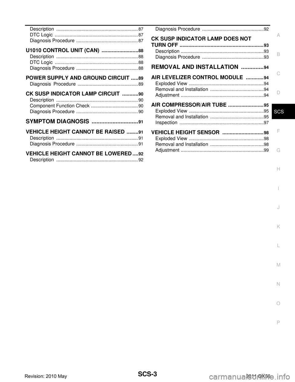
Description ..........................................................
....
87
DTC Logic ...............................................................87
Diagnosis Procedure ...............................................87
U1010 CONTROL UNIT (CAN) ..........................88
Description .......................................................... ....88
DTC Logic ...............................................................88
Diagnosis Procedure ...............................................88
POWER SUPPLY AND GROUND CIRCUIT ......89
Diagnosis Procedure .......................................... ....89
CK SUSP INDICATOR LAMP CIRCUIT ............90
Description .......................................................... ....90
Component Function Check ....................................90
Diagnosis Procedure ...............................................90
SYMPTOM DIAGNOSIS ..............................91
VEHICLE HEIGHT CANNOT BE RAISED ..... ....91
Description .......................................................... ....91
Diagnosis Procedure ...............................................91
VEHICLE HEIGHT CANNOT BE LOWERED ....92
Description ..............................................................92
Diagnosis Procedure ........................................... ....92
CK SUSP INDICATOR LAMP DOES NOT
TURN OFF ........................................ .................
93
Description ........................................................... ....93
Diagnosis Procedure ...............................................93
REMOVAL AND INSTALLATION ...............94
AIR LEVELIZER CONTROL MODULE ............94
Exploded View ..................................................... ....94
Removal and Installation .........................................94
Adjustment ...............................................................94
AIR COMPRESSOR/AIR TUBE ........................95
Exploded View .........................................................95
Removal and Installation .........................................95
Inspection ................................................................97
VEHICLE HEIGHT SENSOR ............................98
Exploded View .........................................................98
Removal and Installation .........................................98
Adjustment ...............................................................99
Revision: 2010 May2011 QX56
Page 4454 of 5598
SCS-94
< REMOVAL AND INSTALLATION >[AIR LEVELIZER CONTROL SYSTEM]
AIR LEVELIZER CONTROL MODULE
REMOVAL AND INSTALLATION
AIR LEVELIZER CONTROL MODULE
Exploded ViewINFOID:0000000006256098
Removal and InstallationINFOID:0000000006256099
REMOVAL
CAUTION:
Never impact on air levelizer contro
l module when removing or installing air levelizer control module.
1. Disconnect battery cable from negative terminal.
2. Remove luggage side lower finisher (LH). Refer to INT-33, "
Exploded View".
3. Disconnect air levelizer control module harness connector.
4. Remove the air levelizer control module.
INSTALLATION
Install in the reverse order of removal.
AdjustmentINFOID:0000000006256100
After air levelizer control module is replaced, perform “STANDARD VEHICLE HEIGHT SETTING”. Refer to
SCS-67, "
Work Procedure".
1. Air levelizer control module
:Vehicle front
Refer to GI-4, "
Components" for symbols not described on the above.
JSEIA0237GB
Revision: 2010 May2011 QX56
Page 4459 of 5598
VEHICLE HEIGHT SENSORSCS-99
< REMOVAL AND INSTALLATION > [AIR LEVELIZER CONTROL SYSTEM]
C
D
F
G H
I
J
K L
M A
B
SCS
N
O P
AdjustmentINFOID:0000000006256106
After vehicle height sensor is replaced, removal or installation, perform “STANDARD VEHICLE HEIGHT SET-
TING”. Refer to SCS-67, "
Work Procedure".
Revision: 2010 May2011 QX56
Page 5272 of 5598
![INFINITI QX56 2011 Factory Service Manual
TM-184
< REMOVAL AND INSTALLATION >[7AT: RE7R01B]
CONTROL VALVE & TCM
9. Remove bolts and clip (1) from the control valve & TCM.
*: Reamer bolt
10. Remove the control valve & TCM from transmission ca INFINITI QX56 2011 Factory Service Manual
TM-184
< REMOVAL AND INSTALLATION >[7AT: RE7R01B]
CONTROL VALVE & TCM
9. Remove bolts and clip (1) from the control valve & TCM.
*: Reamer bolt
10. Remove the control valve & TCM from transmission ca](/manual-img/42/57033/w960_57033-5271.png)
TM-184
< REMOVAL AND INSTALLATION >[7AT: RE7R01B]
CONTROL VALVE & TCM
9. Remove bolts and clip (1) from the control valve & TCM.
*: Reamer bolt
10. Remove the control valve & TCM from transmission case.
CAUTION:
When removing, be careful wi th the manual valve (1) notch
and manual plate (2) height. Remove it vertically.
11. Remove joint connector (1) from the control valve & TCM using a flat-bladed screwdriver (A).
12. Disconnect TCM connector (A). CAUTION:
Be careful not to damage connector.
INSTALLATION
Note the following, and install in the reverse order of removal.
CAUTION:
Be careful not to damage connector when installing any connector.
Never reuse joint connector.
Apply ATF to O-ring of joint connector.
Never reuse drain plug and drain plug gasket. In addition, install new drain plug and drain plug gas-
ket after adjustment of A/T fluid filling.
Refer to the following when installing the control valve & TCM to transmission case.
: Vehicle front
Bolt symbol Length mm (in) Number of bolts A 43 (1.69) 3
B 40 (1.57) 2
C 54 (2.13) 6
D 50 (1.97) 2
E* 50 (1.97) 1
JPDIA1105ZZ
JPDIA0012ZZ
JSDIA1718ZZ
JSDIA1813ZZ
Revision: 2010 May2011 QX56
Page 5597 of 5598
WW-78
< REMOVAL AND INSTALLATION >
REAR WASHER NOZZLE AND TUBE
3. Remove the screws fixing rear washer nozzle (2) to high-mounted stop lamp cover (3).
4. Disconnect the rear washer tube (1) from the rear washer noz-
zle.
INSTALLATION
Install in the reverse order of removal.
Inspection and AdjustmentINFOID:0000000006220427
INSPECTION
Washer Nozzle Inspection
Check that air can pass through the hose by blowing forward (toward
the nozzle), and check that air cannot pass through by sucking.
ADJUSTMENT
Washer Nozzle Spray Position adjustment
Adjust spray positions to match the positions shown in the figure.
Unit: mm (in)
JMLIA0943ZZ
JMLIA1131ZZ
1 : Black printed frame line
L : Length H : Height φ: Spray area
40.7 (1.60) 3.9 (0.15) 30 (1.18)
JMLIA1101ZZ
Revision: 2010 May2011 QX56