2011 INFINITI QX56 seat adjustment
[x] Cancel search: seat adjustmentPage 4592 of 5598

SECOND SEATSE-133
< REMOVAL AND INSTALLATION >
C
DE
F
G H
I
K L
M A
B
SE
N
O P
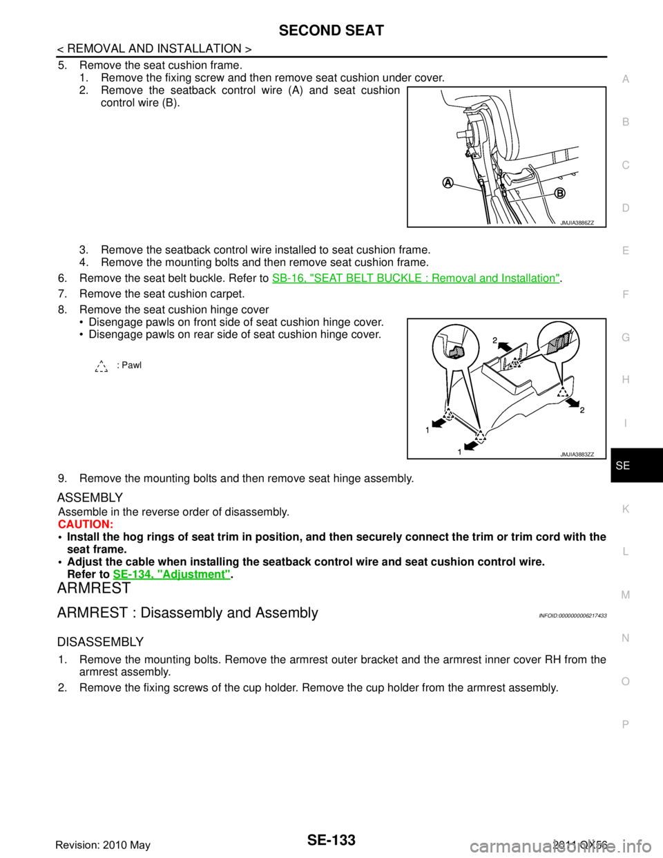
5. Remove the seat cushion frame. 1. Remove the fixing screw and then remove seat cushion under cover.
2. Remove the seatback control wire (A) and seat cushion control wire (B).
3. Remove the seatback control wire installed to seat cushion frame.
4. Remove the mounting bolts and then remove seat cushion frame.
6. Remove the seat belt buckle. Refer to SB-16, "
SEAT BELT BUCKLE : Removal and Installation".
7. Remove the seat cushion carpet.
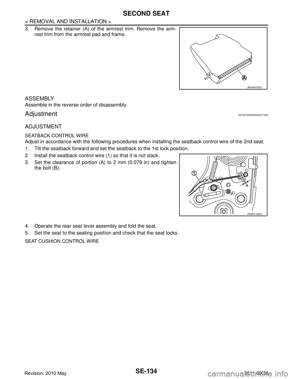
8. Remove the seat cushion hinge cover Disengage pawls on front side of seat cushion hinge cover.
Disengage pawls on rear side of seat cushion hinge cover.
9. Remove the mounting bolts and then remove seat hinge assembly.
ASSEMBLY
Assemble in the reverse order of disassembly.
CAUTION:
Install the hog rings of seat trim in position, and then securely connect the trim or trim cord with the
seat frame.
Adjust the cable when installing the seatb ack control wire and seat cushion control wire.
Refer to SE-134, "
Adjustment".
ARMREST
ARMREST : Disassembly and AssemblyINFOID:0000000006217433
DISASSEMBLY
1. Remove the mounting bolts. Remove the armrest out er bracket and the armrest inner cover RH from the
armrest assembly.
2. Remove the fixing screws of the cup holder. Remove the cup holder from the armrest assembly.
JMJIA3886ZZ
: Pawl
JMJIA3883ZZ
Revision: 2010 May2011 QX56
Page 4593 of 5598

SE-134
< REMOVAL AND INSTALLATION >
SECOND SEAT
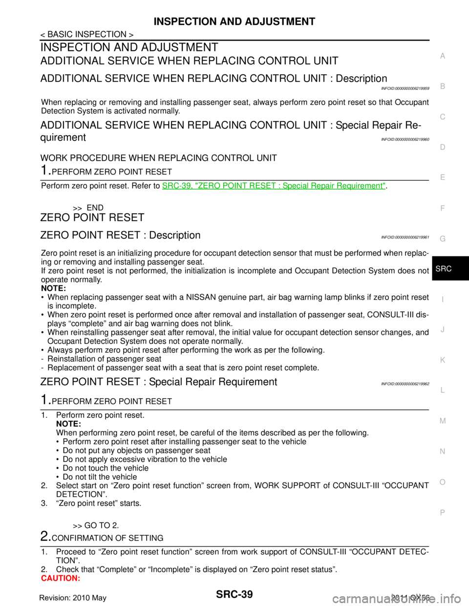
3. Remove the retainer (A) of the armrest trim. Remove the arm-rest trim from the armrest pad and frame.
ASSEMBLY
Assemble in the reverse order of disassembly.
AdjustmentINFOID:0000000006217434
ADJUSTMENT
SEATBACK CONTROL WIRE
Adjust in accordance with the following procedures when installing the seatback control wire of the 2nd seat.
1. Tilt the seatback forward and set the seatback to the 1st lock position.
2. Install the seatback control wire (1) so that it is not slack.
3. Set the clearance of portion (A) to 2 mm (0.079 in) and tighten the bolt (B).
4. Operate the rear seat leve r assembly and fold the seat.
5. Set the seat to the seating posit ion and check that the seat locks.
SEAT CUSHION CONTROL WIRE
JMJIA4075ZZ
JMJIA4136ZZ
Revision: 2010 May2011 QX56
Page 4794 of 5598

SRC-1
RESTRAINTS
C
DE
F
G
I
J
K L
M
SECTION SRC
A
B
SRC
N
O P
CONTENTS
SRS AIRBAG CONTROL SYSTEM
PRECAUTION ................ ...............................6
PRECAUTIONS .............................................. .....6
Precaution for Supplemental Restraint System
(SRS) "AIR BAG" and "SEAT BELT PRE-TEN-
SIONER" ............................................................. ......
6
Service ......................................................................6
SYSTEM DESCRIPTION ..............................8
COMPONENT PARTS ................................... .....8
Component Parts Location .................................. ......8
Component Description .............................................9
SYSTEM .............................................................11
System Diagram .................................................. ....11
System Description .................................................12
DIAGNOSIS SYSTEM (AIR BAG) .....................14
Description .......................................................... ....14
On Board Diagnosis Function .................................14
CONSULT-III Function ............................................19
DIAGNOSIS SYSTEM (OCCUPANT DETEC-
TION SYSTEM) .............................................. ....
21
CONSULT-III Function ........................................ ....21
ECU DIAGNOSIS INFORMATION ..............22
DIAGNOSIS SENSOR UNIT .......................... ....22
DTC Index .......................................................... ....22
WIRING DIAGRAM ......................................27
SRS AIR BAG SYSTEM ................................. ....27
Wiring Diagram ................................................... ....27
BASIC INSPECTION ...................................36
DIAGNOSIS AND REPAIR WORK FLOW .... ....36
Work Flow ........................................................... ....36
INSPECTION AND ADJUSTMENT ....................39
ADDITIONAL SERVICE WHEN REPLACING
CONTROL UNIT .................................................... ....
39
ADDITIONAL SERVICE WHEN REPLACING
CONTROL UNIT : Description .................................
39
ADDITIONAL SERVICE WHEN REPLACING
CONTROL UNIT : Special Repair Requirement ......
39
ZERO POINT RESET ............................................. ....39
ZERO POINT RESET : Description .........................39
ZERO POINT RESET : Special Repair Require-
ment .........................................................................
39
DTC/CIRCUIT DIAGNOSIS .........................41
B1001, B1002, B1003, B1004, B1005 DIAG-
NOSIS SENSOR UNIT ......................................
41
DTC Logic ............................................................ ....41
Diagnosis Procedure ...............................................41
B1006, B1007, B1008, B1009, B1010 DIAG-
NOSIS SENSOR UNIT ......................................
42
DTC Logic ................................................................42
Diagnosis Procedure ...............................................42
B1011, B1012, B1013, B1014, B1015 DIAG-
NOSIS SENSOR UNIT ......................................
43
DTC Logic ................................................................43
Diagnosis Procedure ...............................................43
B1017, B1020, B1021 OCCUPANT SENS C/U
...
44
Description ........................................................... ....44
DTC Logic ................................................................44
Diagnosis Procedure ...............................................44
B1018 OCCUPANT SENS ................................46
Description ........................................................... ....46
DTC Logic ................................................................46
Diagnosis Procedure ...............................................46
B1022 OCCUPANT SENS C/U .........................48
Description ...............................................................48
Revision: 2010 May2011 QX56
Page 4832 of 5598

INSPECTION AND ADJUSTMENTSRC-39
< BASIC INSPECTION >
C
DE
F
G
I
J
K L
M A
B
SRC
N
O P
INSPECTION AND ADJUSTMENT
ADDITIONAL SERVICE WHEN REPLACING CONTROL UNIT
ADDITIONAL SERVICE WHEN REPL ACING CONTROL UNIT : Description
INFOID:0000000006219959
When replacing or removing and installing passenger seat, always perform zero point reset so that Occupant
Detection System is activated normally.
ADDITIONAL SERVICE WHEN REPLACING CONTROL UNIT : Special Repair Re-
quirement
INFOID:0000000006219960
WORK PROCEDURE WHEN REPLACING CONTROL UNIT
1.PERFORM ZERO POINT RESET
Perform zero point reset. Refer to SRC-39, "
ZERO POINT RESET : Special Repair Requirement".
>> END
ZERO POINT RESET
ZERO POINT RESET : DescriptionINFOID:0000000006219961
Zero point reset is an initializing procedure for occupant detection sensor that must be performed when replac-
ing or removing and installing passenger seat.
If zero point reset is not performed, the initializati on is incomplete and Occupant Detection System does not
operate normally.
NOTE:
When replacing passenger seat with a NISSAN genuine part, air bag warning lamp blinks if zero point reset
is incomplete.
When zero point reset is performed once after removal and installation of passenger seat, CONSULT-III dis-
plays “complete” and air bag warning does not blink.
When reinstalling passenger seat after removal, the initial value for occupant detection sensor changes, and
Occupant Detection System does not operate normally.
Always perform zero point reset after performing the work as per the following.
- Reinstallation of passenger seat
- Replacement of passenger seat with a seat that is zero point reset complete.
ZERO POINT RESET : Special Repair RequirementINFOID:0000000006219962
1.PERFORM ZERO POINT RESET
1. Perform zero point reset. NOTE:
When performing zero point reset, be careful of the items described as per the following.
Perform zero point reset after installing passenger seat to the vehicle
Do not put any objects on passenger seat
Do not apply excessive vibration to the vehicle
Do not touch the vehicle
Do not tilt the vehicle
2. Select start on “Zero point reset function” scr een from, WORK SUPPORT of CONSULT-III “OCCUPANT
DETECTION”.
3. “Zero point reset” starts.
>> GO TO 2.
2.CONFIRMATION OF SETTING
1. Proceed to “Zero point reset function” screen fr om work support of CONSULT-III “OCCUPANT DETEC-
TION”.
2. Check that “Complete” or “Incomplete” is displayed on “Zero point reset status”.
CAUTION:
Revision: 2010 May2011 QX56
Page 4833 of 5598

SRC-40
< BASIC INSPECTION >
INSPECTION AND ADJUSTMENT
“Complete” is displayed on “zero point reset current status” if the seat is reinstalled by seat removal
and installation, or “zero poin t reset” is already performed.
“Zero point reset current status” displays “Incompl ete” if a new seat is installed. When turning key
switch ON without performing zero point reset, air bag warning lamp blinks. When zero point reset is
performed, air bag wa rning lamp turns OFF.
Air bag warning lamp blinks in user mode only.
Air bag sensor unit does not record whethe r or not zero point reset is performed.
Is condition
“ALREADY PERFORMED”?
YES >> Print out “ZERO POINT RESET CURRENT STATUS” screen, and inspection end.
NO >> Check condition as per the following, and perform zero point reset again. Passenger seat is occupied by an object.
Excessive vibration is applied while performing zero point reset.
Occupant detection system is malfunctioning.NOTE:
If “Incomplete” is displayed on “zero point reset cu rrent status”, zero point reset is not completed
normally. Check the condition as per the following and perform zero point reset again.
Passenger seat is occupied by an object.
Excessive vibration is applied while performing zero point reset.
Occupant detection system is malfunctioning.
Revision: 2010 May2011 QX56