2011 INFINITI QX56 instrument panel
[x] Cancel search: instrument panelPage 3099 of 5598
A/C UNIT ASSEMBLYHA-43
< REMOVAL AND INSTALLATION >
C
DE
F
G H
J
K L
M A
B
HA
N
O P
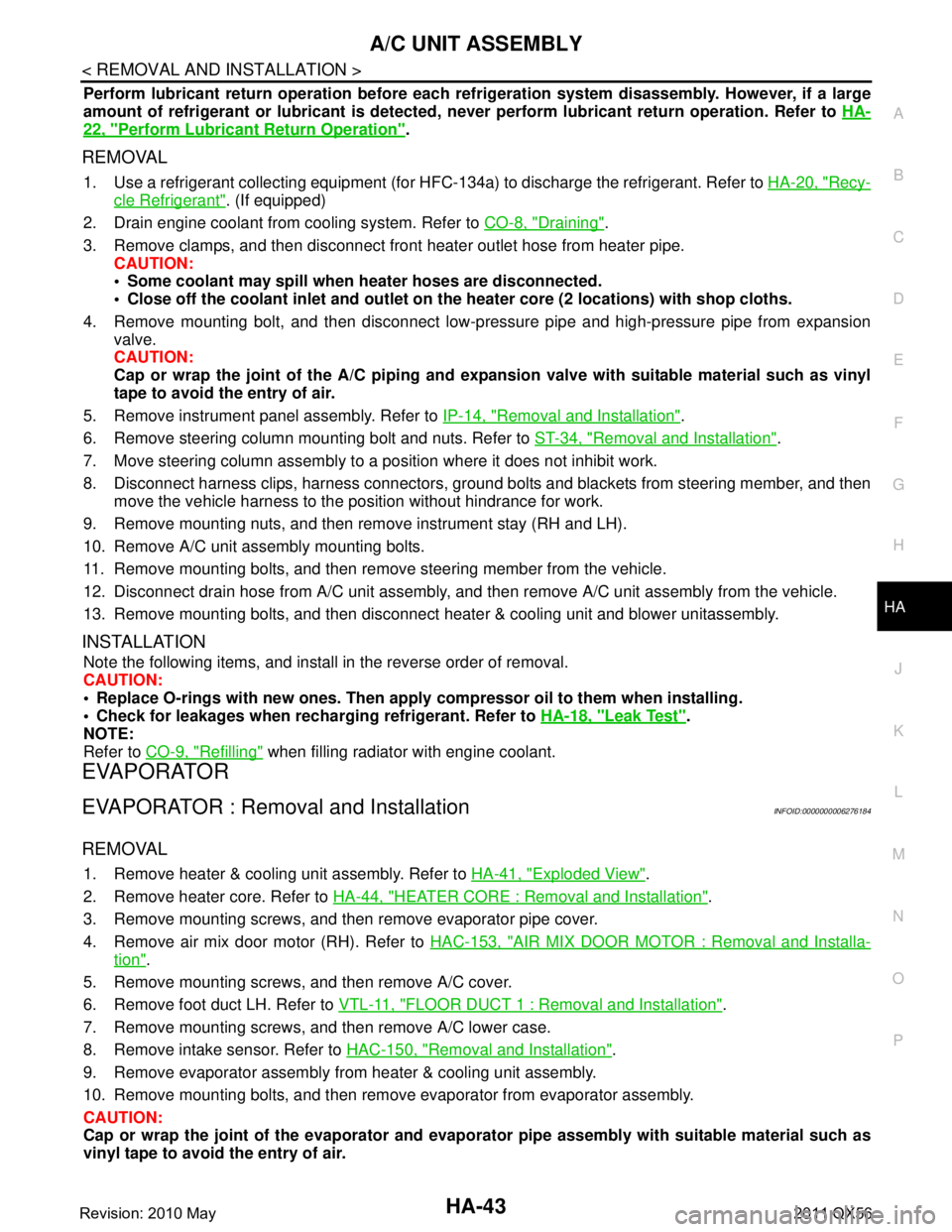
Perform lubricant return operati on before each refrigeration system disassembly. However, if a large
amount of refrigerant or lubricant is detected, n ever perform lubricant return operation. Refer to HA-
22, "Perform Lubricant Return Operation".
REMOVAL
1. Use a refrigerant collecting equipment (for HF C-134a) to discharge the refrigerant. Refer to HA-20, "Recy-
cle Refrigerant". (If equipped)
2. Drain engine coolant from cooling system. Refer to CO-8, "
Draining".
3. Remove clamps, and then disconnect front heater outlet hose from heater pipe.
CAUTION:
Some coolant may spill when heater hoses are disconnected.
Close off the coolant inlet and outlet on the heater core (2 locations) with shop cloths.
4. Remove mounting bolt, and then disconnect low-pressure pipe and high-pressure pipe from expansion valve.
CAUTION:
Cap or wrap the joint of the A/C piping and expan sion valve with suitable material such as vinyl
tape to avoid the entry of air.
5. Remove instrument panel assembly. Refer to IP-14, "
Removal and Installation".
6. Remove steering column mounting bolt and nuts. Refer to ST-34, "
Removal and Installation".
7. Move steering column assembly to a position where it does not inhibit work.
8. Disconnect harness clips, harness connectors, ground bol ts and blackets from steering member, and then
move the vehicle harness to the position without hindrance for work.
9. Remove mounting nuts, and then remove instrument stay (RH and LH).
10. Remove A/C unit assembly mounting bolts.
11. Remove mounting bolts, and then remove steering member from the vehicle.
12. Disconnect drain hose from A/C unit assembly, and then remove A/C unit assembly from the vehicle.
13. Remove mounting bolts, and then disconnect heater & cooling unit and blower unitassembly.
INSTALLATION
Note the following items, and install in the reverse order of removal.
CAUTION:
Replace O-rings with new ones. Then apply compressor oil to them when installing.
Check for leakages when recharging refrigerant. Refer to HA-18, "
Leak Test".
NOTE:
Refer to CO-9, "
Refilling" when filling radiator with engine coolant.
EVAPORATOR
EVAPORATOR : Removal and InstallationINFOID:0000000006276184
REMOVAL
1. Remove heater & cooling unit assembly. Refer to HA-41, "Exploded View".
2. Remove heater core. Refer to HA-44, "
HEATER CORE : Removal and Installation".
3. Remove mounting screws, and then remove evaporator pipe cover.
4. Remove air mix door motor (RH). Refer to HAC-153, "
AIR MIX DOOR MOTOR : Removal and Installa-
tion".
5. Remove mounting screws, and then remove A/C cover.
6. Remove foot duct LH. Refer to VTL-11, "
FLOOR DUCT 1 : Removal and Installation".
7. Remove mounting screws, and then remove A/C lower case.
8. Remove intake sensor. Refer to HAC-150, "
Removal and Installation".
9. Remove evaporator assembly from heater & cooling unit assembly.
10. Remove mounting bolts, and then remove evaporator from evaporator assembly.
CAUTION:
Cap or wrap the joint of the evaporator and evaporat or pipe assembly with suitable material such as
vinyl tape to avoid the entry of air.
Revision: 2010 May2011 QX56
Page 3254 of 5598
![INFINITI QX56 2011 Factory Service Manual
HAC-148
< REMOVAL AND INSTALLATION >[AUTOMATIC AIR CONDITIONING]
IN-VEHICLE SENSOR
IN-VEHICLE SENSOR
FRONT A/C UNIT ASSEMBLY
FRONT A/C UNIT ASSEMBLY :
Removal and InstallationINFOID:0000000006276001 INFINITI QX56 2011 Factory Service Manual
HAC-148
< REMOVAL AND INSTALLATION >[AUTOMATIC AIR CONDITIONING]
IN-VEHICLE SENSOR
IN-VEHICLE SENSOR
FRONT A/C UNIT ASSEMBLY
FRONT A/C UNIT ASSEMBLY :
Removal and InstallationINFOID:0000000006276001](/manual-img/42/57033/w960_57033-3253.png)
HAC-148
< REMOVAL AND INSTALLATION >[AUTOMATIC AIR CONDITIONING]
IN-VEHICLE SENSOR
IN-VEHICLE SENSOR
FRONT A/C UNIT ASSEMBLY
FRONT A/C UNIT ASSEMBLY :
Removal and InstallationINFOID:0000000006276001
REMOVAL
1. Remove instrument lower panel LH. Refer to IP-14, "Removal and Installation".
2. Remove fixing screw, and then remove in-vehicle sensor.
INSTALLATION
Install in the reverse order of removal.
REAR A/C UNIT ASSEMBLY
REAR A/C UNIT ASSEMBLY : Removal and InstallationINFOID:0000000006276002
REMOVAL
1. Remove rear A/C unit assembly. Refer to HA-47, "REAR A/C UNIT ASSEMBLY : Removal and Installa-
tion".
2. Remove the intake sensor from rear A/C unit assembly.
INSTALLATION
Note the following items, and install in the reverse order of removal.
CAUTION:
Replace O-rings with new ones. Then apply the compressor oil to them when installing.
Mark the mounting position of intake sensor bracket prior to removal so that the reinstalled sensor
can be located in the same position.
Never rotate the bracket insertion part when removing and installing the intake sensor.
Check for leakages when recharging refrigerant. Refer to HA-18, "
Leak Test".
Revision: 2010 May2011 QX56
Page 3259 of 5598
![INFINITI QX56 2011 Factory Service Manual
DOOR MOTORHAC-153
< REMOVAL AND INSTALLATION > [AUTOMATIC AIR CONDITIONING]
C
D
E
F
G H
J
K L
M A
B
HAC
N
O P
MODE DOOR MOTOR
MODE DOOR MOTOR : Re moval and InstallationINFOID:0000000006276009
REMOVA INFINITI QX56 2011 Factory Service Manual
DOOR MOTORHAC-153
< REMOVAL AND INSTALLATION > [AUTOMATIC AIR CONDITIONING]
C
D
E
F
G H
J
K L
M A
B
HAC
N
O P
MODE DOOR MOTOR
MODE DOOR MOTOR : Re moval and InstallationINFOID:0000000006276009
REMOVA](/manual-img/42/57033/w960_57033-3258.png)
DOOR MOTORHAC-153
< REMOVAL AND INSTALLATION > [AUTOMATIC AIR CONDITIONING]
C
D
E
F
G H
J
K L
M A
B
HAC
N
O P
MODE DOOR MOTOR
MODE DOOR MOTOR : Re moval and InstallationINFOID:0000000006276009
REMOVAL
1. Remove instrument lower panel RH. Refer to IP-14, "Removal and Installation".
2. Remove power steering control unit bracket.
3. Remove fixing screws (A), and then remove mode door motor (1).
4. Disconnect mode door motor connector.
INSTALLATION
Install in the reverse order of removal.
AIR MIX DOOR MOTOR
AIR MIX DOOR MOTOR : Re moval and InstallationINFOID:0000000006276010
REMOVAL
Driver side
1. Remove automatic drive position control unit. Refer to ADP-136, "Removal and Installation".
2. Remove fixing screws (A), and then remove air door motor LH (1).
3. Disconnect air mix door motor connector.
Passenger side
1. Remove heater core. Refer to HA-44, "HEATER CORE : Removal and Installation".
2. Remove fixing screws, and then remove air mix door motor RH.
INSTALLATION
Install in the reverse order of removal.
INTAKE DOOR MOTOR
INTAKE DOOR MOTOR : Re moval and InstallationINFOID:0000000006276011
REMOVAL
1. Remove blower unit assembly. Refer to VTL-15, "Removal and Installation".
2. Remove fixing screws, and then remove intake door motor.
1. Rear A/C unit assembly 2. Rear mode door lever 2 3. Rear mode door lever 1
4. Rear mode door motor 5. Rear air mix door motor
JMIIA0790ZZ
JMIIA0788ZZ
Revision: 2010 May2011 QX56
Page 3261 of 5598
![INFINITI QX56 2011 Factory Service Manual
IONIZER
HAC-155
< REMOVAL AND INSTALLATION > [AUTOMATIC AIR CONDITIONING]
C
D
E
F
G H
J
K L
M A
B
HAC
N
O P
IONIZER
Exploded ViewINFOID:0000000006276015
Refer to HA-41, "Exploded View".
Removal and INFINITI QX56 2011 Factory Service Manual
IONIZER
HAC-155
< REMOVAL AND INSTALLATION > [AUTOMATIC AIR CONDITIONING]
C
D
E
F
G H
J
K L
M A
B
HAC
N
O P
IONIZER
Exploded ViewINFOID:0000000006276015
Refer to HA-41, "Exploded View".
Removal and](/manual-img/42/57033/w960_57033-3260.png)
IONIZER
HAC-155
< REMOVAL AND INSTALLATION > [AUTOMATIC AIR CONDITIONING]
C
D
E
F
G H
J
K L
M A
B
HAC
N
O P
IONIZER
Exploded ViewINFOID:0000000006276015
Refer to HA-41, "Exploded View".
Removal and InstallationINFOID:0000000006276016
Removal
1. Remove instrument lower panel LH. Refer to IP-14, "Removal and Installation".
2. Remove mounting screws, and then remove ionizer from A/C unit assembly. CAUTION:
Never tough the surface (ceramic part) of th e ionizer. It is the discharge electrode.
3. Disconnect ionizer harness connector.
INSTALLATION
Note the following item, install in the reverse order of removal.
CAUTION:
If there is dirt, use a clean clot h and clean the discharge electrode (ceramic part) of the ionizer.
Revision: 2010 May2011 QX56
Page 3338 of 5598
FOOT LAMPINL-71
< REMOVAL AND INSTALLATION >
C
DE
F
G H
I
J
K
M A
B
INL
N
O P
FOOT LAMP
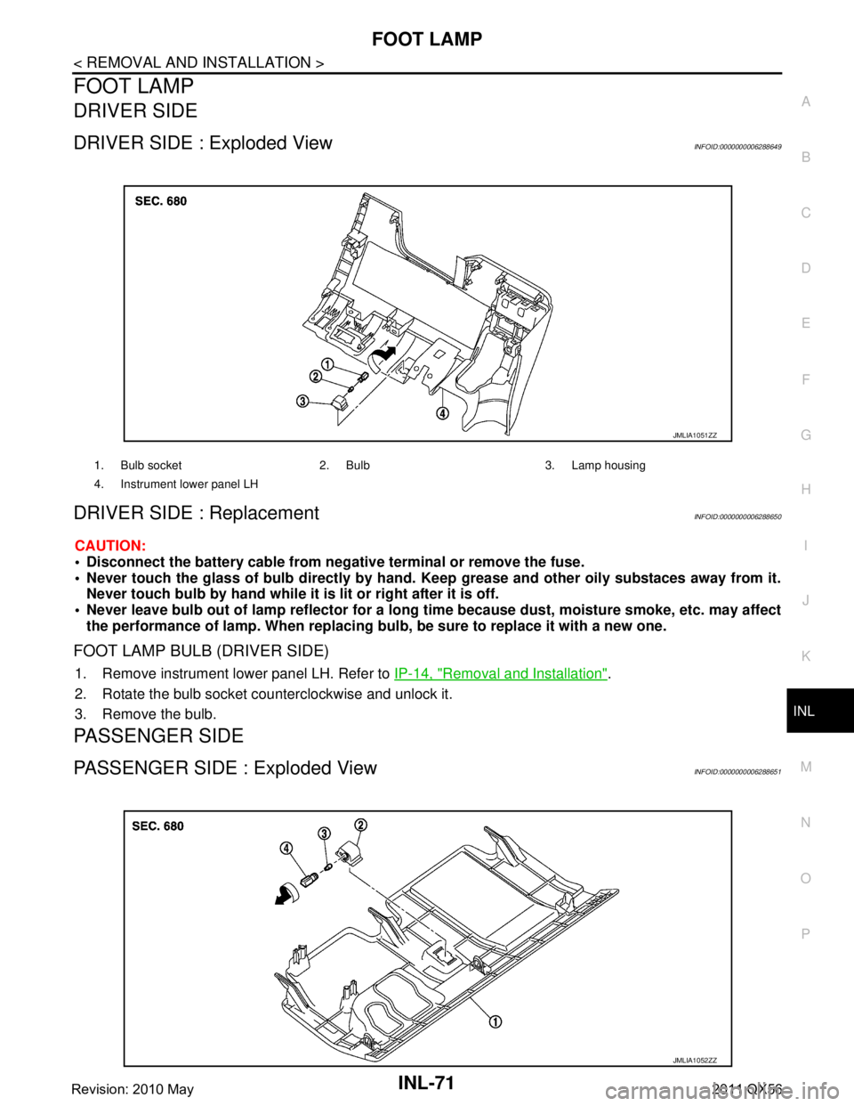
DRIVER SIDE
DRIVER SIDE : Exploded ViewINFOID:0000000006288649
DRIVER SIDE : ReplacementINFOID:0000000006288650
CAUTION:
Disconnect the battery cable from negative terminal or remove the fuse.
Never touch the glass of bulb directly by hand. Keep grease and other oily substaces away from it.
Never touch bulb by hand while it is lit or right after it is off.
Never leave bulb out of lamp reflector for a long time because dust, moisture smoke, etc. may affect
the performance of lamp. When replacing bu lb, be sure to replace it with a new one.
FOOT LAMP BULB (DRIVER SIDE)
1. Remove instrument lower panel LH. Refer to IP-14, "Removal and Installation".
2. Rotate the bulb socket counterclockwise and unlock it.
3. Remove the bulb.
PASSENGER SIDE
PASSENGER SIDE : Exploded ViewINFOID:0000000006288651
1. Bulb socket 2. Bulb 3. Lamp housing
4. Instrument lower panel LH
JMLIA1051ZZ
JMLIA1052ZZ
Revision: 2010 May2011 QX56
Page 3358 of 5598
SQUEAK AND RATTLE TROUBLE DIAGNOSESINT-9
< SYMPTOM DIAGNOSIS >
C
DE
F
G H
I
K L
M A
B
INT
N
O P
Used to insulate where movement does not occur. Ideal for instrument panel applications.
68370-4B000: 15 ×25 mm (0.591 ×0.984 in) pad
68239-13E00: 5 mm (0.197 in) wide tape roll
The following materials, not found in the kit, can also be used to repair squeaks and rattles.
UHMW (TEFLON) TAPE
Insulates where slight movement is present. Ideal for instrument panel applications.
SILICONE GREASE
Used in place of UHMW tape that is visible or does not fit. Only lasts a few months.
SILICONE SPRAY
Used when grease cannot be applied.
DUCT TAPE
Used to eliminate movement.
CONFIRM THE REPAIR
After repair is complete, test drive the vehicle to confi rm that the cause of noise is repaired by test driving the
vehicle. Operate the vehicle under the same conditions as when the noise originally occurred. Refer to the
notes on the Diagnostic Worksheet.
Inspection ProcedureINFOID:0000000006220270
Refer to Table of Contents for specific component removal and installation information.
INSTRUMENT PANEL
Most incidents are caused by contact and movement between:
1. The cluster lid A and instrument panel
2. Acrylic lens and combination meter housing
3. Instrument panel to front pillar garnish
4. Instrument panel to windshield
5. Instrument panel mounting pins
6. Wiring harnesses behind the combination meter
7. A/C defroster duct and duct joint
These incidents can usually be located by tapping or moving the components to duplicate the noise or by
pressing on the components while driving to stop the noise. Most of these incidents can be repaired by
applying felt cloth tape or silicon spray (in hard to reach areas). Urethane pads can be used to insulate
wiring harness.
CAUTION:
Never use silicone spray to isolate a squeak or ra ttle. If the area is saturated with silicone, the
recheck of repair becomes impossible.
CENTER CONSOLE
Components to check include:
1. Shifter assembly cover to finisher
2. A/C control unit and cluster lid C
3. Wiring harnesses behind audio and A/C control unit
The instrument panel repair and isolation pr ocedures also apply to the center console.
DOORS
Check the following items:
1. Finisher and inner panel making a slapping noise
2. Inside handle escutcheon connection to door finisher
3. Wiring harnesses tapping
4. Door striker out of alignment causing a popping noise on starts and stops
Tapping, moving the components, or pressing on them while driving to duplicate the conditions can isolate
many of these incidents. The areas can usually be insula ted with felt cloth tape or insulator foam blocks from
the NISSAN Squeak and Rattle Kit (J-43980) to repair the noise.
TRUNK
Trunk noises are often caused by a loose jack or loose items put into the trunk by the customer.
In addition check for the following items:
Revision: 2010 May2011 QX56
Page 3374 of 5598
FLOOR TRIMINT-25
< REMOVAL AND INSTALLATION >
C
DE
F
G H
I
K L
M A
B
INT
N
O P
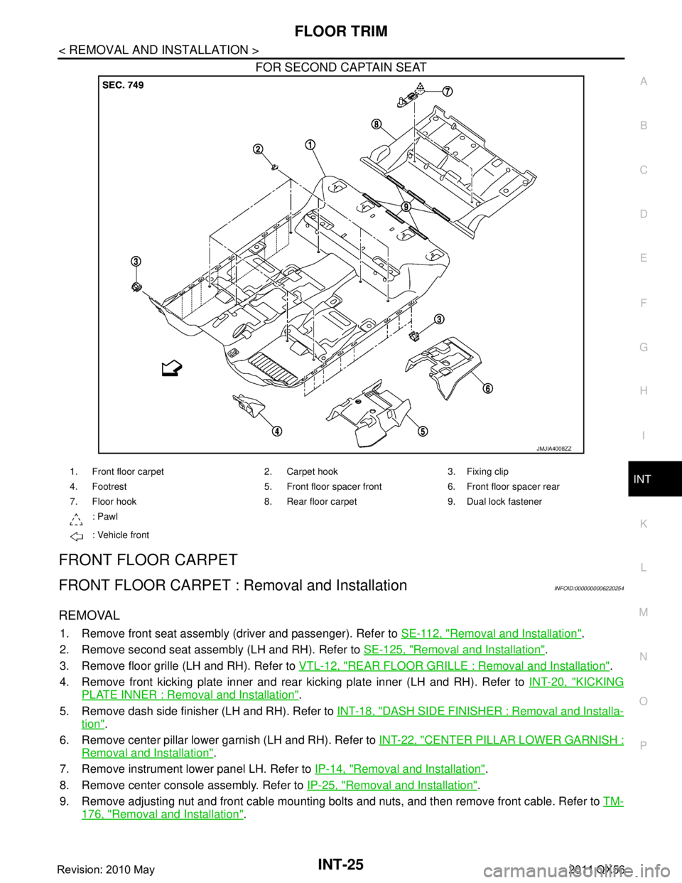
FOR SECOND CAPTAIN SEAT
FRONT FLOOR CARPET
FRONT FLOOR CARPET : Re moval and InstallationINFOID:0000000006220254
REMOVAL
1. Remove front seat assembly (driver and passenger). Refer to SE-112, "Removal and Installation".
2. Remove second seat assembly (LH and RH). Refer to SE-125, "
Removal and Installation".
3. Remove floor grille (LH and RH). Refer to VTL-12, "
REAR FLOOR GRILLE : Removal and Installation".
4. Remove front kicking plate inner and rear kicking plate inner (LH and RH). Refer to INT-20, "
KICKING
PLATE INNER : Removal and Installation".
5. Remove dash side finisher (LH and RH). Refer to INT-18, "
DASH SIDE FINISHER : Removal and Installa-
tion".
6. Remove center pillar lower garnish (LH and RH). Refer to INT-22, "
CENTER PILLAR LOWER GARNISH :
Removal and Installation".
7. Remove instrument lower panel LH. Refer to IP-14, "
Removal and Installation".
8. Remove center console assembly. Refer to IP-25, "
Removal and Installation".
9. Remove adjusting nut and front cable mounting bolts and nuts, and then remove front cable. Refer to TM-
176, "Removal and Installation".
JMJIA4008ZZ
1. Front floor carpet 2. Carpet hook 3. Fixing clip
4. Footrest 5. Front floor spacer front 6. Front floor spacer rear
7. Floor hook 8. Rear floor carpet 9. Dual lock fastener
: Pawl
: Vehicle front
Revision: 2010 May2011 QX56
Page 3391 of 5598
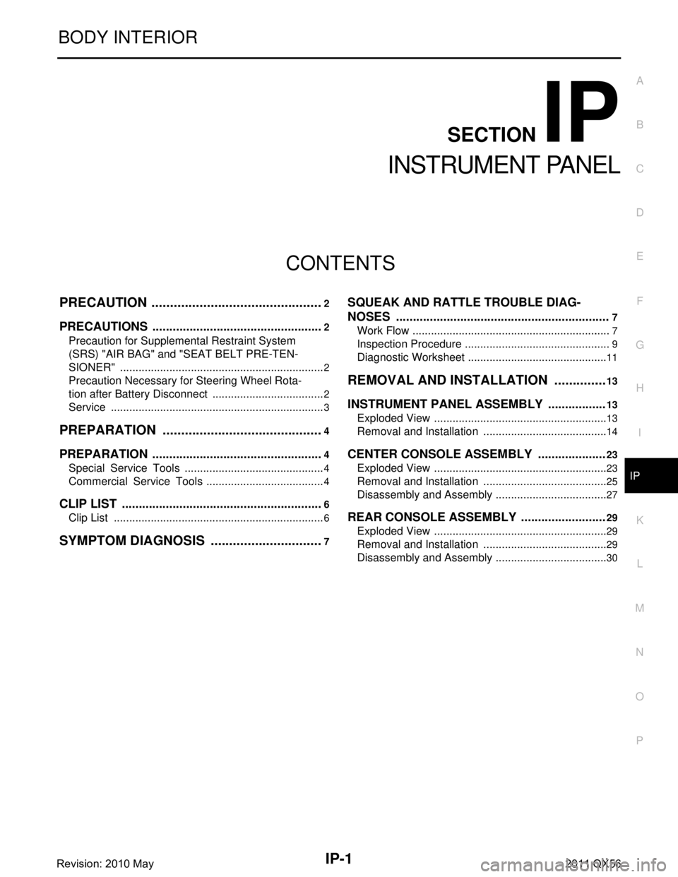
IP-1
BODY INTERIOR
C
DE
F
G H
I
K L
M
SECTION IP
A
B
IP
N
O P
CONTENTS
INSTRUMENT PANEL
PRECAUTION ................ ...............................2
PRECAUTIONS .............................................. .....2
Precaution for Supplemental Restraint System
(SRS) "AIR BAG" and "SEAT BELT PRE-TEN-
SIONER" ............................................................. ......
2
Precaution Necessary for Steering Wheel Rota-
tion after Battery Disconnect .....................................
2
Service ......................................................................3
PREPARATION ............................................4
PREPARATION .............................................. .....4
Special Service Tools ........................................ ......4
Commercial Service Tools .......................................4
CLIP LIST ............................................................6
Clip List ............................................................... ......6
SYMPTOM DIAGNOSIS ...............................7
SQUEAK AND RATTLE TROUBLE DIAG-
NOSES ...............................................................
7
Work Flow ............................................................ .....7
Inspection Procedure ................................................9
Diagnostic Worksheet ..............................................11
REMOVAL AND INSTALLATION ...............13
INSTRUMENT PANEL ASSEMBLY .................13
Exploded View ..................................................... ....13
Removal and Installation .........................................14
CENTER CONSOLE ASSEMBLY ....................23
Exploded View .........................................................23
Removal and Installation .........................................25
Disassembly and Assembly .....................................27
REAR CONSOLE ASSEMBLY .........................29
Exploded View .........................................................29
Removal and Installation .........................................29
Disassembly and Assembly .....................................30
Revision: 2010 May2011 QX56