Page 5395 of 5598

DUCT AND GRILLEVTL-9
< REMOVAL AND INSTALLATION >
C
DE
F
G H
J
K L
M A
B
VTL
N
O P
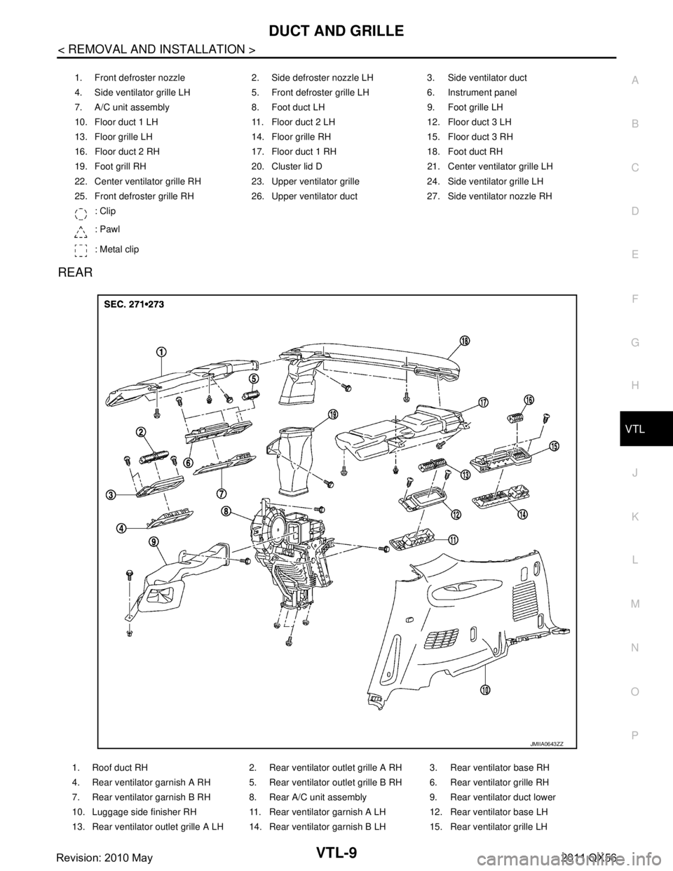
REAR
1. Front defroster nozzle 2. Side defroster nozzle LH 3. Side ventilator duct
4. Side ventilator grille LH 5. Front defroster grille LH 6. Instrument panel
7. A/C unit assembly 8. Foot duct LH 9. Foot grille LH
10. Floor duct 1 LH 11. Floor duct 2 LH 12. Floor duct 3 LH
13. Floor grille LH 14. Floor grille RH 15. Floor duct 3 RH
16. Floor duct 2 RH 17. Floor duct 1 RH 18. Foot duct RH
19. Foot grill RH 20. Cluster lid D 21. Center ventilator grille LH
22. Center ventilator grille RH 23. Upper ventilator grille 24. Side ventilator grille LH
25. Front defroster grille RH 26. Upper ventilator duct 27. Side ventilator nozzle RH : Clip
: Pawl
: Metal clip
1. Roof duct RH 2. Rear ventilator outlet grille A RH 3. Rear ventilator base RH
4. Rear ventilator garnish A RH 5. Rear ventilator outlet grille B RH 6. Rear ventilator grille RH
7. Rear ventilator garnish B RH 8. Rear A/C unit assembly 9. Rear ventilator duct lower
10. Luggage side finisher RH 11. Rear ventilator garnish A LH 12. Rear ventilator base LH
13. Rear ventilator outlet grille A LH 14. Rear ventilator garnish B LH 15. Rear ventilator grille LH
JMIIA0643ZZ
Revision: 2010 May2011 QX56
Page 5396 of 5598

VTL-10
< REMOVAL AND INSTALLATION >
DUCT AND GRILLE
CENTER VENTILAT O R G R I L L E
CENTER VENTILATOR GRILLE : Removal and InstallationINFOID:0000000006276287
REMOVAL
1. Remove cluster lid D. Refer to IP-14, "Removal and Installation".
2. Remove center ventilator grille from cluster lid D.
INSTALLATION
Install in the reverse order of removal.
SIDE VENTILATOR GRILLE
SIDE VENTILATOR GRILLE : Removal and InstallationINFOID:0000000006276288
REMOVAL
1. Remove instrument panel assembly. Refer to IP-14, "Removal and Installation".
2. Remove fixing screw, and then remove side ventilator grille from instrument panel.
INSTALLATION
Install in the reverse order of removal.
FRONT DEFROSTER GRILLE
FRONT DEFROSTER GRILLE : Removal and InstallationINFOID:0000000006276289
REMOVAL
Remove front defroster grilles, using remover tools.
INSTALLATION
Install in the reverse order of removal.
UPPER VENTILATOR GRILLE
UPPER VENTILATOR GRILLE : Removal and InstallationINFOID:0000000006276290
REMOVAL
Remove upper ventilator grille, using remover tools.
INSTALLATION
Install in the reverse order of removal.
SIDE VENTILATOR DUCT
SIDE VENTILATOR DUCT : Removal and InstallationINFOID:0000000006276291
REMOVAL
1. Remove instrument panel assembly. Refer to IP-14, "Removal and Installation".
2. Remove fixing screws, and then remove side ventilator duct from instrument panel.
INSTALLATION
Install in the reverse order of removal.
UPPER VENTILATOR DUCT
UPPER VENTILATOR DUCT : Removal and InstallationINFOID:0000000006276292
REMOVAL
1. Remove instrument panel assembly. Refer to IP-14, "Removal and Installation".
16. Rear ventilator outlet grille B LH 17. Roof duct LH Roof duct center
19. Rear ventilator duct upper
Revision: 2010 May2011 QX56
Page 5397 of 5598

DUCT AND GRILLEVTL-11
< REMOVAL AND INSTALLATION >
C
DE
F
G H
J
K L
M A
B
VTL
N
O P
2. Remove front defroster nozzle. Refer to VTL-11, "FRONT DEFROSTER NOZZLE : Removal and Installa-
tion".
3. Remove fixing screws, and then remove upper ventilator duct.
INSTALLATION
Install in the reverse order of removal.
FRONT DEFROSTER NOZZLE
FRONT DEFROSTER NOZZLE : Removal and InstallationINFOID:0000000006276293
REMOVAL
1. Remove instrument panel assembly. Refer to VTL-8, "Exploded View".
2. Remove fixing screws, and then remove front defroster nozzle.
INSTALLATION
Install in the reverse order of removal.
SIDE DEFROSTER NOZZLE
SIDE DEFROSTER NOZZLE : Removal and InstallationINFOID:0000000006276294
REMOVAL
1. Remove instrument panel assembly. Refer to IP-14, "Removal and Installation".
2. Remove fixing screw, and then remove side defroster nozzle.
INSTALLATION
Install in the reverse order of removal.
FLOOR DUCT 1
FLOOR DUCT 1 : Removal and InstallationINFOID:0000000006276295
REMOVAL
1. Remove center console assembly. Refer to IP-25, "Removal and Installation".
2. Remove floor duct 1.
INSTALLATION
Install in the reverse order of removal.
FLOOR DUCT 2
FLOOR DUCT 2 : Removal and InstallationINFOID:0000000006276296
REMOVAL
1. Pull up front of front floor carpet of securing work space. Refer to INT-25, "FRONT FLOOR CARPET :
Removal and Installation".
2. Remove fixing clip, and then remove floor duct 2.
INSTALLATION
Install in the reverse order of removal.
FLOOR DUCT 3
FLOOR DUCT 3 : Removal and InstallationINFOID:0000000006276297
REMOVAL
1. Pull up front of front floor carpet of securing work space. Refer to INT-25, "FRONT FLOOR CARPET :
Removal and Installation".
2. Remove mounting bolt, and then remove floor duct 1.
INSTALLATION
Revision: 2010 May2011 QX56
Page 5398 of 5598

VTL-12
< REMOVAL AND INSTALLATION >
DUCT AND GRILLE
Install in the reverse order of removal.
REAR FLOOR GRILLE
REAR FLOOR GRILLE : Removal and InstallationINFOID:0000000006276298
REMOVAL
Disengage fixing metal clips, and then remove rear floor grille.
INSTALLATION
Install in the reverse order of removal.
FOOT DUCT
FOOT DUCT : Removal and InstallationINFOID:0000000006276299
REMOVAL
1. Remove steering member. Refer to HA-42, "HEATER & COOLING UNIT ASSEMBLY : Removal and
Installation".
2. Remove fixing screws, and then remove foot duct.
INSTALLATION
Install in the reverse order of removal.
FOOT GRILLE
FOOT GRILLE : Removal and InstallationINFOID:0000000006276300
REMOVAL
Driver side
1. Remove instrument lower panel RH. Refer to IP-14, "Removal and Installation".
2. Remove fixing screws, and then remove foot grille.
Passenger side
1. Remove instrument lower cover. Refer to IP-14, "Removal and Installation".
2. Remove fixing screws and clip, and then remove foot grille.
INSTALLATION
Install in the reverse order of removal.
REAR VENTILATOR DUCT LOWER
REAR VENTILATOR DUCT LOWER : Removal and InstallationINFOID:0000000006276301
REMOVAL
1. Remove luggage side lower finisher RH. Refer to INT-36, "LUGGAGE SIDE LOWER FINISHER :
Removal and Installation".
2. Remove mounting bolts, and then remove rear ventilator duct lower.
INSTALLATION
Install in the reverse order of removal.
REAR VENTILATOR DUCT UPPER
REAR VENTILATOR DUCT UPPER : Removal and InstallationINFOID:0000000006276302
REMOVAL
1. Remove back pillar garnish RH. Refer to INT-37, "BACK PILLAR GARNISH : Removal and Installation".
2. Remove mounting bolt, and then remove rear ventilator grille upper.
INSTALLATION
Install in the reverse order of removal.
Revision: 2010 May2011 QX56
Page 5515 of 5598
LOW TIRE PRESSURE WARNING CONTROL UNIT
WT-65
< REMOVAL AND INSTALLATION >
C
D F
G H
I
J
K L
M A
B
WT
N
O P
LOW TIRE PRESSURE WA RNING CONTROL UNIT
Exploded ViewINFOID:0000000006225550
Removal and InstallationINFOID:0000000006225551
REMOVAL
1. Remove the glove box assembly. Refer to IP-14, "Removal and Installation".
2. Remove the instrument lower panel RH. Refer to IP-14, "
Removal and Installation".
3. Disconnect low tire pressure warning control unit connector.
4. Remove the low tire pressure warning control unit control unit.
INSTALLATION
Note the following, install in the reverse order of removal.
Perform ID registration after replacing low tire pressure warning control unit. Refer to WT-29, "
Work Proce-
dure".
1. Low tire pressure warning control unit 2. Bracket
: Vehicle front
Refer to GI-4, "
Components" for symbols in the figure.
JPEIC0072ZZ
Revision: 2010 May2011 QX56