2011 INFINITI QX56 ABS
[x] Cancel search: ABSPage 3831 of 5598
MWI-88
< REMOVAL AND INSTALLATION >
CLOCK
CLOCK
Exploded ViewINFOID:0000000006221783
REMOVAL
Refer to IP-13, "Exploded View".
Removal and InstallationINFOID:0000000006221784
REMOVAL
1. Remove cluster lid C assembly. Refer to IP-14, "Removal and Installation".
2. Disengage the tabs to separate clock.
INSTALLATION
Install in the reverse order of removal.
Revision: 2010 May2011 QX56
Page 3883 of 5598
![INFINITI QX56 2011 Factory Service Manual
PCS-42
< SYSTEM DESCRIPTION >[POWER DISTRIBUTION SYSTEM]
DIAGNOSIS SYSTEM (BCM)
SELF-DIAG RESULT
Refer to
BCS-57, "DTCIndex".
DATA MONITOR
PW DOWN SET Unlock button pressing time on Intelligent Key INFINITI QX56 2011 Factory Service Manual
PCS-42
< SYSTEM DESCRIPTION >[POWER DISTRIBUTION SYSTEM]
DIAGNOSIS SYSTEM (BCM)
SELF-DIAG RESULT
Refer to
BCS-57, "DTCIndex".
DATA MONITOR
PW DOWN SET Unlock button pressing time on Intelligent Key](/manual-img/42/57033/w960_57033-3882.png)
PCS-42
< SYSTEM DESCRIPTION >[POWER DISTRIBUTION SYSTEM]
DIAGNOSIS SYSTEM (BCM)
SELF-DIAG RESULT
Refer to
BCS-57, "DTCIndex".
DATA MONITOR
PW DOWN SET Unlock button pressing time on Intelligent Key button can be selected from the following with
this mode
MODE 1: 3 sec
MODE 2: Non-operation
MODE 3: 5 sec
WELCOME LIGHT SELECT Welcome light function mode can be selected from the following with this mode
Puddle/Outside Handle
Room lamp
Head & Tail Lamps (this item is displayed, but cannot be used)
Heart Beat
WELCOME LIGHT OP SET Welcome light function mode can be changed to operation with this mode
On: Operate
Off: Non-operation
Monitor item Description
Monitor Item Condition
REQ SW -DR Indicates [On/Off] condition of door request switch (driver side)
REQ SW -AS Indicates [On/Off] condition of door request switch (passenger side)
REQ SW -BD/TR Indicates [On/Off] condition of back door request switch
PUSH SW Indicates [On/Off] condition of push-button ignition switch
CLUTCH SW NOTE:
This item is displayed, but cannot be monitored
BRAKE SW 1 Indicates [On/Off]* condition of stop lamp switch power supply
BRAKE SW 2 Indicates [On/Off] condition of stop lamp switch
DETE/CANCL SW Indicates [On/Off] condition of P position
SFT PN/N SW Indicates [On/Off] condition of P or N position
S/L -LOCK Indicates [On/Off] condition of steering lock unit (LOCK)
S/L -UNLOCK Indicates [On/Off] condition of steering lock unit (UNLOCK)
S/L RELAY -F/B Indicates [On/Off] condition of steering lock relay
UNLK SEN -DR Indicates [On/Off] condition of driver door UNLOCK status
PUSH SW -IPDM Indicates [On/Off] condition of push-button ignition switch
IGN RLY1 -F/B Indicates [On/Off] condition of ignition relay 1
DETE SW -IPDM Indicates [On/Off] condition of P position
SFT PN -IPDM Indicates [On/Off] condition of P or N position
SFT P -MET Indicates [On/Off] condition of P position
SFT N -MET Indicates [On/Off] condition of N position
ENGINE STATE Indicates [Stop/Stall/Crank/Run] condition of engine states
S/L LOCK-IPDM Indicates [On/Off] condition of steering lock unit (LOCK)
S/L UNLK-IPDM Indicates [On/Off] condition of steering lock unit (UNLOCK)
S/L RELAY-REQ Indicates [On/Off] condition of steering lock relay
VEH SPEED 1 Display the vehicle speed signal received from combination meter by numerical value [Km/h]
VEH SPEED 2 Display the vehi cle speed signal received from ABS or VDC or TCM by numerical value [Km/h]
DOOR STAT-DR Indicates [LOCK/READY/UNLK] condition of unlock sensor
DOOR STAT-AS Indicates [LOCK/READY/UNLK] condition of passenger side door status
ID OK FLAG Indicates [Set/Reset] condition of key ID
PRMT ENG STRT Indicates [Set/Reset] condition of engine start possibility
Revision: 2010 May2011 QX56
Page 3926 of 5598
![INFINITI QX56 2011 Factory Service Manual
PG
COMPONENT PARTSPG-7
< SYSTEM DESCRIPTION >
C
DE
F
G H
I
J
K L
B A
O P
N
[Example]
HARNESS CONNECTOR (LEVER LOCKING TYPE)
Lever locking type harness connectors are used on cert
ain control units INFINITI QX56 2011 Factory Service Manual
PG
COMPONENT PARTSPG-7
< SYSTEM DESCRIPTION >
C
DE
F
G H
I
J
K L
B A
O P
N
[Example]
HARNESS CONNECTOR (LEVER LOCKING TYPE)
Lever locking type harness connectors are used on cert
ain control units](/manual-img/42/57033/w960_57033-3925.png)
PG
COMPONENT PARTSPG-7
< SYSTEM DESCRIPTION >
C
DE
F
G H
I
J
K L
B A
O P
N
[Example]
HARNESS CONNECTOR (LEVER LOCKING TYPE)
Lever locking type harness connectors are used on cert
ain control units and control modules such as ECM,
ABS actuator and electric unit (control unit), etc.
Lever locking type harness connectors are also us ed on super multiple junction (SMJ) connectors.
Always confirm the lever is fully locked in place by mo ving the lever as far as it will go to ensure full connec-
tion.
CAUTION:
SEL769V
Revision: 2010 May2011 QX56
Page 4256 of 5598

RSU-1
SUSPENSION
C
DF
G H
I
J
K L
M
SECTION RSU
A
B
RSU
N
O PCONTENTS
REAR SUSPENSION
PRECAUTION ................ ...............................2
PRECAUTIONS .............................................. .....2
Precautions for Suspension ................................ ......2
PREPARATION ............................................3
PREPARATION .............................................. .....3
Special Service Tools .......................................... ......3
Commercial Service Tools ........................................3
SYMPTOM DIAGNOSIS ...............................4
NOISE, VIBRATION AND HARSHNESS
(NVH) TROUBLESHOOTING ........................ .....
4
NVH Troubleshooting Chart ................................ ......4
PERIODIC MAINTENANCE ..........................5
REAR SUSPENSION ASSEMBLY ................ .....5
Inspection ............................................................ ......5
WHEEL ALIGNMENT ..........................................6
Inspection ............................................................ ......6
Adjustment ................................................................6
REMOVAL AND INSTALLATION ................8
REAR LOWER LINK & COIL SPRING .......... .....8
Exploded View .................................................... ......8
Removal and Installation ...........................................8
Inspection ..................................................................9
REAR SHOCK ABSORBER ..............................10
Exploded View .................................................... ....10
Removal and Installation ..................................... ....10
Inspection and Adjustment ......................................11
Disposal ...................................................................12
SUSPENSION ARM ..........................................13
Exploded View .........................................................13
Removal and Installation .........................................13
Inspection and Adjustment ......................................13
FRONT LOWER LINK .......................................15
Exploded View .........................................................15
Removal and Installation .........................................15
Inspection ................................................................15
REAR STABILIZER ..........................................17
Exploded View .........................................................17
Removal and Installation .........................................17
Inspection ................................................................17
UNIT REMOVAL AND INSTALLATION ......18
REAR SUSPENSION MEMBER .......................18
Exploded View ..................................................... ....18
Removal and Installation .........................................18
Inspection and Adjustment ......................................19
SERVICE DATA AND SPECIFICATIONS
(SDS) ............... .............................................
20
SERVICE DATA AND SPECIFICATIONS
(SDS) .................................................................
20
Wheel Alignment ................................................. ....20
Ball Joint ..................................................................20
Wheel Height ...........................................................20
Revision: 2010 May2011 QX56
Page 4259 of 5598
RSU-4
< SYMPTOM DIAGNOSIS >
NOISE, VIBRATION AND HARSHNESS (NVH) TROUBLESHOOTING
SYMPTOM DIAGNOSIS
NOISE, VIBRATION AND HARSHNESS (NVH) TROUBLESHOOTING
NVH Troubleshooting ChartINFOID:0000000006225659
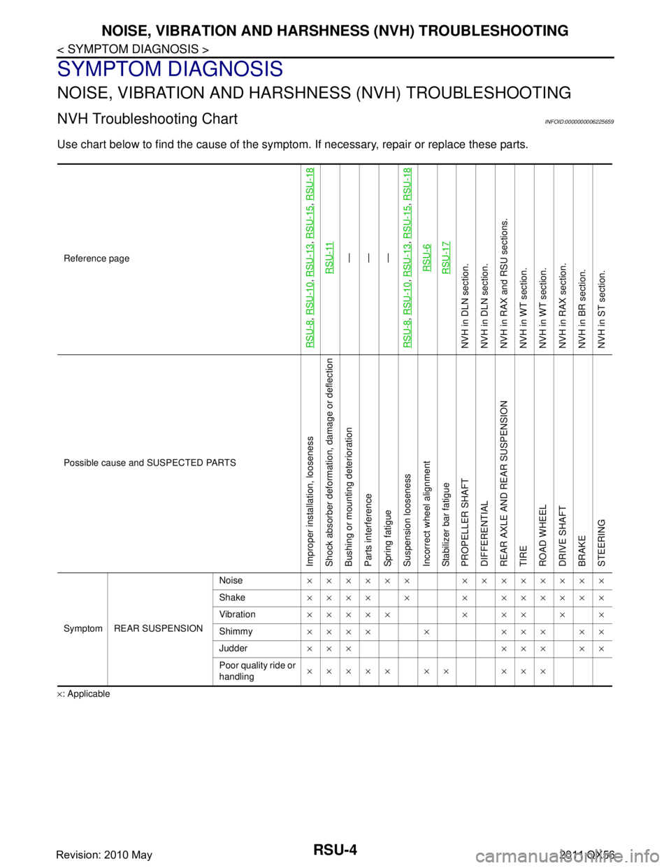
Use chart below to find the cause of the symptom. If necessary, repair or replace these parts.
×: ApplicableReference page
RSU-8
,
RSU-10
, RSU-13
, RSU-15
, RSU-18
RSU-11
—
—
—
RSU-8
, RSU-10
, RSU-13
, RSU-15
, RSU-18
RSU-6RSU-17
NVH in DLN section.
NVH in DLN section.
NVH in RAX and RSU sections.
NVH in WT section.
NVH in WT section.
NVH in RAX section.
NVH in BR section.
NVH in ST section.
Possible cause and SUSPECTED PARTS
Improper installation, looseness
Shock absorber deformation, damage or deflection
Bushing or mounting deterioration
Parts interference
Spring fatigue
Suspension looseness
Incorrect wheel alignment
Stabilizer bar fatigue
PROPELLER SHAFT
DIFFERENTIAL
REAR AXLE AND REAR SUSPENSION
TIRE
ROAD WHEEL
DRIVE SHAFT
BRAKE
STEERING
Symptom REAR SUSPENSION Noise
×××××× ××××××××
Shake ×××× × × ××××××
Vibration ××××× × ×× × ×
Shimmy ×××× × ××× ××
Judder ××× ××× ××
Poor quality ride or
handling ××××× ×× ×××
Revision: 2010 May2011 QX56
Page 4260 of 5598
REAR SUSPENSION ASSEMBLYRSU-5
< PERIODIC MAINTENANCE >
C
DF
G H
I
J
K L
M A
B
RSU
N
O P
PERIODIC MAINTENANCE
REAR SUSPENSION ASSEMBLY
InspectionINFOID:0000000006225660
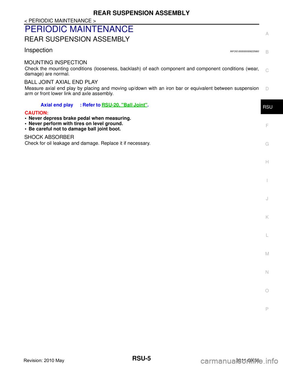
MOUNTING INSPECTION
Check the mounting conditions (looseness, backlash) of each component and component conditions (wear,
damage) are normal.
BALL JOINT AXIAL END PLAY
Measure axial end play by placing and moving up/down with an iron bar or equivalent between suspension
arm or front lower link and axle assembly.
CAUTION:
• Never depress brake pedal when measuring.
Never perform with tires on level ground.
Be careful not to damage ball joint boot.
SHOCK ABSORBER
Check for oil leakage and damage. Replace it if necessary. Axial end play : Refer to
RSU-20, "
Ball Joint".
Revision: 2010 May2011 QX56
Page 4261 of 5598
RSU-6
< PERIODIC MAINTENANCE >
WHEEL ALIGNMENT
WHEEL ALIGNMENT
InspectionINFOID:0000000006225661
DESCRIPTION
Measure wheel alignment under unladen conditions.
NOTE:
“Unladen conditions” means that fuel, engine coolant, and lubricant are full. Spare tire, jack, hand tools and
mats are in designated positions.
PRELIMINARY CHECK
Check the following:
Tires for improper air pressure and wear
Road wheels for runout. Refer to WT-64, "
Inspection".
Wheel bearing axial end play. Refer to RAX-5, "
Inspection".
Ball joint axial end play of suspension arm and front lower link. Refer to RSU-20, "
Ball Joint".
Shock absorber operation
Each mounting point of axle and suspension for looseness and deformation
Each of front lower link, rear lower link, rear suspension member, suspension arm and shock absorber for
cracks, deformation, and other damage
Vehicle height (posture)
GENERAL INFORMATION AND RECOMMENDATIONS
A four-wheel thrust alignment should be performed.
- This type of alignment is recomm ended for any NISSAN/INFINITI vehicle.
- The four-wheel “thrust” process helps ensure that t he vehicle is properly aligned and the steering wheel is
centered.
- The alignment rack itself should be capable of accepting any NISSAN/INFINITI vehicle.
- The rack should be checked to ensure that it is level.
Make sure the machine is properly calibrated.
- Your alignment equipment should be regularly calib rated in order to give correct information.
- Check with the manufacturer of your specific equi pment for their recommended Service/Calibration Sched-
ule.
ALIGNMENT PROCESS
IMPORTANT:
Use only the alignment specifications listed in this Service Manual.
When displaying the alignment settings, many alignment machines use “indicators”: (Green/red, plus or
minus, Go/No Go). Never use these indicators.
- The alignment specifications programmed into your machine that operate these indicators may not be cor-
rect.
- This may result in an ERROR.
Some newer alignment machines are equipped with an optional “Rolling Compensation” method to “com- pensate” the sensors (alignment targets or head units). Never use this “Rolling Compensation” method.
- Use the “Jacking Compensation Method”. After installi ng the alignment targets or head units, raise the vehi-
cle and rotate the wheels 1/2 turn both ways.
- See Instructions in the alignment machine you're using for more information on this.
AdjustmentINFOID:0000000006225662
CAMBER
Revision: 2010 May2011 QX56
Page 4265 of 5598
RSU-10
< REMOVAL AND INSTALLATION >
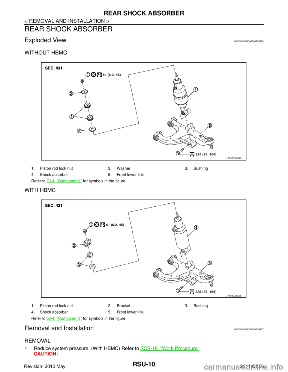
REAR SHOCK ABSORBER
REAR SHOCK ABSORBER
Exploded ViewINFOID:0000000006225666
WITHOUT HBMC
WITH HBMC
Removal and InstallationINFOID:0000000006225667
REMOVAL
1. Reduce system pressure. (With HBMC) Refer to SCS-18, "Work Procedure".
CAUTION:
1. Piston rod lock nut 2. Washer 3. Bushing
4. Shock absorber 5. Front lower link
Refer to GI-4, "
Components" for symbols in the figure.
JPEIB0246GB
1. Piston rod lock nut 2. Bracket 3. Bushing
4. Shock absorber 5. Front lower link
Refer to GI-4, "
Components" for symbols in the figure.
JPEIB0229GB
Revision: 2010 May2011 QX56