2011 INFINITI QX56 ABS
[x] Cancel search: ABSPage 3770 of 5598
MWI
SYSTEMMWI-27
< SYSTEM DESCRIPTION >
C
DE
F
G H
I
J
K L
M B A
O P
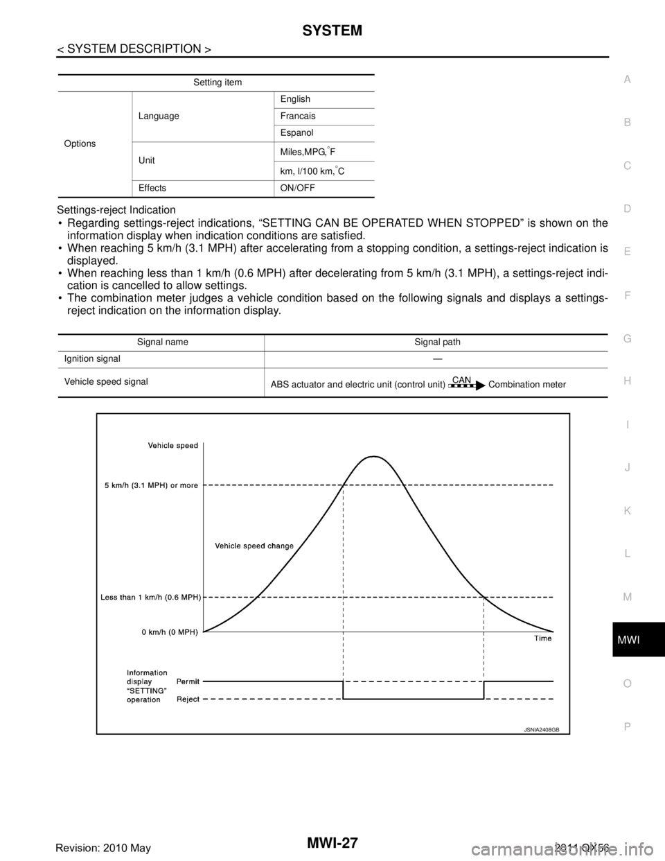
Settings-reject Indication
Regarding settings-reject indications, “SETTING CA
N BE OPERATED WHEN STOPPED” is shown on the
information display when indication conditions are satisfied.
When reaching 5 km/h (3.1 MPH) after accelerating from a stopping condition, a settings-reject indication is
displayed.
When reaching less than 1 km/h (0.6 MPH) after decelerat ing from 5 km/h (3.1 MPH), a settings-reject indi-
cation is cancelled to allow settings.
The combination meter judges a vehicle condition based on the following signals and displays a settings-
reject indication on the information display.
Setting item
Options Language
English
Francais
Espanol
Unit Miles,MPG,
°F
km, l/100 km,
°C
Effects ON/OFF
Signal name Signal path
Ignition signal —
Vehicle speed signal ABS actuator and electric unit (control unit) Combination meter
JSNIA2408GB
Revision: 2010 May2011 QX56
Page 3773 of 5598
MWI-30
< SYSTEM DESCRIPTION >
DIAGNOSIS SYSTEM (COMBINATION METER)
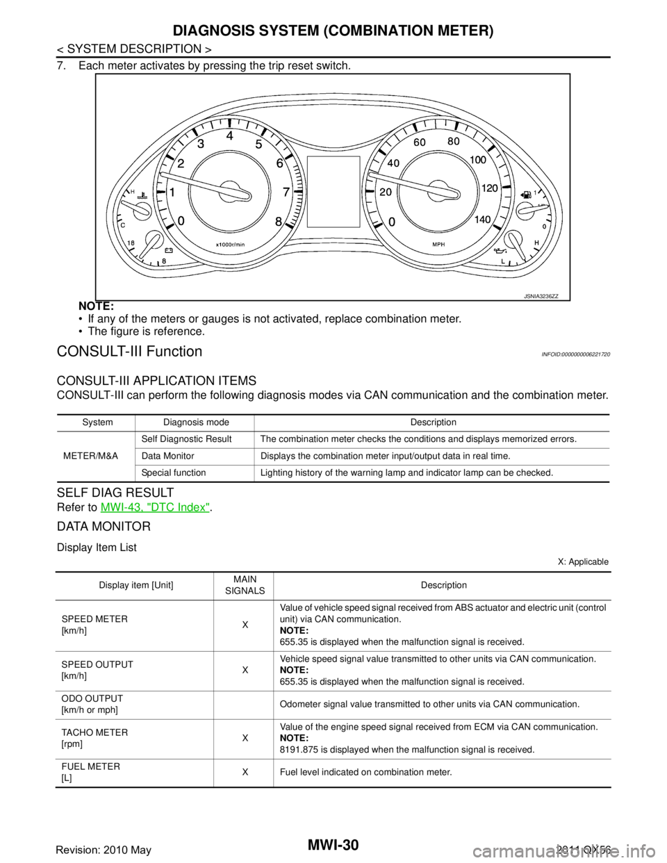
7. Each meter activates by pressing the trip reset switch.NOTE:
If any of the meters or gauges is not activated, replace combination meter.
The figure is reference.
CONSULT-III FunctionINFOID:0000000006221720
CONSULT-III APPLICATION ITEMS
CONSULT-III can perform the following diagnosis modes via CAN communication and the combination meter.
SELF DIAG RESULT
Refer to MWI-43, "DTC Index".
DATA MONITOR
Display Item List
X: Applicable
JSNIA3236ZZ
System Diagnosis mode Description
METER/M&A Self Diagnostic Result The combination meter checks the conditions and displays memorized errors.
Data Monitor Displays the combination meter input/output data in real time.
Special function Lighting history of the warning lamp and indicator lamp can be checked.
Display item [Unit]
MAIN
SIGNALS Description
SPEED METER
[km/h] XValue of vehicle speed
signal received from ABS actuator and el ectric unit (control
unit) via CAN communication.
NOTE:
655.35 is displayed when the malfunction signal is received.
SPEED OUTPUT
[km/h] XVehicle speed signal value transmitted to other units via CAN communication.
NOTE:
655.35 is displayed when the malfunction signal is received.
ODO OUTPUT
[km/h or mph] Odometer signal value transmitted to other units via CAN communication.
TACHO METER
[rpm] XValue of the engine speed signal received from ECM via CAN communication.
NOTE:
8191.875 is displayed when the malfunction signal is received.
FUEL METER
[L] X Fuel level indicated on combination meter.
Revision: 2010 May2011 QX56
Page 3774 of 5598
![INFINITI QX56 2011 Factory Service Manual
MWI
DIAGNOSIS SYSTEM (COMBINATION METER)
MWI-31
< SYSTEM DESCRIPTION >
C
D E
F
G H
I
J
K L
M B A
O P
W TEMP METER
[ ° C] XValue of engine coolant temperature signal is received from ECM via CAN com INFINITI QX56 2011 Factory Service Manual
MWI
DIAGNOSIS SYSTEM (COMBINATION METER)
MWI-31
< SYSTEM DESCRIPTION >
C
D E
F
G H
I
J
K L
M B A
O P
W TEMP METER
[ ° C] XValue of engine coolant temperature signal is received from ECM via CAN com](/manual-img/42/57033/w960_57033-3773.png)
MWI
DIAGNOSIS SYSTEM (COMBINATION METER)
MWI-31
< SYSTEM DESCRIPTION >
C
D E
F
G H
I
J
K L
M B A
O P
W TEMP METER
[ ° C] XValue of engine coolant temperature signal is received from ECM via CAN com-
munication.
NOTE:
215 is displayed when the malfunction signal is input.
ABS W/L
[On/Off] Status of ABS warning lamp detected fr
om ABS warning lamp signal is received
from ABS actuator and electric unit (control unit) via CAN communication.
VDC/TCS IND
[On/Off] Status of VDC OFF indicator lamp detected from VDC OFF indicator lamp signal
is received from ABS actuator
and electric unit (control unit) via CAN communica-
tion.
SLIP IND
[On/Off] Status of VDC warning lamp detected from VDC warning lamp signal received
from ABS actuator and electric unit (control unit) via CAN communication.
BRAKE W/L
[On/Off] Status of brake warning lamp detected from brake warning lamp signal is received
from ABS actuator and electric unit (control unit) via CAN communication.
NOTE:
Displays “Off” if the brake warning lamp is illuminated when the valve check starts,
the parking brake switch is turned ON or the brake fluid level switch is turned ON.
DOOR W/L
[On/Off] Status of door open warning detected from door switch signal received from BCM
via CAN communication.
HI-BEAM IND
[On/Off] Status of high beam indicator lamp detected from high beam request signal is re-
ceived from BCM via CAN communication.
TURN IND
[On/Off] Status of turn indicator lamp detected from turn indicator signal is received from
BCM via CAN communication.
FR FOG IND
[Off] This item is displayed, but cannot be monitored.
RR FOG IND
[Off] This item is displayed, but cannot be monitored.
LIGHT IND
[On/Off] Status of light indicator lamp detected from position light request signal is received
from BCM via CAN communication.
OIL W/L
[On/Off] Status of oil pressure warning lamp detected from oil pressure switch signal is re-
ceived from BCM via CAN communication.
MIL
[On/Off] Status of malfunction indicator lamp detected from malfunctioning indicator lamp
signal is received from ECM via CAN communication.
GLOW IND
[Off] This item is displayed, but cannot be monitored.
CRUISE IND
[On/Off] Status of CRUISE indicator detected from ASCD status signal is received from
ECM via CAN communicat ion. (ASCD models)
Status of CRUISE indicator de tected from meter display signal is received from
ADAS control unit via CAN communication. (ICC models)
SET IND
[On/Off] Status of SET indicator detected from meter display signal is received from ADAS
control unit via CAN communication.
CRUISE W/L
[On/Off] Status of CRUISE warning lamp
judged from ICC warning lamp signal received
from ADAS control unit with CAN communication line.
BA W/L
[On/Off] Status of IBA OFF indicator lamp judged from IBA OFF indicator lamp signal re-
ceived from ADAS control unit with CAN communication line.
ATC/T-AMT W/L
[On/Off] Status of A/T CHECK warning lamp judged
from A/T CHECK indicator lamp signal
received from TCM with CAN communication line.
ATF TEMP W/L
[Off] This item is displayed, but cannot be monitored.
4WD W/L
[On/Off] Status of 4WD warning lamp judged from 4WD warning lamp signal received from
4WD control unit with
CAN communication line.
FUEL W/L
[On/Off] Low-fuel warning lamp status detected by the identified fuel level.
WASHER W/L
[On/Off] Status of low washer fluid warning judged from washer level switch input to com-
bination meter.
Display item [Unit]
MAIN
SIGNALS Description
Revision: 2010 May2011 QX56
Page 3777 of 5598

MWI-34
< SYSTEM DESCRIPTION >
DIAGNOSIS SYSTEM (COMBINATION METER)
Display item Description
ABS W/L Lighting history of ABS warning lamp.
VDC/TCS IND Lighting history of VDC OFF indicator lamp.
SLIP IND Lighting history of VDC warning lamp.
BRAKE W/L Lighting history of brake warning lamp.
DOOR W/L Lighting history of door open warning.
TRUNK/GLAS-H This item is displa yed, but cannot be monitored.
OIL W/L Lighting history of oil pressure warning lamp.
C-ENG W/L Lighting history of malfunction indicator lamp.
C-ENG2 W/L This item is displayed, but cannot be monitored.
CRUISE IND Lighting history of CRUISE indicator lamp.
SET IND Lighting history of SET indicator lamp.
CRUISE W/L Lighting history of CRUISE warning lamp.
BA W/L Lighting history of IBA OFF indicator lamp.
O/D OFF IND This item is displayed, but cannot be monitored.
ATC/T-AMT W/L Lighting history of A/T CHECK warning lamp.
ATF TEMP W/L This item is displayed, but cannot be monitored.
CVT IND This item is displayed, but cannot be monitored.
SPORT IND This item is displayed, but cannot be monitored.
4WD W/L Lighting history of 4WD warning lamp.
FUEL W/L Lighting history of low fuel level warning.
WASHER W/L Lighting history of low washer fluid warning.
AIR PRES W/L Lighting history of low tire pressure warning lamp.
KEY G/Y W/L Lighting history of KEY warning lamp.
KEY R W/L This item is displaye d, but cannot be monitored.
KEY KNOB W/L This item is displa yed, but cannot be monitored.
EPS W/L This item is displayed, but cannot be monitored.
e-4WD This item is displayed, but cannot be monitored.
AFS OFF IND This item is displayed, but cannot be monitored.
4WAS/RAS W/L This item is displayed, but cannot be monitored.
HDC W/L This item is displayed, but cannot be monitored.
SYS FAIL W/L This item is displa yed, but cannot be monitored.
SFT POSI W/L This item is displayed, but cannot be monitored.
HV BAT W/L This item is displayed, but cannot be monitored.
HEV BRAKE W/L This item is displayed, but cannot be monitored.
SFT OPER W/L This item is displayed, but cannot be monitored.
LANE W/L Lighting history of lane departure warning lamp.
CHAGE W/L This item is displayed, but cannot be monitored.
OIL LEV LOW This item is displayed, but cannot be monitored.
DPF W/L This item is displayed, but cannot be monitored.
TRAILER IND This item is displayed, but cannot be monitored.
RUN FLAT W/L This item is displa yed, but cannot be monitored.
E-SUS W/L This item is displayed, but cannot be monitored.
LAUNCH CNT W/L This item is displayed, but cannot be monitored.
BRAKE PAD W/L This item is displa yed, but cannot be monitored.
Revision: 2010 May2011 QX56
Page 3778 of 5598
MWI
COMBINATION METERMWI-35
< ECU DIAGNOSIS INFORMATION >
C
DE
F
G H
I
J
K L
M B A
O P
ECU DIAGNOSIS INFORMATION
COMBINATION METER
Reference ValueINFOID:0000000006221721
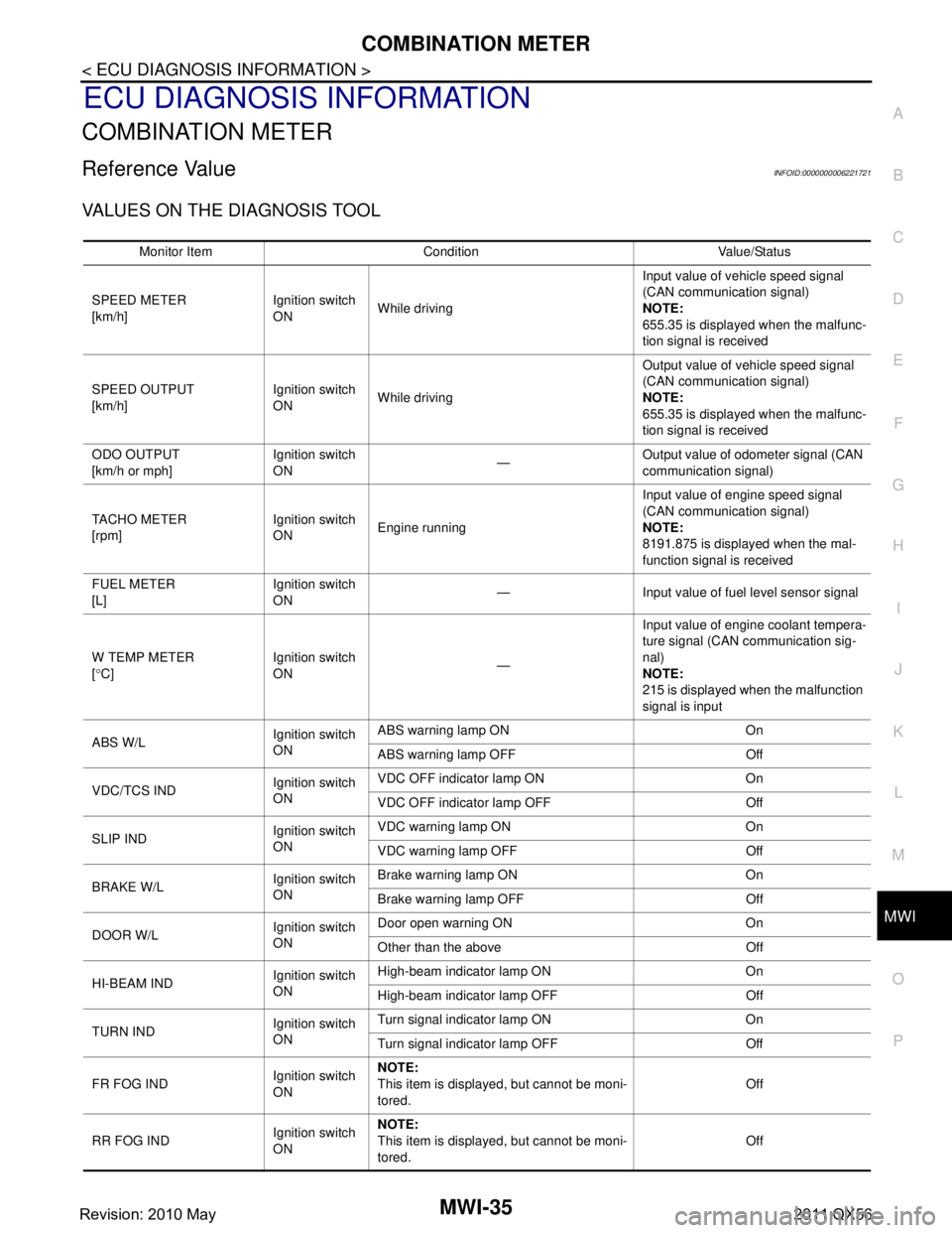
VALUES ON THE DIAGNOSIS TOOL
Monitor Item Condition Value/Status
SPEED METER
[km/h] Ignition switch
ON
While driving Input value of vehicle speed signal
(CAN communication signal)
NOTE:
655.35 is displayed when the malfunc-
tion signal is received
SPEED OUTPUT
[km/h] Ignition switch
ON
While driving Output value of vehicle speed signal
(CAN communication signal)
NOTE:
655.35 is displayed when the malfunc-
tion signal is received
ODO OUTPUT
[km/h or mph] Ignition switch
ON
—Output value of odometer signal (CAN
communication signal)
TACHO METER
[rpm] Ignition switch
ON
Engine running Input value of engine speed signal
(CAN communication signal)
NOTE:
8191.875 is displayed when the mal-
function signal is received
FUEL METER
[L] Ignition switch
ON
— Input value of fuel level sensor signal
W TEMP METER
[ ° C] Ignition switch
ON
—Input value of engine coolant tempera-
ture signal (CAN communication sig-
nal)
NOTE:
215 is displayed when the malfunction
signal is input
ABS W/L Ignition switch
ONABS warning lamp ON On
ABS warning lamp OFF Off
VDC/TCS IND Ignition switch
ONVDC OFF indicator lamp ON On
VDC OFF indicator lamp OFF Off
SLIP IND Ignition switch
ONVDC warning lamp ON On
VDC warning lamp OFF Off
BRAKE W/L Ignition switch
ONBrake warning lamp ON On
Brake warning lamp OFF Off
DOOR W/L Ignition switch
ONDoor open warning ON On
Other than the above Off
HI-BEAM IND Ignition switch
ONHigh-beam indicator lamp ON On
High-beam indicator lamp OFF Off
TURN IND Ignition switch
ONTurn signal indicator lamp ON On
Turn signal indicator lamp OFF Off
FR FOG IND Ignition switch
ONNOTE:
This item is displayed, but cannot be moni-
tored.
Off
RR FOG IND Ignition switch
ONNOTE:
This item is displayed, but cannot be moni-
tored.
Off
Revision: 2010 May2011 QX56
Page 3786 of 5598

MWI
COMBINATION METERMWI-43
< ECU DIAGNOSIS INFORMATION >
C
DE
F
G H
I
J
K L
M B A
O P
DTC IndexINFOID:0000000006221723
Warning lamp/indicator lamp ABS warning lamp
The lamp turns ON by suspending communication.
VDC warning lamp
Brake warning lamp
IBA OFF indicator lamp
4WD warning lamp
Malfunction indicator lamp
VDC OFF indicator lamp
CRUISE warning lamp
Low tire pressure warning lamp The lamp blinking caused by suspending communication.
High beam indicator lamp
The lamp turns OFF by suspending communication.
Turn signal indicator lamp
Tail lamp indicator lamp
A/T CHECK indicator lamp
Key warning lamp
AT P w a r n i n g l a m p
Lane departure warning lamp
LDP ON indicator lamp
CRUISE indicator lamp
Oil pressure warning lamp
SNOW mode indicator lamp
TOW mode indicator lamp
CK SUSP indicator lamp
BSW indicator lamp
Function Specifications
Display contents of CONSULT-III Diagnostic item is detected when... Refer to
CAN COMM CIRCUIT
[U1000] When combination meter is not transmitting or receiving CAN communication signal
for 2 seconds or more. MWI-59,
"Diagnosis
Procedure"
CONTROL UNIT (CAN)
[U1010]
When detecting error during the initial diagnosis of the CAN controller of combina-
tion meter. MWI-60, "Diagnosis
Procedure"
VEHICLE SPEED
[B2205]
The abnormal vehicle speed signal is input from the ABS actuator and electric unit
(control unit) for
2 seconds or more. MWI-61, "Diagnosis
Procedure"
ENGINE SPEED
[B2267]
If ECM continuously transmits abnormal engine speed signals for 2 seconds or
more. MWI-62, "Diagnosis
Procedure"
WATER TEMP
[B2268]
If ECM continuously transmits abnormal engine coolant temperature signals for 60
seconds or more. MWI-63, "Diagnosis
Procedure"
Revision: 2010 May2011 QX56
Page 3804 of 5598
MWI
B2205 VEHICLE SPEEDMWI-61
< DTC/CIRCUIT DIAGNOSIS >
C
DE
F
G H
I
J
K L
M B A
O P
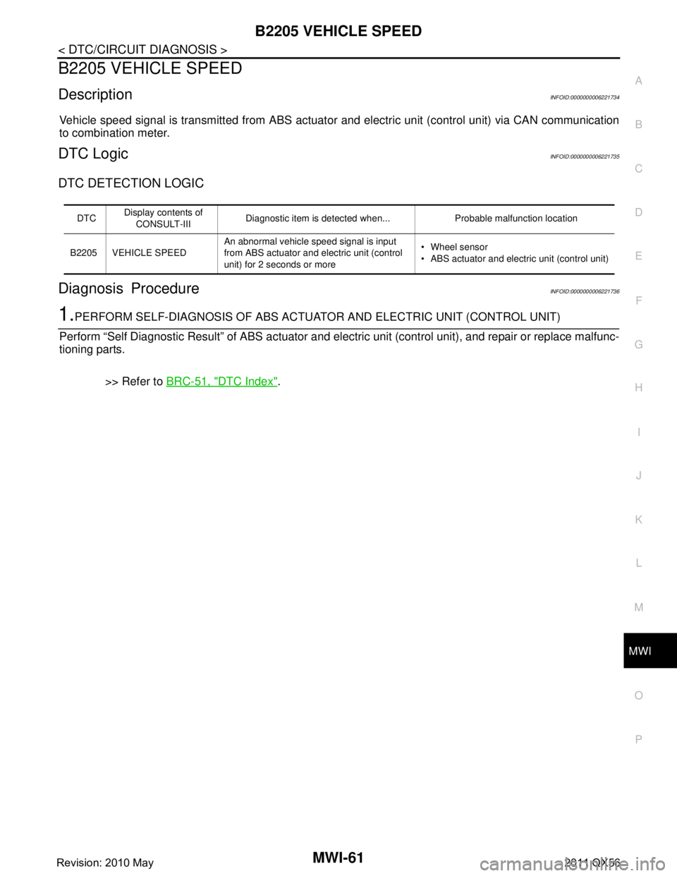
B2205 VEHICLE SPEED
DescriptionINFOID:0000000006221734
Vehicle speed signal is transmitted from ABS actuator and electric unit (control unit) via CAN communication
to combination meter.
DTC LogicINFOID:0000000006221735
DTC DETECTION LOGIC
Diagnosis ProcedureINFOID:0000000006221736
1.PERFORM SELF-DIAGNOSIS OF ABS ACTUAT OR AND ELECTRIC UNIT (CONTROL UNIT)
Perform “Self Diagnostic Result” of ABS actuator and electric unit (control unit), and repair or replace malfunc-
tioning parts.
>> Refer to BRC-51, "
DTC Index".
DTCDisplay contents of
CONSULT-III Diagnostic item is detected when... Probable malfunction location
B2205 VEHICLE SPEED An abnormal vehicle speed signal is input
from ABS actuator and electric unit (control
unit) for 2 seconds or more Wheel sensor
ABS actuator and electric
unit (control unit)
Revision: 2010 May2011 QX56
Page 3828 of 5598
MWI
COMBINATION METERMWI-85
< REMOVAL AND INSTALLATION >
C
DE
F
G H
I
J
K L
M B A
O P
REMOVAL AND INSTALLATION
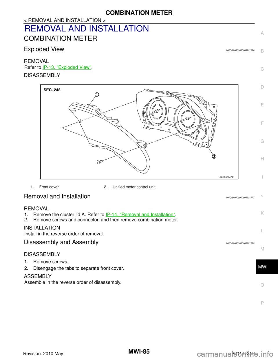
COMBINATION METER
Exploded ViewINFOID:0000000006221776
REMOVAL
Refer to IP-13, "Exploded View".
DISASSEMBLY
Removal and InstallationINFOID:0000000006221777
REMOVAL
1. Remove the cluster lid A. Refer to IP-14, "Removal and Installation".
2. Remove screws and connector, and then remove combination meter.
INSTALLATION
Install in the reverse order of removal.
Disassembly and AssemblyINFOID:0000000006221778
DISASSEMBLY
1. Remove screws.
2. Disengage the tabs to separate front cover.
ASSEMBLY
Assemble in the reverse order of disassembly.
1. Front cover 2. Unified meter control unit
JSNIA3014ZZ
Revision: 2010 May2011 QX56