2011 INFINITI QX56 wheel torque
[x] Cancel search: wheel torquePage 3696 of 5598
MA-26
< PERIODIC MAINTENANCE >
CHASSIS MAINTENANCE
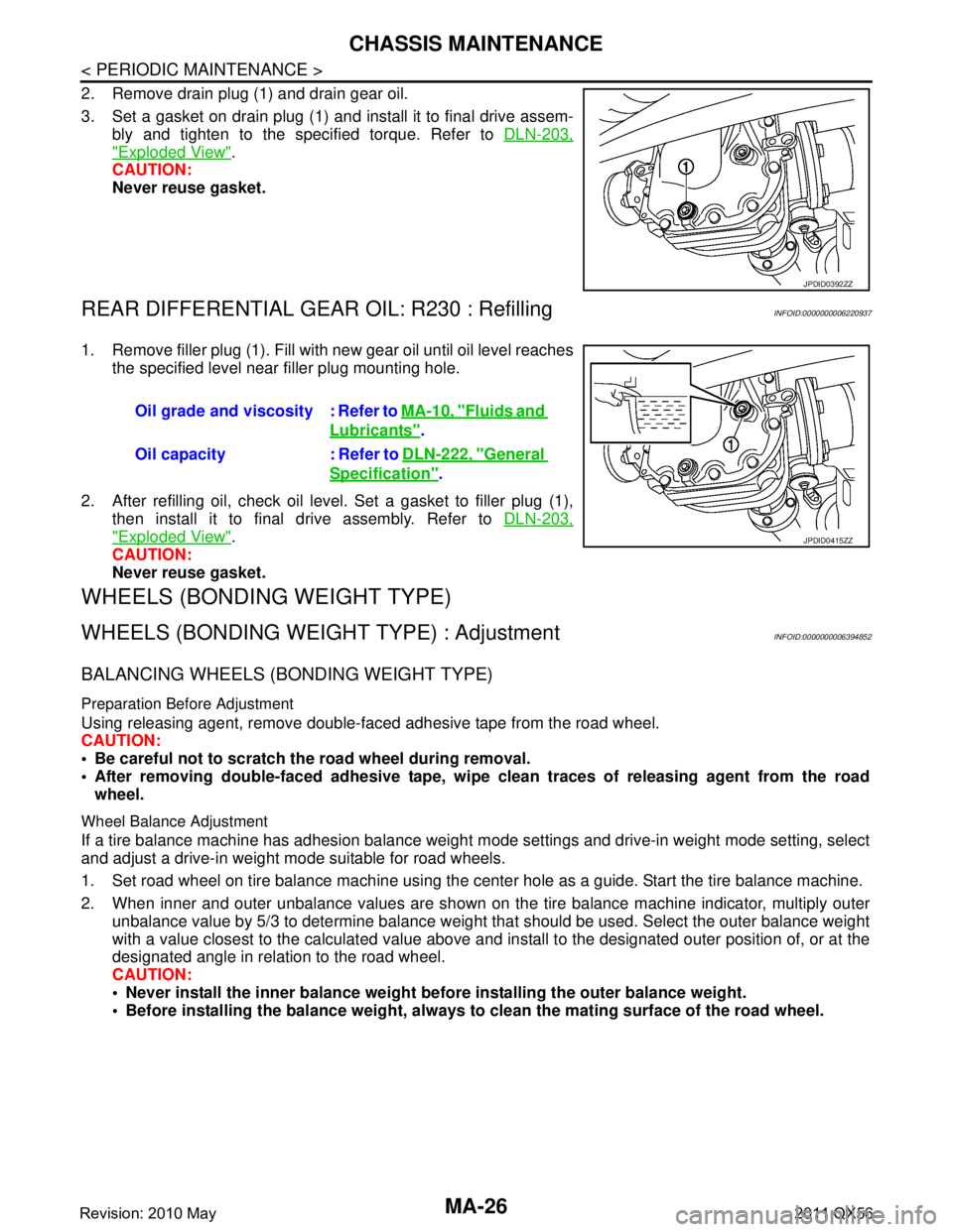
2. Remove drain plug (1) and drain gear oil.
3. Set a gasket on drain plug (1) and install it to final drive assem-bly and tighten to the specified torque. Refer to DLN-203,
"Exploded View".
CAUTION:
Never reuse gasket.
REAR DIFFERENTIAL GEAR OIL: R230 : RefillingINFOID:0000000006220937
1. Remove filler plug (1). Fill with new gear oil until oil level reaches
the specified level near filler plug mounting hole.
2. After refilling oil, check oil level. Set a gasket to filler plug (1), then install it to final drive assembly. Refer to DLN-203,
"Exploded View".
CAUTION:
Never reuse gasket.
WHEELS (BONDING WEIGHT TYPE)
WHEELS (BONDING WEIG HT TYPE) : AdjustmentINFOID:0000000006394852
BALANCING WHEELS (BONDING WEIGHT TYPE)
Preparation Before Adjustment
Using releasing agent, remove double-faced adhesive tape from the road wheel.
CAUTION:
Be careful not to scratch th e road wheel during removal.
After removing double-faced adhesive tape, wi pe clean traces of releasing agent from the road
wheel.
Wheel Balance Adjustment
If a tire balance machine has adhesion balance weight m ode settings and drive-in weight mode setting, select
and adjust a drive-in weight mode suitable for road wheels.
1. Set road wheel on tire balance machine using the center hole as a guide. Start the tire balance machine.
2. When inner and outer unbalance values are shown on the tire balance machine indicator, multiply outer unbalance value by 5/3 to determine balance weight t hat should be used. Select the outer balance weight
with a value closest to the calculated value above and in stall to the designated outer position of, or at the
designated angle in relation to the road wheel.
CAUTION:
Never install the inner balance weight be fore installing the outer balance weight.
Before installing the balance weight, always to clean the mating surface of the road wheel.
JPDID0392ZZ
Oil grade and viscosity : Refer to MA-10, "Fluids and
Lubricants".
Oil capacity : Refer to DLN-222, "
General
Specification".
JPDID0415ZZ
Revision: 2010 May2011 QX56
Page 4205 of 5598
REAR WHEEL HUB AND HOUSINGRAX-9
< REMOVAL AND INSTALLATION >
CEF
G H
I
J
K L
M A
B
RAX
N
O P
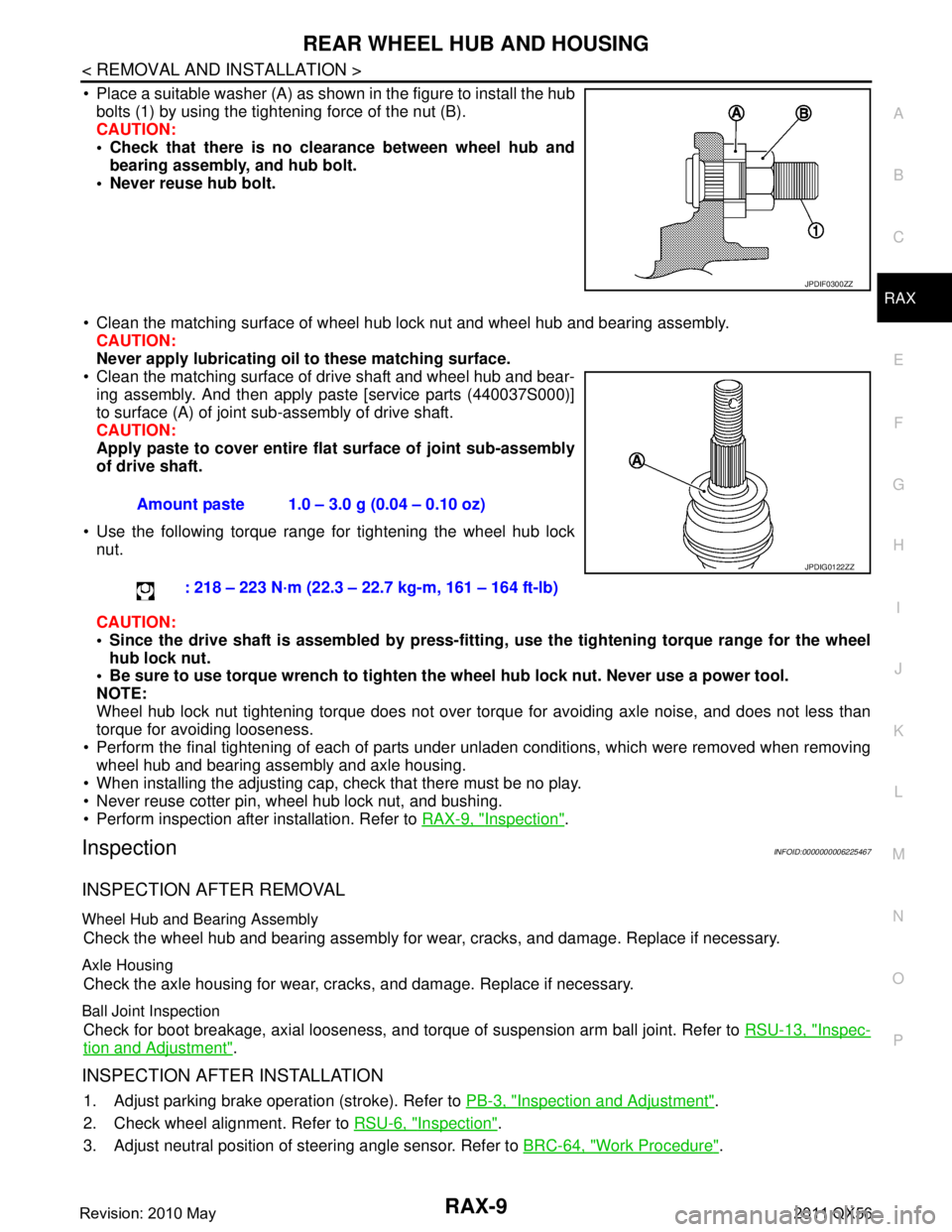
Place a suitable washer (A) as shown in the figure to install the hub bolts (1) by using the tightening force of the nut (B).
CAUTION:
Check that there is no cl earance between wheel hub and
bearing assembly, and hub bolt.
Never reuse hub bolt.
Clean the matching surface of wheel hub lock nut and wheel hub and bearing assembly. CAUTION:
Never apply lubricating oi l to these matching surface.
Clean the matching surface of drive shaft and wheel hub and bear-
ing assembly. And then apply paste [service parts (440037S000)]
to surface (A) of joint sub-assembly of drive shaft.
CAUTION:
Apply paste to cover entire fl at surface of joint sub-assembly
of drive shaft.
Use the following torque range for tightening the wheel hub lock nut.
CAUTION:
Since the drive shaft is assembled by press-fitting , use the tightening torque range for the wheel
hub lock nut.
Be sure to use torque wrench to tighten th e wheel hub lock nut. Never use a power tool.
NOTE:
Wheel hub lock nut tightening torque does not over tor que for avoiding axle noise, and does not less than
torque for avoiding looseness.
Perform the final tightening of each of parts under unladen conditions, which were removed when removing wheel hub and bearing assembly and axle housing.
When installing the adjusting cap, check that there must be no play.
Never reuse cotter pin, wheel hub lock nut, and bushing.
Perform inspection after installation. Refer to RAX-9, "
Inspection".
InspectionINFOID:0000000006225467
INSPECTION AFTER REMOVAL
Wheel Hub and Bearing Assembly
Check the wheel hub and bearing assembly for wear, cracks, and damage. Replace if necessary.
Axle Housing
Check the axle housing for wear, cracks, and damage. Replace if necessary.
Ball Joint Inspection
Check for boot breakage, axial looseness, and torque of suspension arm ball joint. Refer to RSU-13, "Inspec-
tion and Adjustment".
INSPECTION AFTER INSTALLATION
1. Adjust parking brake operation (stroke). Refer to PB-3, "Inspection and Adjustment".
2. Check wheel alignment. Refer to RSU-6, "
Inspection".
3. Adjust neutral position of steering angle sensor. Refer to BRC-64, "
Work Procedure".
JPDIF0300ZZ
Amount paste 1.0 – 3.0 g (0.04 – 0.10 oz)
: 218 – 223 N·m (22.3 – 22.7 kg-m, 161 – 164 ft-lb)
JPDIG0122ZZ
Revision: 2010 May2011 QX56
Page 4208 of 5598
RAX-12
< REMOVAL AND INSTALLATION >
REAR DRIVE SHAFT
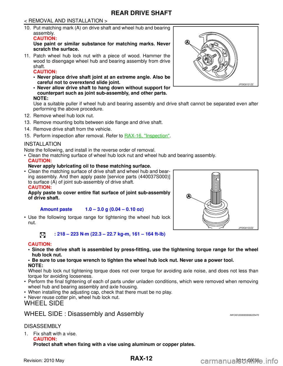
10. Put matching mark (A) on drive shaft and wheel hub and bearingassembly.
CAUTION:
Use paint or similar substance for matching marks. Never
scratch the surface.
11. Patch wheel hub lock nut with a piece of wood. Hammer the wood to disengage wheel hub and bearing assembly from drive
shaft.
CAUTION:
Never place drive shaft joint at an extreme angle. Also becareful not to over extend slide joint.
Never allow drive shaft to ha ng down without support for
counterpart such as joint sub-assembly, and other parts.
NOTE:
Use a suitable puller if wheel hub and bearing assembly and drive shaft cannot be separated even after
performing the above procedure.
12. Remove wheel hub lock nut.
13. Remove mounting bolts between side flange and drive shaft.
14. Remove drive shaft from the vehicle.
15. Perform inspection after removal. Refer to RAX-16, "
Inspection".
INSTALLATION
Note the following, and install in the reverse order of removal.
Clean the matching surface of wheel hub lock nut and wheel hub and bearing assembly.
CAUTION:
Never apply lubricating oi l to these matching surface.
Clean the matching surface of drive shaft and wheel hub and bear- ing assembly. And then apply paste [service parts (440037S000)]
to surface (A) of joint sub-assembly of drive shaft.
CAUTION:
Apply paste to cover entire fl at surface of joint sub-assembly
of drive shaft.
Use the following torque range for tightening the wheel hub lock nut.
CAUTION:
Since the drive shaft is assembled by press-fittin g, use the tightening torque range for the wheel
hub lock nut.
Be sure to use torque wrench to tighten th e wheel hub lock nut. Never use a power tool.
NOTE:
Wheel hub lock nut tightening torque does not over torque for avoiding axle noise, and does not less than
torque for avoiding looseness.
Perform the final tightening of each of parts under unladen conditions, which were removed when removing
wheel hub and bearing assembly and axle housing.
When installing the adjusting cap, check that there must be no play.
Never reuse cotter pin, wheel hub lock nut.
WHEEL SIDE
WHEEL SIDE : Disassembly and AssemblyINFOID:0000000006225470
DISASSEMBLY
1. Fix shaft with a vise. CAUTION:
Protect shaft when fixing with a vi se using aluminum or copper plates.
JPDIG0121ZZ
Amount paste 1.0 – 3.0 g (0.04 – 0.10 oz)
: 218 – 223 N·m (22.3 – 22.7 kg-m, 161 – 164 ft-lb)
JPDIG0122ZZ
Revision: 2010 May2011 QX56
Page 4262 of 5598
WHEEL ALIGNMENTRSU-7
< PERIODIC MAINTENANCE >
C
DF
G H
I
J
K L
M A
B
RSU
N
O P
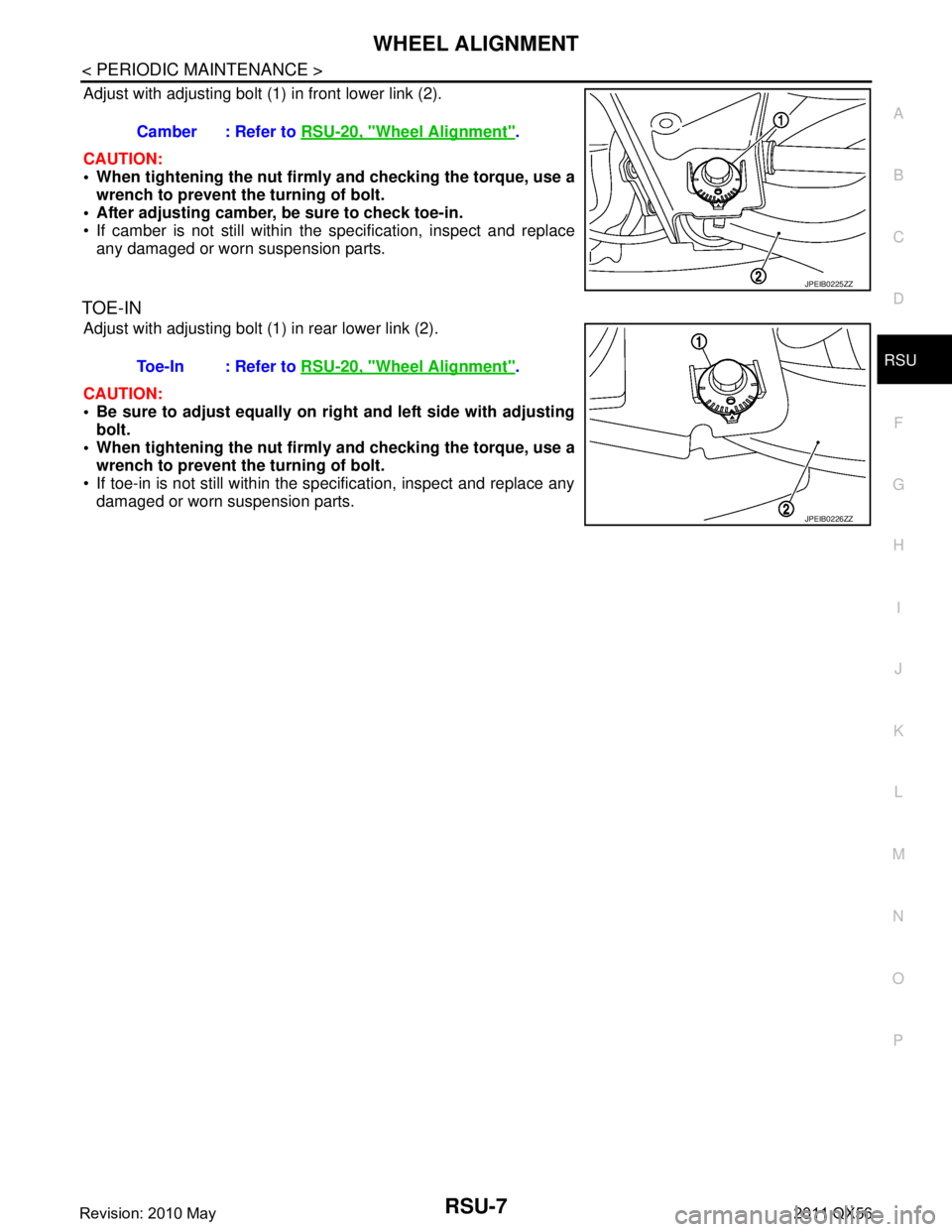
Adjust with adjusting bolt (1) in front lower link (2).
CAUTION:
When tightening the nut firml y and checking the torque, use a
wrench to prevent the turning of bolt.
After adjusting camber, be sure to check toe-in.
If camber is not still within the specification, inspect and replace
any damaged or worn suspension parts.
TOE-IN
Adjust with adjusting bolt (1) in rear lower link (2).
CAUTION:
Be sure to adjust equally on ri ght and left side with adjusting
bolt.
When tightening the nut firml y and checking the torque, use a
wrench to prevent the turning of bolt.
If toe-in is not still within the specification, inspect and replace any damaged or worn suspension parts. Camber : Refer to
RSU-20, "
Wheel Alignment".
JPEIB0225ZZ
Toe-In : Refer to RSU-20, "Wheel Alignment".
JPEIB0226ZZ
Revision: 2010 May2011 QX56
Page 4269 of 5598
RSU-14
< REMOVAL AND INSTALLATION >
SUSPENSION ARM
1. Move the ball joint at least ten times by hand to check for smooth movement.
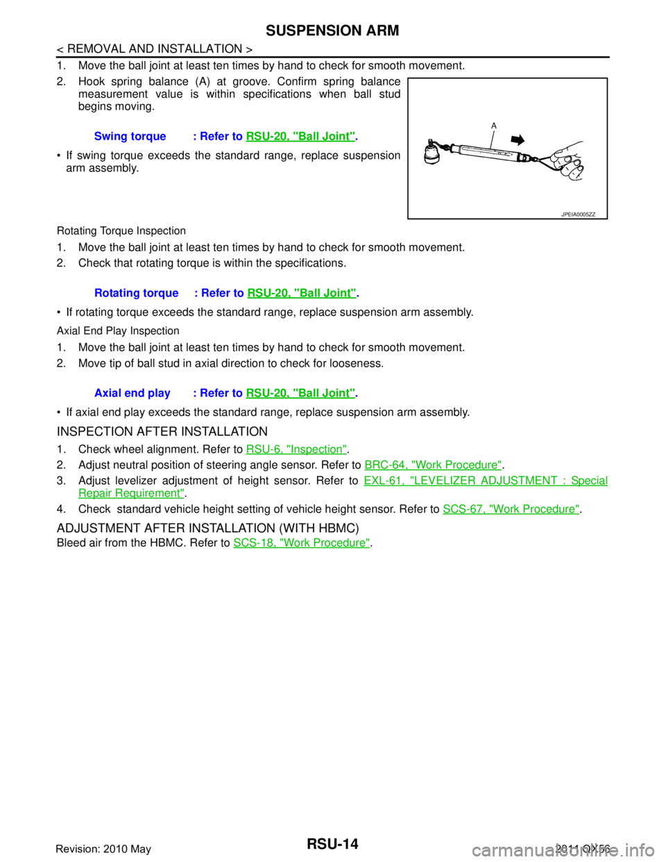
2. Hook spring balance (A) at groove. Confirm spring balancemeasurement value is within specifications when ball stud
begins moving.
If swing torque exceeds the standard range, replace suspension arm assembly.
Rotating Torque Inspection
1. Move the ball joint at least ten times by hand to check for smooth movement.
2. Check that rotating torque is within the specifications.
If rotating torque exceeds the standard range, replace suspension arm assembly.
Axial End Play Inspection
1. Move the ball joint at least ten times by hand to check for smooth movement.
2. Move tip of ball stud in axial direction to check for looseness.
If axial end play exceeds the standard r ange, replace suspension arm assembly.
INSPECTION AFTER INSTALLATION
1. Check wheel alignment. Refer to RSU-6, "Inspection".
2. Adjust neutral position of steering angle sensor. Refer to BRC-64, "
Work Procedure".
3. Adjust levelizer adjustment of height sensor. Refer to EXL-61, "
LEVELIZER ADJUSTMENT : Special
Repair Requirement".
4. Check standard vehicle height setting of vehicle height sensor. Refer to SCS-67, "
Work Procedure".
ADJUSTMENT AFTER INSTALLATION (WITH HBMC)
Bleed air from the HBMC. Refer to SCS-18, "Work Procedure".
Swing torque : Refer to
RSU-20, "
Ball Joint".
JPEIA0005ZZ
Rotating torque : Refer to RSU-20, "Ball Joint".
Axial end play : Refer to RSU-20, "
Ball Joint".
Revision: 2010 May2011 QX56
Page 4271 of 5598
RSU-16
< REMOVAL AND INSTALLATION >
FRONT LOWER LINK
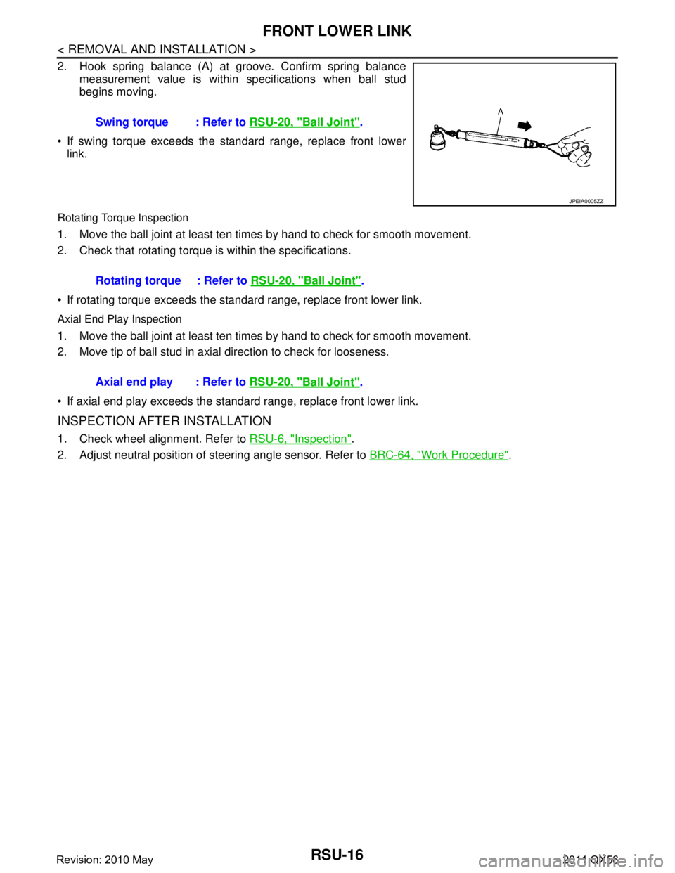
2. Hook spring balance (A) at groove. Confirm spring balancemeasurement value is within specifications when ball stud
begins moving.
If swing torque exceeds the standard range, replace front lower link.
Rotating Torque Inspection
1. Move the ball joint at least ten times by hand to check for smooth movement.
2. Check that rotating torque is within the specifications.
If rotating torque exceeds the standar d range, replace front lower link.
Axial End Play Inspection
1. Move the ball joint at least ten times by hand to check for smooth movement.
2. Move tip of ball stud in axial direction to check for looseness.
If axial end play exceeds the standard range, replace front lower link.
INSPECTION AFTER INSTALLATION
1. Check wheel alignment. Refer to RSU-6, "Inspection".
2. Adjust neutral position of steering angle sensor. Refer to BRC-64, "
Work Procedure".
Swing torque : Refer to
RSU-20, "
Ball Joint".
JPEIA0005ZZ
Rotating torque : Refer to RSU-20, "Ball Joint".
Axial end play : Refer to RSU-20, "
Ball Joint".
Revision: 2010 May2011 QX56
Page 4275 of 5598
RSU-20
< SERVICE DATA AND SPECIFICATIONS (SDS)
SERVICE DATA AND SPECIFICATIONS (SDS)
SERVICE DATA AND SPECIFICATIONS (SDS)
SERVICE DATA AND SPECIFICATIONS (SDS)
Wheel AlignmentINFOID:0000000006225679
Measure value under unladen* conditions.
*: Fuel, engine coolant and lubricant are full. Spare tire, jack, hand tools and mats are in designated positions.
Ball JointINFOID:0000000006225680
Wheel HeightINFOID:0000000006225681
Measure value under unladen* conditions.
*: Fuel, engine coolant and lubricant are full. Spare tire, jack, hand tools and mats are in designated positions.Item Standard
Camber
Degree minute (Decimal degree) Minimum –1
° 00 ′ (–1.00 °)
Nominal –0 ° 30 ′ (–0.50 °)
Maximum 0 ° 00 ′ (0.00 °)
Left and right difference 0 ° 45 ′ (0.75 °) or less
To e - i n Total toe-in
Distance
Minimum 0 mm (0 in)
Nominal In 3.4 mm (0.134 in)
Maximum In 6.8 mm (0.268 in)
Toe angle (left wheel or right wheel)
Degree minute (Decimal degree) Minimum 0
° 00 ′ (0.00 °)
Nominal In 0 ° 07 ′ (0.12 °)
Maximum In 0 ° 14 ′ (0.23 °)
Item Standard
Swing torque 0.5 – 6.4 N·m (0.06 – 0.65 kg-m, 5 – 56 in-lb)
Measurement on spring balance (groove position) Suspension arm 11.4 – 145.4 N (1.17 – 14.83 kg, 2.57 – 32.68 lb)
Front lower link 11.0 – 140.6 N (1.13 – 14.34 kg, 2.48 – 31.60 lb)
Rotating torque 0.5 – 6.4 N·m (0.06 – 0.65 kg-m, 5 – 56 in-lb)
Axial end play 0 mm (0 in)
Item Standard
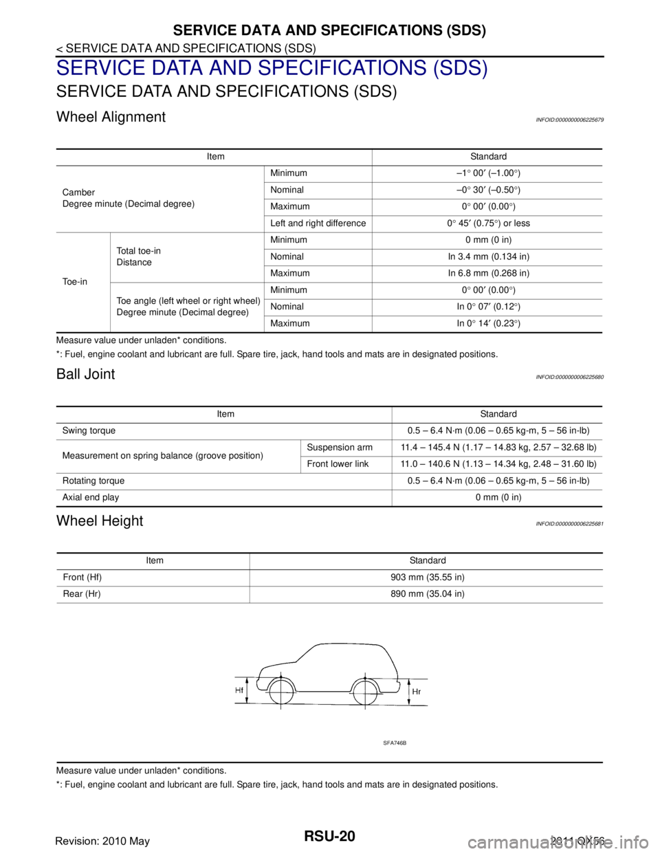
Front (Hf) 903 mm (35.55 in)
Rear (Hr) 890 mm (35.04 in)
SFA746B
Revision: 2010 May2011 QX56
Page 4389 of 5598
![INFINITI QX56 2011 Factory Service Manual
DIFFERENCE IN APPEARANCESCS-29
< SYMPTOM DIAGNOSIS > [HBMC]
C
D
F
G H
I
J
K L
M A
B
SCS
N
O P
SYMPTOM DIAGNOSIS
DIFFERENCE IN APPEARANCE
DescriptionINFOID:0000000006256016
While the vehicle is stoppe INFINITI QX56 2011 Factory Service Manual
DIFFERENCE IN APPEARANCESCS-29
< SYMPTOM DIAGNOSIS > [HBMC]
C
D
F
G H
I
J
K L
M A
B
SCS
N
O P
SYMPTOM DIAGNOSIS
DIFFERENCE IN APPEARANCE
DescriptionINFOID:0000000006256016
While the vehicle is stoppe](/manual-img/42/57033/w960_57033-4388.png)
DIFFERENCE IN APPEARANCESCS-29
< SYMPTOM DIAGNOSIS > [HBMC]
C
D
F
G H
I
J
K L
M A
B
SCS
N
O P
SYMPTOM DIAGNOSIS
DIFFERENCE IN APPEARANCE
DescriptionINFOID:0000000006256016
While the vehicle is stopped, the difference of vehicle height of right side and left side (between wheel center
and wheel arch) is 25 mm (0.98 in) or more.
Inspection ProcedureINFOID:0000000006256017
1.CHECK APPEARANCE
1. Visually check that the exterior parts (e.g. suspension spring) have no malfunctions.
2. Visually check tube and pipe for crush or oil leakage.
Is the check result normal?
YES >> GO TO 2.
NO >> Repair or replace damaged parts.
2.CHECK CLOGGING OF ORIFICE IN PPMU
1. Install an oil pressure gauge (SST: KV40108000) (A) to oil injec- tion jack.
CAUTION:
Clean surrounding areas of oi l injection jack using steam
before starting oper ation, since there may be mud on it.
Clean oil pressure gauge (special service tool:
KV40108000) jack with steam before use.
Jack must be securely inserted until a click sound can be heard.
Pressure reducing valve (B) of the oil pressure gauge
must be closed.
2. Loosen needle valves A and C of PPMU by approximately 2 rotations for check changes in vehicle height.
CAUTION:
Never loosen the needle valve more than required.
3. Tighten needle valve A and C of PPMU to the specified torque after the inspection.
Does the vehicle height change 10 mm (0.39 in) or more?
YES >> For detailed inspection of clogging of orifice in PPMU, refer to SCS-27, "
Work Procedure".
NO >> INSPECTION END
JSEIA0186ZZ
Tightening torque : 8.3 N· m (0.85 kg-m, 73 in-lb)
JSEIA0187ZZ
Revision: 2010 May2011 QX56