Page 1649 of 5598
B2627 OUTSIDE ANTENNADLK-113
< DTC/CIRCUIT DIAGNOSIS >
C
DE
F
G H
I
J
L
M A
B
DLK
N
O P
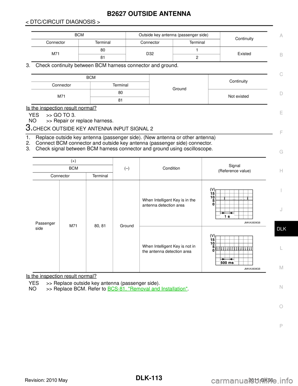
3. Check continuity between BCM harness connector and ground.
Is the inspection result normal?
YES >> GO TO 3.
NO >> Repair or replace harness.
3.CHECK OUTSIDE KEY ANTENNA INPUT SIGNAL 2
1. Replace outside key antenna (passenger side). (New antenna or other antenna)
2. Connect BCM connector and outside key antenna (passenger side) connector.
3. Check signal between BCM harness connector and ground using oscilloscope.
Is the inspection result normal?
YES >> Replace outside key antenna (passenger side).
NO >> Replace BCM. Refer to BCS-81, "
Removal and Installation".
BCM Outside key antenna (passenger side)
Continuity
Connector Terminal Connector Terminal
M71 80
D32 1
Existed
81 2
BCM GroundContinuity
Connector Terminal
M71 80
Not existed
81
(+)
(–) Condition Signal
(Reference value)
BCM
Connector Terminal
Passenger
side M71 80, 81 Ground When Intelligent Key is in the
antenna detection area
When Intelligent Key is not in
the antenna detection area
JMKIA3839GB
JMKIA3838GB
Revision: 2010 May2011 QX56
Page 1651 of 5598
B2628 OUTSIDE ANTENNADLK-115
< DTC/CIRCUIT DIAGNOSIS >
C
DE
F
G H
I
J
L
M A
B
DLK
N
O P
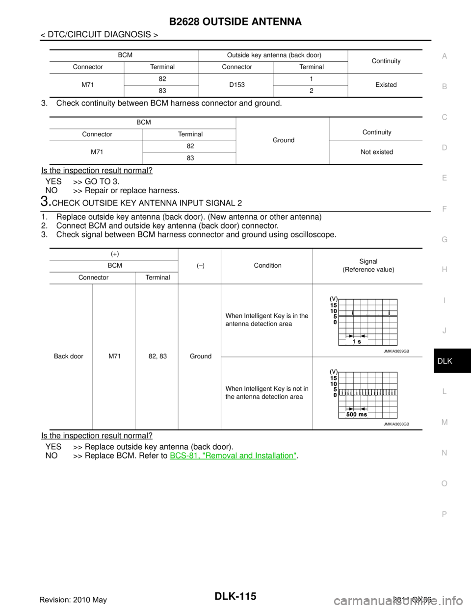
3. Check continuity between BCM harness connector and ground.
Is the inspection result normal?
YES >> GO TO 3.
NO >> Repair or replace harness.
3.CHECK OUTSIDE KEY ANTENNA INPUT SIGNAL 2
1. Replace outside key antenna (back door). (New antenna or other antenna)
2. Connect BCM and outside key antenna (back door) connector.
3. Check signal between BCM harness connector and ground using oscilloscope.
Is the inspection result normal?
YES >> Replace outside key antenna (back door).
NO >> Replace BCM. Refer to BCS-81, "
Removal and Installation".
BCM Outside key antenna (back door)
Continuity
Connector Terminal Connector Terminal
M71 82
D153 1
Existed
83 2
BCM GroundContinuity
Connector Terminal
M71 82
Not existed
83
(+)
(–) Condition Signal
(Reference value)
BCM
Connector Terminal
Back door M71 82, 83 Ground When Intelligent Key is in the
antenna detection area
When Intelligent Key is not in
the antenna detection area
JMKIA3839GB
JMKIA3838GB
Revision: 2010 May2011 QX56
Page 1652 of 5598

DLK-116
< DTC/CIRCUIT DIAGNOSIS >
POWER SUPPLY AND GROUND CIRCUIT
POWER SUPPLY AND GROUND CIRCUIT
AUTOMATIC BACK DOOR CONTROL UNIT
AUTOMATIC BACK DOOR CONTROL UNIT : Diagnosis ProcedureINFOID:0000000006225920
1.CHECK FUSE, FUSIBLE LINK AND CIRCUIT BREAKER
Check that the following fuse, fusible link and circuit breaker are not fusing.
Is the fuse fusing?
YES >> Replace the blown fuse or fusible link after repairing the affected circuit if a fuse or fusible link is blown.
NO >> GO TO 2.
2.CHECK POWER SUPPLY CIRCUIT
1. Turn ignition switch OFF.
2. Disconnect automatic back door control module connector.
3. Check voltage between automatic back door control module harness connector and ground.
Is the measurement value normal?
YES >> GO TO 3.
NO >> Repair or replace harness.
3.CHECK GROUND CIRCUIT
Check continuity between automatic back door control module harness connector and ground.
Does continuity exist?
YES >> INSPECTION END
NO >> Repair or replace harness.
Fuse and fusible link No. Signal name
T (30A) Battery power supply
9 (10A)
4 (10A) Ignition power supply
(+)
(− ) Condition Vol tag e
(Approx.)
Automatic back door control module
Connector Terminal
B26 9
Ground Ignition switch ON
Battery voltage
10
—
28
Automatic back door control module
GroundContinuity
Connector Terminal
B26 34 Existed
Revision: 2010 May2011 QX56
Page 1655 of 5598
DOOR SWITCHDLK-119
< DTC/CIRCUIT DIAGNOSIS >
C
DE
F
G H
I
J
L
M A
B
DLK
N
O P
Is the inspection result normal?
YES >> Replace BCM. Refer to BCS-81, "Removal and Installation".
NO >> Repair or replace harness.
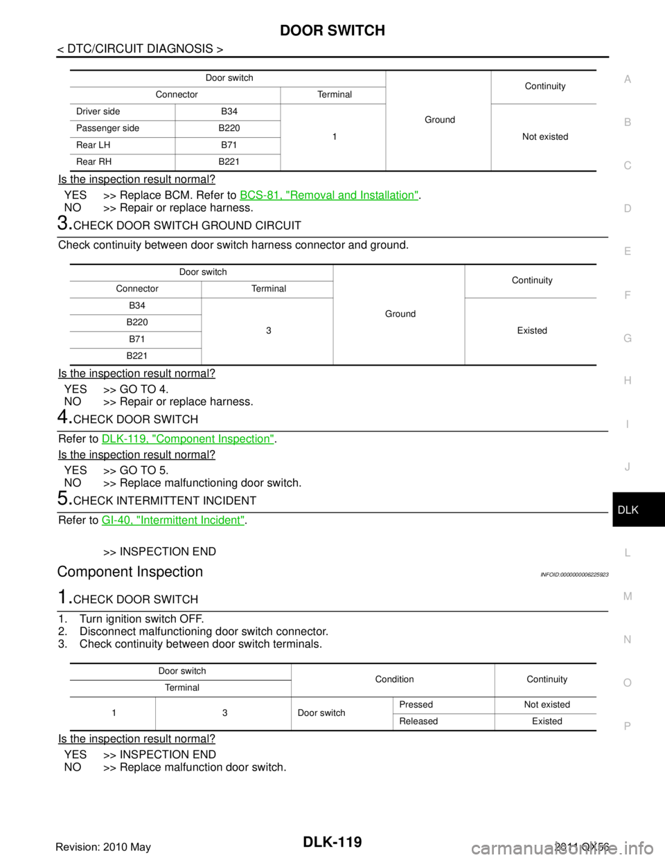
3.CHECK DOOR SWITCH GROUND CIRCUIT
Check continuity between door switch harness connector and ground.
Is the inspection result normal?
YES >> GO TO 4.
NO >> Repair or replace harness.
4.CHECK DOOR SWITCH
Refer to DLK-119, "
Component Inspection".
Is the inspection result normal?
YES >> GO TO 5.
NO >> Replace malfunctioning door switch.
5.CHECK INTERMITTENT INCIDENT
Refer to GI-40, "
Intermittent Incident".
>> INSPECTION END
Component InspectionINFOID:0000000006225923
1.CHECK DOOR SWITCH
1. Turn ignition switch OFF.
2. Disconnect malfunctioning door switch connector.
3. Check continuity between door switch terminals.
Is the inspection result normal?
YES >> INSPECTION END
NO >> Replace malfunction door switch.
Door switch
GroundContinuity
Connector Terminal
Driver side B34
1 Not existed
Passenger side B220
Rear LH B71
Rear RH B221
Door switch
GroundContinuity
Connector Terminal
B34
3Existed
B220
B71
B221
Door switch Condition Continuity
Terminal
1 3 Door switch Pressed Not existed
Released Existed
Revision: 2010 May2011 QX56
Page 1656 of 5598
DLK-120
< DTC/CIRCUIT DIAGNOSIS >
BACK DOOR SWITCH
BACK DOOR SWITCH
Component Function CheckINFOID:0000000006225924
1.CHECK FUNCTION
1. Select “DOOR LOCK” of “BCM” using CONSULT-III.
2. Select “DOOR SW-BK” in “DATA MONITOR” mode.
3. Check that the function operates normall y according to the following conditions.
Is the inspection result normal?
YES >> Door switch is OK.
NO >> Refer to DLK-120, "
Diagnosis Procedure".
Diagnosis ProcedureINFOID:0000000006225925
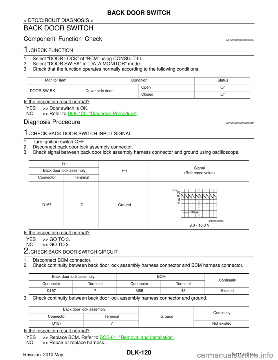
1.CHECK BACK DOOR SWITCH INPUT SIGNAL
1. Turn ignition switch OFF.
2. Disconnect back door lock assembly connector.
3. Check signal between back door lock assembly harness connector and ground using oscilloscope.
Is the inspection result normal?
YES >> GO TO 3.
NO >> GO TO 2.
2.CHECK BACK DOOR SWITCH CIRCUIT
1. Disconnect BCM connector.
2. Check continuity between back door lock as sembly harness connector and BCM harness connector.
3. Check continuity between back door lock assembly harness connector and ground.
Is the inspection result normal?
YES >> Replace BCM. Refer to BCS-81, "Removal and Installation".
NO >> Repair or replace harness.
Monitor item Condition Status
DOOR SW-BK Driver side door Open On
Closed Off
(+)
(–) Signal
(Reference value)
Back door lock assembly
Connector Terminal
D157 7 Ground 9.0 - 10.0 V
JPMIA0593GB
Back door lock assembly BCM Continuity
Connector Terminal Connector Terminal
D157 7 M69 43 Existed
Back door lock assembly GroundContinuity
Connector Terminal
D157 7 Not existed
Revision: 2010 May2011 QX56
Page 1657 of 5598
BACK DOOR SWITCHDLK-121
< DTC/CIRCUIT DIAGNOSIS >
C
DE
F
G H
I
J
L
M A
B
DLK
N
O P
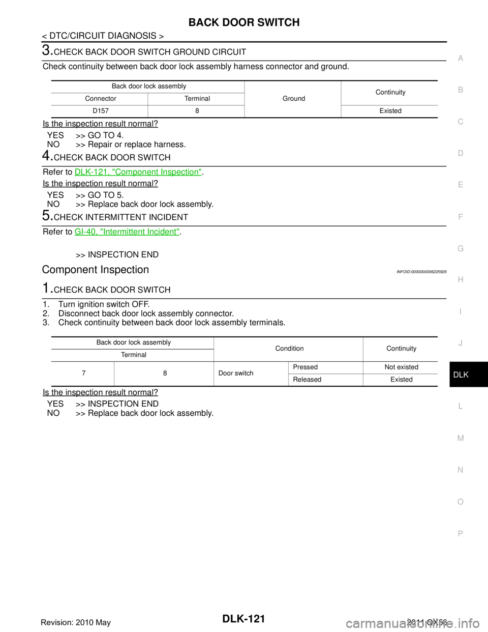
3.CHECK BACK DOOR SWITCH GROUND CIRCUIT
Check continuity between back door lo ck assembly harness connector and ground.
Is the inspection result normal?
YES >> GO TO 4.
NO >> Repair or replace harness.
4.CHECK BACK DOOR SWITCH
Refer to DLK-121, "
Component Inspection".
Is the inspection result normal?
YES >> GO TO 5.
NO >> Replace back door lock assembly.
5.CHECK INTERMITTENT INCIDENT
Refer to GI-40, "
Intermittent Incident".
>> INSPECTION END
Component InspectionINFOID:0000000006225926
1.CHECK BACK DOOR SWITCH
1. Turn ignition switch OFF.
2. Disconnect back door lock assembly connector.
3. Check continuity between back door lock assembly terminals.
Is the inspection result normal?
YES >> INSPECTION END
NO >> Replace back door lock assembly.
Back door lock assembly
GroundContinuity
Connector Terminal
D157 8 Existed
Back door lock assembly Condition Continuity
Terminal
7 8 Door switch Pressed Not existed
Released Existed
Revision: 2010 May2011 QX56
Page 1659 of 5598
DOOR LOCK ACTUATORDLK-123
< DTC/CIRCUIT DIAGNOSIS >
C
DE
F
G H
I
J
L
M A
B
DLK
N
O P
DOOR LOCK ACTUATOR
DRIVER SIDE
DRIVER SIDE : Comp onent Function CheckINFOID:0000000006225931
1.CHECK FUNCTION
1. Select “DOOR LOCK” of “BCM” using CONSULT-III.
2. Select “DOOR LOCK” in “ACTIVE TEST” mode.
3. Touch “ALL LOCK” or “ALL UNLK” to check that it works normally.
Is the inspection result normal?
YES >> Door lock actuator is OK.
NO >> Refer to DLK-123, "
DRIVER SIDE : Diagnosis Procedure".
DRIVER SIDE : Diag nosis ProcedureINFOID:0000000006225932
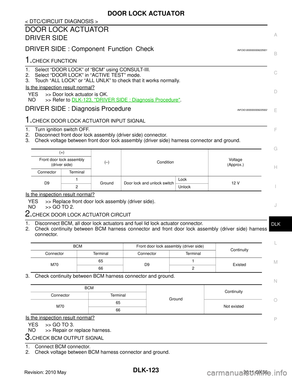
1.CHECK DOOR LOCK ACTUATOR INPUT SIGNAL
1. Turn ignition switch OFF.
2. Disconnect front door lock assembly (driver side) connector.
3. Check voltage between front door lock assembly (driver side) harness connector and ground.
Is the inspection result normal?
YES >> Replace front door lock assembly (driver side).
NO >> GO TO 2.
2.CHECK DOOR LOCK ACTUATOR CIRCUIT
1. Disconnect BCM, all door lock actuator s and fuel lid lock actuator connector.
2. Check continuity between BCM harness connector and front door lock assembly (driver side) harness
connector.
3. Check continuity between BCM harness connector and ground.
Is the inspection result normal?
YES >> GO TO 3.
NO >> Repair or replace harness.
3.CHECK BCM OUTPUT SIGNAL
1. Connect BCM connector.
2. Check voltage between BCM harness connector and ground.
(+)
(–) Condition Vo l ta g e
(Approx.)
Front door lock assembly
(driver side)
Connector Terminal
D9 1
Ground Door lock and unlock switch Lock
12 V
2 Unlock
BCM Front door lock assembly (driver side) Continuity
Connector Terminal Connector Terminal
M70 65
D9 1
Existed
66 2
BCM GroundContinuity
Connector Terminal
M70 65
Not existed
66
Revision: 2010 May2011 QX56
Page 1661 of 5598
DOOR LOCK ACTUATORDLK-125
< DTC/CIRCUIT DIAGNOSIS >
C
DE
F
G H
I
J
L
M A
B
DLK
N
O P
Is the inspection result normal?
YES >> GO TO 3.
NO >> Repair or replace harness.
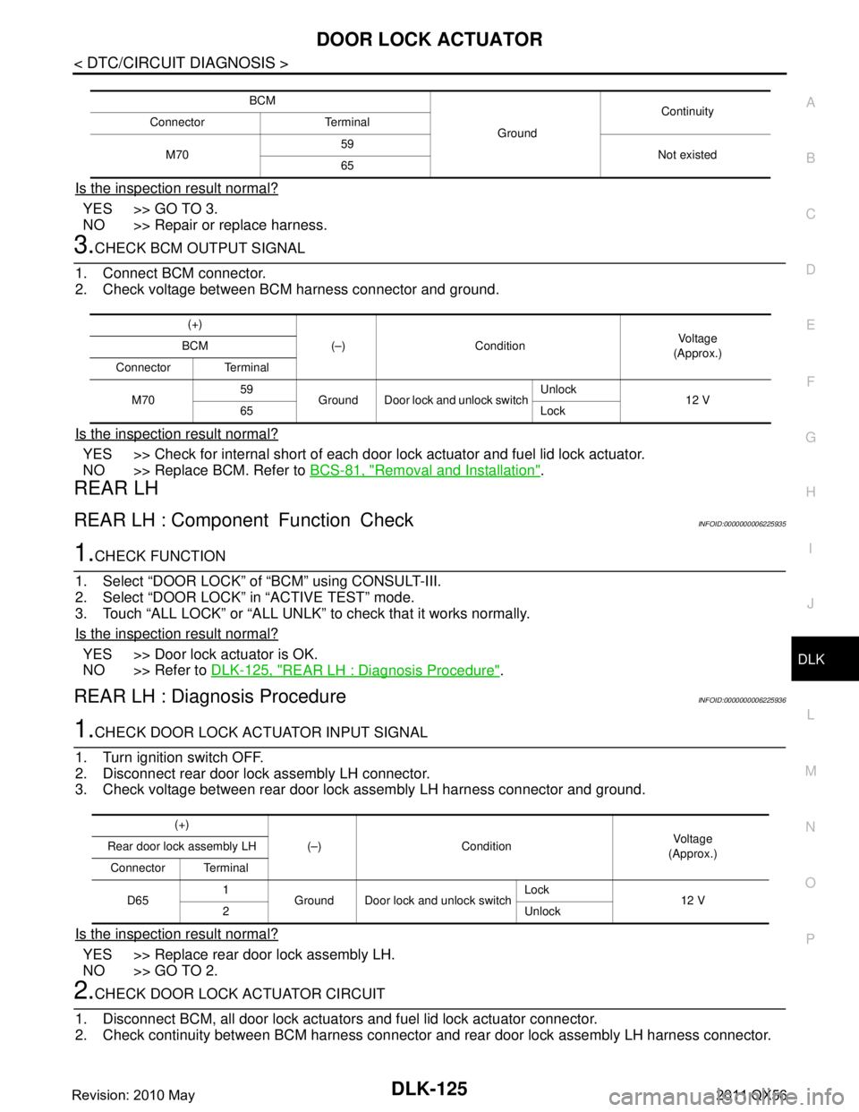
3.CHECK BCM OUTPUT SIGNAL
1. Connect BCM connector.
2. Check voltage between BCM harness connector and ground.
Is the inspection result normal?
YES >> Check for internal short of each door lo ck actuator and fuel lid lock actuator.
NO >> Replace BCM. Refer to BCS-81, "
Removal and Installation".
REAR LH
REAR LH : Component Function CheckINFOID:0000000006225935
1.CHECK FUNCTION
1. Select “DOOR LOCK” of “BCM” using CONSULT-III.
2. Select “DOOR LOCK” in “ACTIVE TEST” mode.
3. Touch “ALL LOCK” or “ALL UNLK” to check that it works normally.
Is the inspection result normal?
YES >> Door lock actuator is OK.
NO >> Refer to DLK-125, "
REAR LH : Diagnosis Procedure".
REAR LH : Diagnosis ProcedureINFOID:0000000006225936
1.CHECK DOOR LOCK ACTUATOR INPUT SIGNAL
1. Turn ignition switch OFF.
2. Disconnect rear door lock assembly LH connector.
3. Check voltage between rear door lock assembly LH harness connector and ground.
Is the inspection result normal?
YES >> Replace rear door lock assembly LH.
NO >> GO TO 2.
2.CHECK DOOR LOCK ACTUATOR CIRCUIT
1. Disconnect BCM, all door lock actuator s and fuel lid lock actuator connector.
2. Check continuity between BCM harness connector and rear door lock assembly LH harness connector.
BCM
GroundContinuity
Connector Terminal
M70 59
Not existed
65
(+)
(–) Condition Vo l ta g e
(Approx.)
BCM
Connector Terminal
M70 59
Ground Door lock and unlock switch Unlock
12 V
65 Lock
(+)
(–) Condition Vo l ta g e
(Approx.)
Rear door lock assembly LH
Connector Terminal
D65 1
Ground Door lock and unlock switch Lock
12 V
2 Unlock
Revision: 2010 May2011 QX56