2011 INFINITI QX56 air condition
[x] Cancel search: air conditionPage 1518 of 5598
DEF-26
< DTC/CIRCUIT DIAGNOSIS >
REAR WINDOW DEFOGGER RELAY
REAR WINDOW DEFOGGER RELAY
DescriptionINFOID:0000000006299436
The rear window defogger is operated by turning the rear window defogger switch ON.
Component Function CheckINFOID:0000000006299437
1.CHECK FUNCTION
1. Perform IPDM E/R Active Test (“REAR DEFOGGER”) using CONSULT-III.
2. Touch “ON”.
3. Check that the rear window heating wire is getting warmer.
Is the inspection result normal?
YES >> Rear window defogger relay function is OK.
NO >> Refer to DEF-26, "
Diagnosis Procedure"
Diagnosis ProcedureINFOID:0000000006299438
1.CHECK FUSE
1. Turn ignition switch OFF.
2. Check the 15A fuse (No. 41, 42 located in IPDM E/R).
Is the inspection result normal?
YES >> GO TO 2.
NO >> Replace the blown fuse after repairing the affected circuit if a fuse is blown.
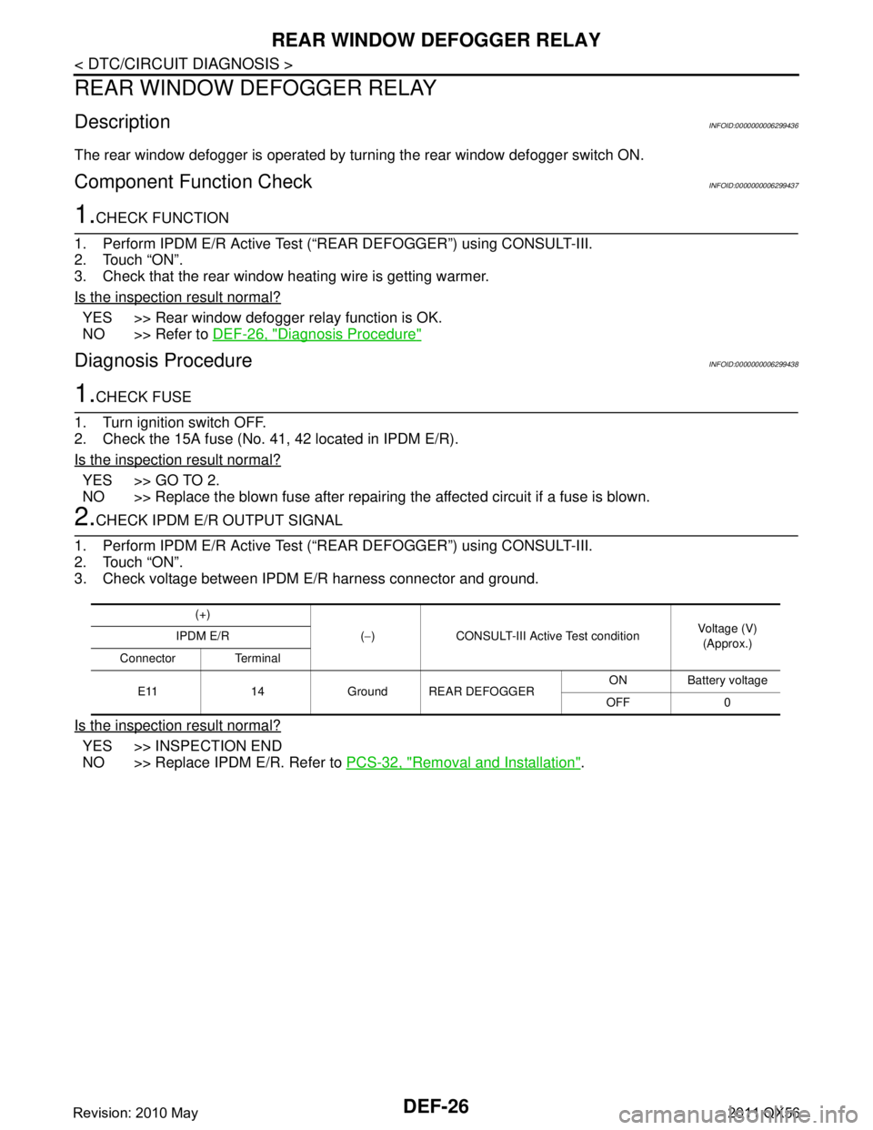
2.CHECK IPDM E/R OUTPUT SIGNAL
1. Perform IPDM E/R Active Test (“REAR DEFOGGER”) using CONSULT-III.
2. Touch “ON”.
3. Check voltage between IPDM E/R harness connector and ground.
Is the inspection result normal?
YES >> INSPECTION END
NO >> Replace IPDM E/R. Refer to PCS-32, "
Removal and Installation".
(+)
(− ) CONSULT-III Active Test condition Voltage (V)
(Approx.)
IPDM E/R
Connector Terminal
E11 14 Ground REAR DEFOGGER ON Battery voltage
OFF 0
Revision: 2010 May2011 QX56
Page 1519 of 5598
REAR WINDOW DEFOGGERDEF-27
< DTC/CIRCUIT DIAGNOSIS >
C
DE
F
G H
I
J
K
M A
B
DEF
N
O P
REAR WINDOW DEFOGGER
DescriptionINFOID:0000000006299439
Heats the heating wire with the power supply from the rear window defogger relay to prevent the rear window
from fogging up.
Component Function CheckINFOID:0000000006299440
1.CHECK FUNCTION
1. Perform IPDM E/R Active Test (“REAR DEFOGGER”) using CONSULT-III.
2. Touch “ON”.
3. Check that the rear window heating wire is getting warmer.
Is the inspection result normal?
YES >> Rear window defogger relay function is OK.
NO >> Refer to DEF-26, "
Diagnosis Procedure"
Diagnosis ProcedureINFOID:0000000006299441
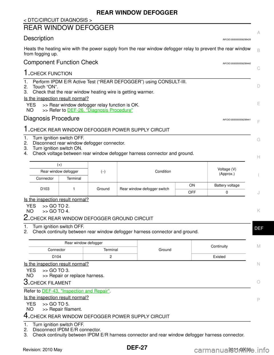
1.CHECK REAR WINDOW DEFOGG ER POWER SUPPLY CIRCUIT
1. Turn ignition switch OFF.
2. Disconnect rear window defogger connector.
3. Turn ignition switch ON.
4. Check voltage between rear window defogger harness connector and ground.
Is the inspection result normal?
YES >> GO TO 2.
NO >> GO TO 4.
2.CHECK REAR WINDOW DE FOGGER GROUND CIRCUIT
1. Turn ignition switch OFF.
2. Check continuity between rear window defogger harness connector and ground.
Is the inspection result normal?
YES >> GO TO 3.
NO >> Repair or replace harness.
3.CHECK FILAMENT
Refer to DEF-43, "
Inspection and Repair".
Is the inspection result normal?
YES >> GO TO 5.
NO >> Repair filament.
4.CHECK REAR WINDOW DEFOGG ER POWER SUPPLY CIRCUIT
1. Turn ignition switch OFF.
2. Disconnect IPDM E/R connector.
3. Check continuity between IPDM E/R harness connector and rear window defogger harness connector.
(+)
(− ) Condition Voltage (V)
(Approx.)
Rear window defogger
Connector Terminal
D103 1 Ground Rear window defogger switch ON Battery voltage
OFF 0
Rear window defogger GroundContinuity
Connector Terminal
D104 2 Existed
Revision: 2010 May2011 QX56
Page 1522 of 5598

DEF-30
< DTC/CIRCUIT DIAGNOSIS >
DRIVER SIDE DOOR MIRROR DEFOGGER
DRIVER SIDE DOOR MIRROR DEFOGGER
DescriptionINFOID:0000000006299445
Heats the heating wire with the power supply from the rear window defogger relay to prevent the door mirror
from fogging up.
Component Function CheckINFOID:0000000006299446
1.CHECK DRIVER SIDE DOOR MIRROR DEFOGGER
1. Perform IPDM E/R Active Test (“REAR DEFOGGER”) using CONSULT-III.
2. Touch “ON”.
3. Check that the driver side door mirror glass is getting warmer.
Is the inspection result normal?
YES >> Driver side door mirror defogger is OK.
NO >> Refer to DEF-30, "
Diagnosis Procedure"
Diagnosis ProcedureINFOID:0000000006299447
1.CHECK POWER SUPPLY CIRCUIT
1. Turn ignition switch OFF.
2. Disconnect door mirror (driver side) connector.
3. Turn ignition switch ON.
4. Check voltage between door mirror (driver side) harness connector and ground.
Is the inspection result normal?
YES >> GO TO 2.
NO >> Repair or replace harness.
2.CHECK GROUND CIRCUIT
1. Turn ignition switch OFF.
2. Check continuity between door mirror (driver side) harness connector and ground.
Is the inspection result normal?
YES >> Replace door mirror glass (driver side).
NO >> Repair or replace harness.
(+)
(–) Condition Voltage (V)
(Approx.)
Door mirror (driver side)
Connector Terminal
D3 7 Ground Rear window defogger
switchON Battery voltage
OFF 0
Door mirror (driver side)
GroundContinuity
Connector Terminal
D3 19 Existed
Revision: 2010 May2011 QX56
Page 1523 of 5598
PASSENGER SIDE DOOR MIRROR DEFOGGERDEF-31
< DTC/CIRCUIT DIAGNOSIS >
C
DE
F
G H
I
J
K
M A
B
DEF
N
O P
PASSENGER SIDE DOOR MIRROR DEFOGGER
DescriptionINFOID:0000000006299448
Heats the heating wire with the power supply from t he rear window defogger relay to prevent the door mirror
from fogging up.
Component Function CheckINFOID:0000000006299449
1.CHECK PASSENGER SIDE DOOR MIRROR DEFOGGER
1. Perform IPDM E/R Active Test (“REAR DEFOGGER”) using CONSULT-III.
2. Touch “ON”.
3. Check that the passenger side door mirror glass is getting warmer.
Is the inspection result normal?
YES >> Passenger side door mirror defogger is OK.
NO >> Refer to DEF-31, "
Diagnosis Procedure"
Diagnosis ProcedureINFOID:0000000006299450
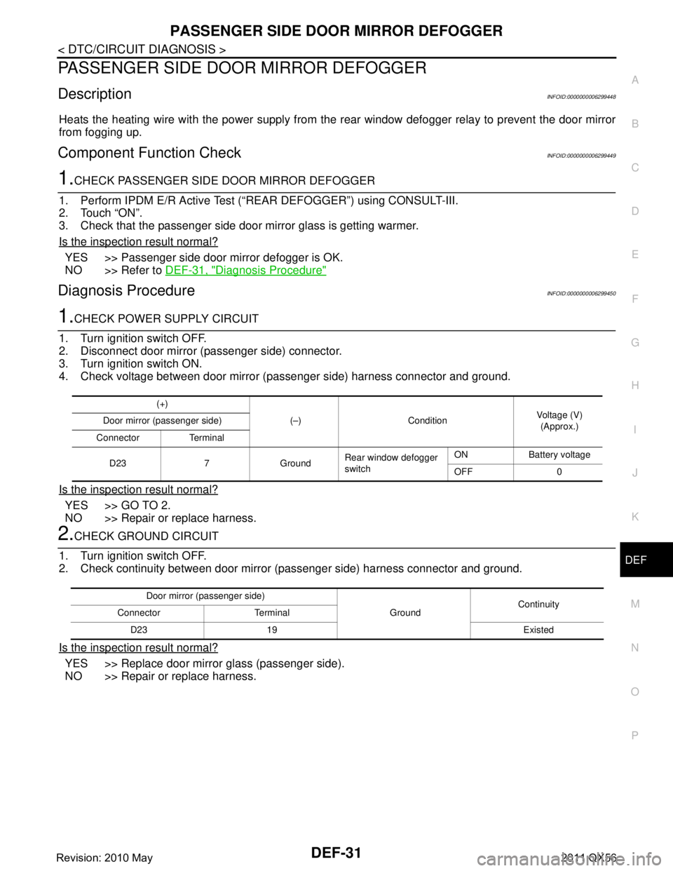
1.CHECK POWER SUPPLY CIRCUIT
1. Turn ignition switch OFF.
2. Disconnect door mirror (passenger side) connector.
3. Turn ignition switch ON.
4. Check voltage between door mirror (passenger side) harness connector and ground.
Is the inspection result normal?
YES >> GO TO 2.
NO >> Repair or replace harness.
2.CHECK GROUND CIRCUIT
1. Turn ignition switch OFF.
2. Check continuity between door mirror (passenger side) harness connector and ground.
Is the inspection result normal?
YES >> Replace door mirror glass (passenger side).
NO >> Repair or replace harness.
(+)
(–) Condition Voltage (V)
(Approx.)
Door mirror (passenger side)
Connector Terminal
D23 7 Ground Rear window defogger
switchON Battery voltage
OFF 0
Door mirror (passenger side)
GroundContinuity
Connector Terminal
D23 19 Existed
Revision: 2010 May2011 QX56
Page 1524 of 5598

DEF-32
< DTC/CIRCUIT DIAGNOSIS >
WIPER DEICER RELAY
WIPER DEICER RELAY
Component Function CheckINFOID:0000000006299451
1.CHECK WIPER DEICER RELAY POWER SUPPLY CIRCUIT
1. Select Active Test (“REAR DEFOGGER”) mode of “BCM” using CONSULT-III.
2. Touch “ON”.
3. Check that the front window heating wire is getting warmer.
Is the inspection result normal?
YES >> Wiper deicer relay power supply circuit function is OK.
NO >> Refer to DEF-32, "
Diagnosis Procedure".
Diagnosis ProcedureINFOID:0000000006299452
1.CHECK WIPER DEICER CIRCUIT 1
1. Turn ignition switch ON.
2. Check voltage between wiper deicer relay harness connector and ground.
Is the inspection result normal?
YES >> GO TO 3.
NO >> GO TO 2.
2.CHECK WIPER DEICER CIRCUIT 2
1. Turn ignition switch OFF.
2. Disconnect wiper deicer relay and IPDM E/R connector.
3. Check continuity between wiper deicer relay terminal connector and IPDM E/R harness connector.
Is the inspection result normal?
YES >> GO TO 6.
NO >> Repair or replace harness.
3.CHECK WIPER DEICER CIRCUIT 3
Check voltage between wiper deicer relay harness connector and ground.
Is the inspection result normal?
YES >> GO TO 4.
NO >> Repair or replace harness.
4.CHECK WIPER DEICER RELAY GROUND CIRCUIT
1. Turn ignition switch OFF.
2. Disconnect wiper deicer relay connector.
3. Check continuity between wiper deicer relay terminal connector and ground.
(+)
(–) Condition Voltage (V)
(Approx.)
Wiper deicer relay
Connector Terminal
E23 1 Ground Rear window defogger switch: ON Battery voltage
Rear window defogger switch: OFF 0
Wiper deicer relay IPDM E/R
Continuity
Connector Terminal Connector Terminal
E23 1 E11 14 Existed
(+) (–)Voltage (V)
(Approx.)
Wiper deicer relay
Connector Terminal E23 3 Ground Battery voltage
Revision: 2010 May2011 QX56
Page 1525 of 5598
WIPER DEICER RELAYDEF-33
< DTC/CIRCUIT DIAGNOSIS >
C
DE
F
G H
I
J
K
M A
B
DEF
N
O P
Is the inspection result normal?
YES >> GO TO 5.
NO >> Repair or replace harness.
5.CHECK WIPER DEICER RELAY
Check wiper deicer relay.
Refer to DEF-33, "
Component Inspection".
Is the inspection result normal?
YES >> GO TO 6.
NO >> Replace wiper deicer relay.
6.CHECK INTERMITTENT INCIDENT
Check intermittent incident.
Refer to GI-40, "
Intermittent Incident".
>> INSPECTION END
Component InspectionINFOID:0000000006299453
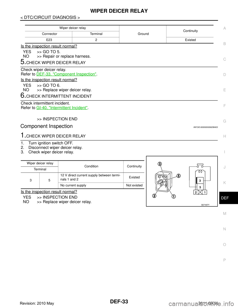
1.CHECK WIPER DEICER RELAY
1. Turn ignition switch OFF.
2. Disconnect wiper deicer relay.
3. Check wiper deicer relay.
Is the inspection result normal?
YES >> INSPECTION END
NO >> Replace wiper deicer relay.
Wiper deicer relay
GroundContinuity
Connector Terminal
E23 2 Existed
Wiper deicer relay Condition Continuity
Te r m i n a l
35 12 V direct current supply between termi-
nals 1 and 2
Existed
No current supply Not existed
SEF497Y
Revision: 2010 May2011 QX56
Page 1526 of 5598

DEF-34
< DTC/CIRCUIT DIAGNOSIS >
WIPER DEICER
WIPER DEICER
Component Function CheckINFOID:0000000006299454
1.CHECK WIPER DEICER
1. Select Active Test (“REAR DEFOGGER”) mode of “BCM” using CONSULT-III.
2. Touch “ON”.
3. Check that the front window heating wire is getting warmer.
Is the inspection result normal?
YES >> Wiper deicer is OK.
NO >> Refer to DEF-34, "
Diagnosis Procedure"
Diagnosis ProcedureINFOID:0000000006299455
1.CHECK FUSE
1. Turn ignition switch OFF.
2. Check 15 A fuse [No.75, located in fuse block (J/B)]
Is the inspection result normal?
YES >> GO TO 2.
NO >> Replace the blown fuse after repairing the affected circuit if a fuse is blown.
2.CHECK POWER SUPPLY CIRCUIT
1. Turn ignition switch ON.
2. Check voltage between wiper deicer harness connector and ground.
Is the inspection result normal?
YES >> GO TO 3.
NO >> GO TO 4.
3.CHECK GROUND CIRCUIT
1. Turn ignition switch OFF.
2. Disconnect wiper deicer connector.
3. Check continuity between wiper deicer harness connector and ground.
Is the inspection result normal?
YES >> GO TO 5.
NO >> Repair or replace harness between rear window defogger and ground.
4.CHECK WIPER DEICER CIRCUIT
1. Turn ignition switch OFF.
2. Disconnect wiper deicer relay connector and wiper deicer connector.
3. Check continuity between wiper deicer relay harness connector and wiper deicer harness connector.
(+)
(–) Condition Voltage (V)
(Approx.)
Wiper deicer
Connector Terminal
E40 1 Ground Rear window defogger switch: ON Battery voltage
Rear window defogger switch: OFF 0
Wiper deicer
GroundContinuity
Connector Terminal
E40 2 Existed
Revision: 2010 May2011 QX56
Page 1545 of 5598
PRECAUTIONSDLK-9
< PRECAUTION >
C
DE
F
G H
I
J
L
M A
B
DLK
N
O P
5. When the repair work is completed, re-connect both battery cables. With the brake pedal released, turn
the push-button ignition switch from ACC position to ON position, then to LOCK position. (The steering
wheel will lock when the push-button ignition switch is turned to LOCK position.)
6. Perform self-diagnosis check of a ll control units using CONSULT-III.
Precautions For Xenon Headlamp ServiceINFOID:0000000006225830
WARNING:
Comply with the follow ing warnings to prevent any serious accident.
Disconnect the battery cable (neg ative terminal) or the power supply fuse before installing, remov-
ing, or touching the xenon headlamp (bulb included). The xenon headlamp contains high-voltage
generated parts.
Never work with wet hands.
Check the xenon headlamp ON-OFF status after assem bling it to the vehicle. Never turn the xenon
headlamp ON in other conditions. Connect th e power supply to the vehicle-side connector.
(Turning it ON outside the lamp case m ay cause fire or visual impairments.)
Never touch the bulb glass immediately afte r turning it OFF. It is extremely hot.
CAUTION:
Comply with the follow ing cautions to prevent an y error and malfunction.
Install the xenon bulb securely. (I nsufficient bulb socket installation may melt the bulb, the connec-
tor, the housing, etc. by high-vol tage leakage or corona discharge.)
Never perform HID circuit inspection with a tester.
Never touch the xenon bulb glass with ha nds. Never put oil and grease on it.
Dispose of the used xenon bulb after p acking it in thick vinyl without breaking it.
Never wipe out dirt and cont amination with organic solven t (thinner, gasoline, etc.).
WorkINFOID:0000000006225831
After removing and installing the opening/closing parts, be sure to carry out fitting adjustments to check their
operational.
Check the lubrication level, damage, and wear of each part. If necessary, grease or replace it.
Revision: 2010 May2011 QX56