2011 INFINITI QX56 relay
[x] Cancel search: relayPage 5525 of 5598
WW-6
< SYSTEM DESCRIPTION >
COMPONENT PARTS
Component Description
INFOID:0000000006300449
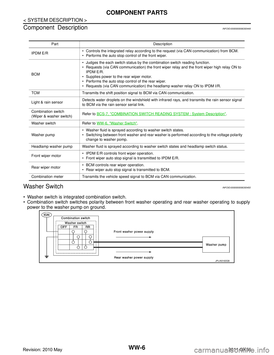
Washer SwitchINFOID:0000000006300450
Washer switch is integrated combination switch.
Combination switch switches polarity between front washer operating and rear washer operating to supply
power to the washer pump on ground.
Part Description
IPDM E/R Controls the integrated relay according to the request (via CAN communication) from BCM.
Performs the auto stop control of the front wiper.
BCM Judges the each switch status by the combination switch reading function.
Requests (via CAN communication) the front wiper relay and the front wiper high relay ON to
IPDM E/R.
Supplies power to the rear wiper motor.
Performs the auto stop control of the rear wiper.
Requests (via CAN communication) the headlamp washer relay ON to IPDM I/R.
TCM Transmits the shift position signal to BCM via CAN communication.
Light & rain sensor Detects water droplets on the windshield with infrared rays, and transmits the rain sensor signal
to BCM via the rain sensor serial link.
Combination switch
(Wiper & washer switch) Refer to
BCS-7, "
COMBINATION SWITCH READING S YSTEM : System Description".
Washer switch Refer to WW-6, "
Washer Switch".
Washer pump Washer fluid is sprayed according to washer switch states.
Switching between front washer and rear washer is performed according to the voltage polarity
change to washer pomp.
Headlamp washer pump Washer fluid is sprayed according to washer switch states and headlamp switch status.
Front wiper motor IPDM E/R controls front wiper operation.
Front wiper auto stop signal is transmitted to IPDM E/R.
Rear wiper motor BCM controls rear wiper operation.
Rear wiper auto stop signal is transmitted to BCM.
Combination meter Transmits the vehicle speed signal to BCM via CAN communication.
JPLIA0163GB
Revision: 2010 May2011 QX56
Page 5526 of 5598
SYSTEMWW-7
< SYSTEM DESCRIPTION >
C
DE
F
G H
I
J
K
M A
B
WW
N
O P
SYSTEM
FRONT WIPER AND WASHER SYSTEM
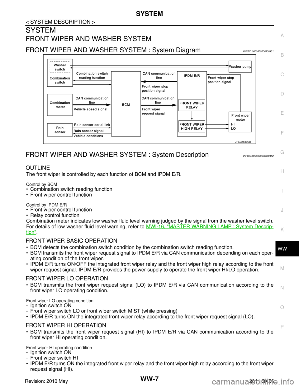
FRONT WIPER AND WASHER SYSTEM : System DiagramINFOID:0000000006300451
FRONT WIPER AND WASHER S YSTEM : System DescriptionINFOID:0000000006300452
OUTLINE
The front wiper is controlled by each function of BCM and IPDM E/R.
Control by BCM
Combination switch reading function
Front wiper control function
Control by IPDM E/R
Front wiper control function
Relay control function
Combination meter indicates low washer fluid level warning judged by the signal from the washer level switch.
For details of low washer fluid level warning, refer to MWI-16, "
MASTER WARNING LAMP : System Descrip-
tion".
FRONT WIPER BASIC OPERATION
BCM detects the combination switch condition by the combination switch reading function.
BCM transmits the front wiper request signal to IPDM E/R via CAN communication depending on each oper-
ating condition of the front wiper.
IPDM E/R turns ON/OFF the integrated front wiper rela y and the front wiper high relay according to the front
wiper request signal. IPDM E/R provides the power supply to operate the front wiper HI/LO operation.
FRONT WIPER LO OPERATION
BCM transmits the front wiper request signal (LO) to IPDM E/R via CAN communication according to the
front wiper LO operating condition.
Front wiper LO operating condition
- Ignition switch ON
- Front wiper switch LO or front wiper switch MIST (while pressing)
IPDM E/R turns ON the integrated front wiper rela y according to the front wiper request signal (LO).
FRONT WIPER HI OPERATION
BCM transmits the front wiper request signal (HI) to IPDM E/R via CAN communication according to the
front wiper HI operating condition.
Front wiper HI operating condition
- Ignition switch ON
- Front wiper switch HI
IPDM E/R turns ON the integrated front wiper relay and the front wiper high relay according to the front wiper
request signal (HI).
JPLIA1630GB
Revision: 2010 May2011 QX56
Page 5528 of 5598
SYSTEMWW-9
< SYSTEM DESCRIPTION >
C
DE
F
G H
I
J
K
M A
B
WW
N
O P
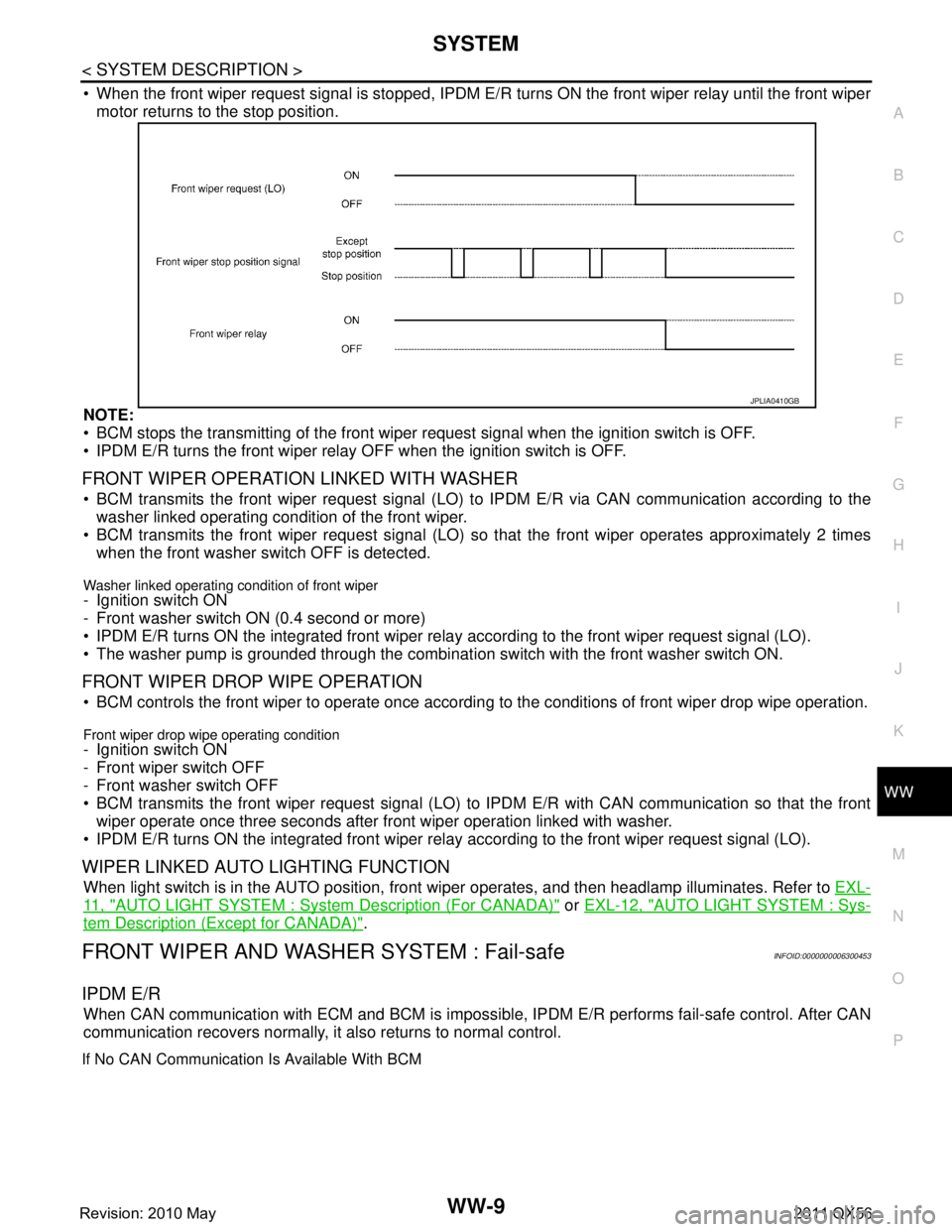
When the front wiper request signal is stopped, IPDM E/R turns ON the front wiper relay until the front wiper
motor returns to the stop position.
NOTE:
BCM stops the transmitting of the front wiper request signal when the ignition switch is OFF.
IPDM E/R turns the front wiper relay OFF when the ignition switch is OFF.
FRONT WIPER OPERATION LINKED WITH WASHER
BCM transmits the front wiper request signal (LO) to IPDM E/R via CAN communication according to the
washer linked operating condition of the front wiper.
BCM transmits the front wiper request signal (LO) so that the front wiper operates approximately 2 times
when the front washer switch OFF is detected.
Washer linked operating condition of front wiper
- Ignition switch ON
- Front washer switch ON (0.4 second or more)
IPDM E/R turns ON the integrated front wiper rela y according to the front wiper request signal (LO).
The washer pump is grounded through the combinati on switch with the front washer switch ON.
FRONT WIPER DROP WIPE OPERATION
BCM controls the front wiper to operate once according to the conditions of front wiper drop wipe operation.
Front wiper drop wipe operating condition
- Ignition switch ON
- Front wiper switch OFF
- Front washer switch OFF
BCM transmits the front wiper request signal (LO) to IPDM E/R with CAN communication so that the front
wiper operate once three seconds after fr ont wiper operation linked with washer.
IPDM E/R turns ON the integrated front wiper rela y according to the front wiper request signal (LO).
WIPER LINKED AUTO LIGHTING FUNCTION
When light switch is in the AUTO position, front wiper operates, and then headlamp illuminates. Refer to EXL-
11 , "AUTO LIGHT SYSTEM : System Description (For CANADA)" or EXL-12, "AUTO LIGHT SYSTEM : Sys-
tem Description (Except for CANADA)".
FRONT WIPER AND WASHER SYSTEM : Fail-safeINFOID:0000000006300453
IPDM E/R
When CAN communication with ECM and BCM is impossible, IPDM E/R performs fail-safe control. After CAN
communication recovers normally, it also returns to normal control.
If No CAN Communication Is Available With BCM
JPLIA0410GB
Revision: 2010 May2011 QX56
Page 5529 of 5598
WW-10
< SYSTEM DESCRIPTION >
SYSTEM
IPDM E/R detects front wiper stop position by a front wiper stop position signal.
When a front wiper stop position signal is in the conditi ons listed below, IPDM E/R stops power supply to wiper
after repeating a front wiper 10 seconds activation and 20 seconds stop five times.
NOTE:
This operation status can be confirmed on the IPDM E/ R “Data Monitor” that displays “BLOCK” for the item
“WIP PROT” while the wiper is stopped.
BCM
BCM detects the rain sensor serial link error and the light & rain sensor malfunction.
BCM controls the following fail-safe when light & rain sensor has a malfunction.
Fail-safe Control
Front wiper control
- Front wiper switch AUTO and sensing rain drop: The c ondition just before the activation of fail-safe is main-
tained until the front wiper switch is turned OFF.
- Front wiper switch AUTO and not sensing rain drop: Front wiper is LO operation until the front wiper switch is
turned off.
REAR WIPER AND WASHER SYSTEM
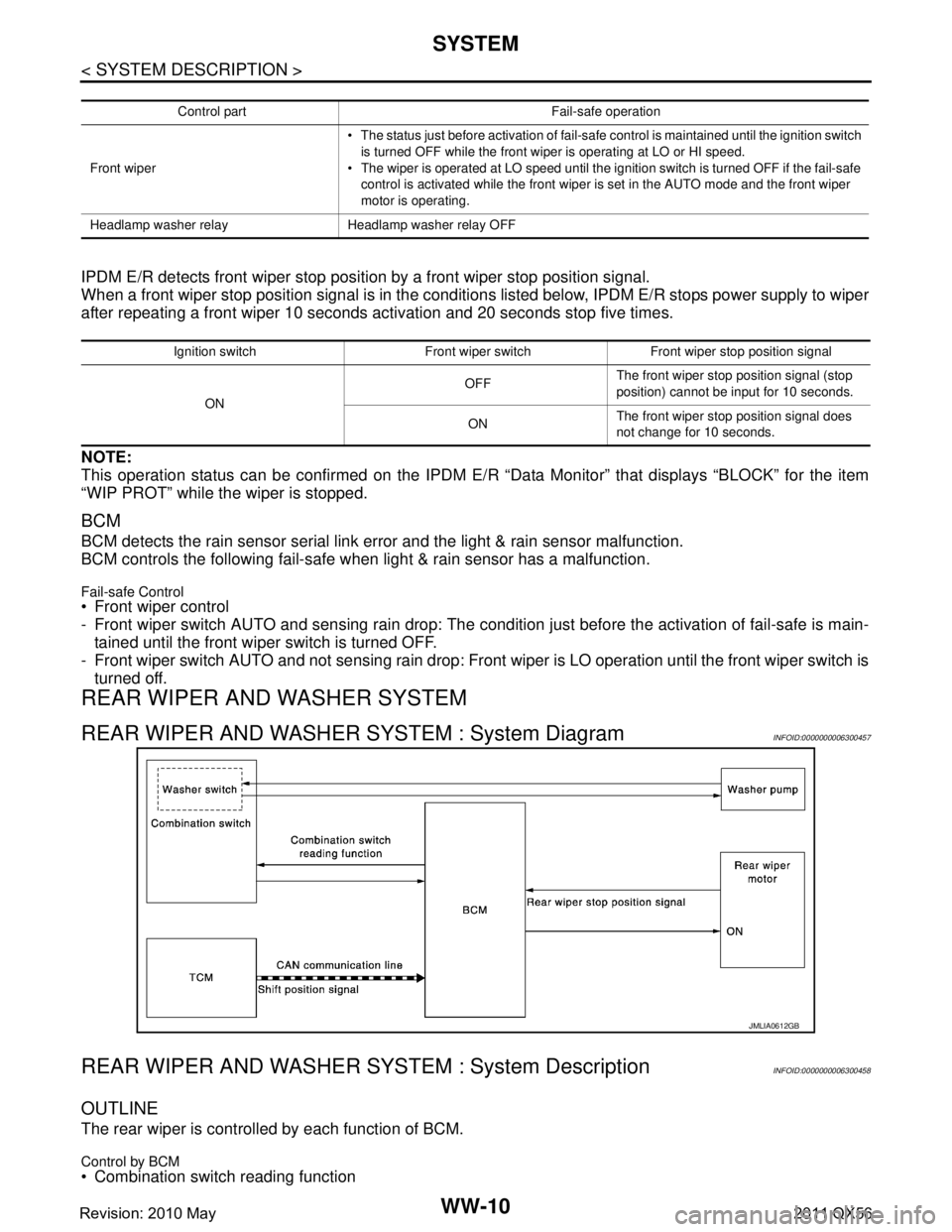
REAR WIPER AND WASHER SYSTEM : System DiagramINFOID:0000000006300457
REAR WIPER AND WASHER S YSTEM : System DescriptionINFOID:0000000006300458
OUTLINE
The rear wiper is controlled by each function of BCM.
Control by BCM
Combination switch reading function
Control part Fail-safe operation
Front wiper The status just before activation of fail-safe control is maintained until the ignition switch
is turned OFF while the front wiper is operating at LO or HI speed.
The wiper is operated at LO speed until the ignition switch is turned OFF if the fail-safe
control is activated while the front wiper is set in the AUTO mode and the front wiper
motor is operating.
Headlamp washer relay Headlamp washer relay OFF
Ignition switch Front wiper switch Front wiper stop position signal
ON OFF
The front wiper stop position signal (stop
position) cannot be input for 10 seconds.
ON The front wiper stop position signal does
not change for 10 seconds.
JMLIA0612GB
Revision: 2010 May2011 QX56
Page 5532 of 5598
SYSTEMWW-13
< SYSTEM DESCRIPTION >
C
DE
F
G H
I
J
K
M A
B
WW
N
O P
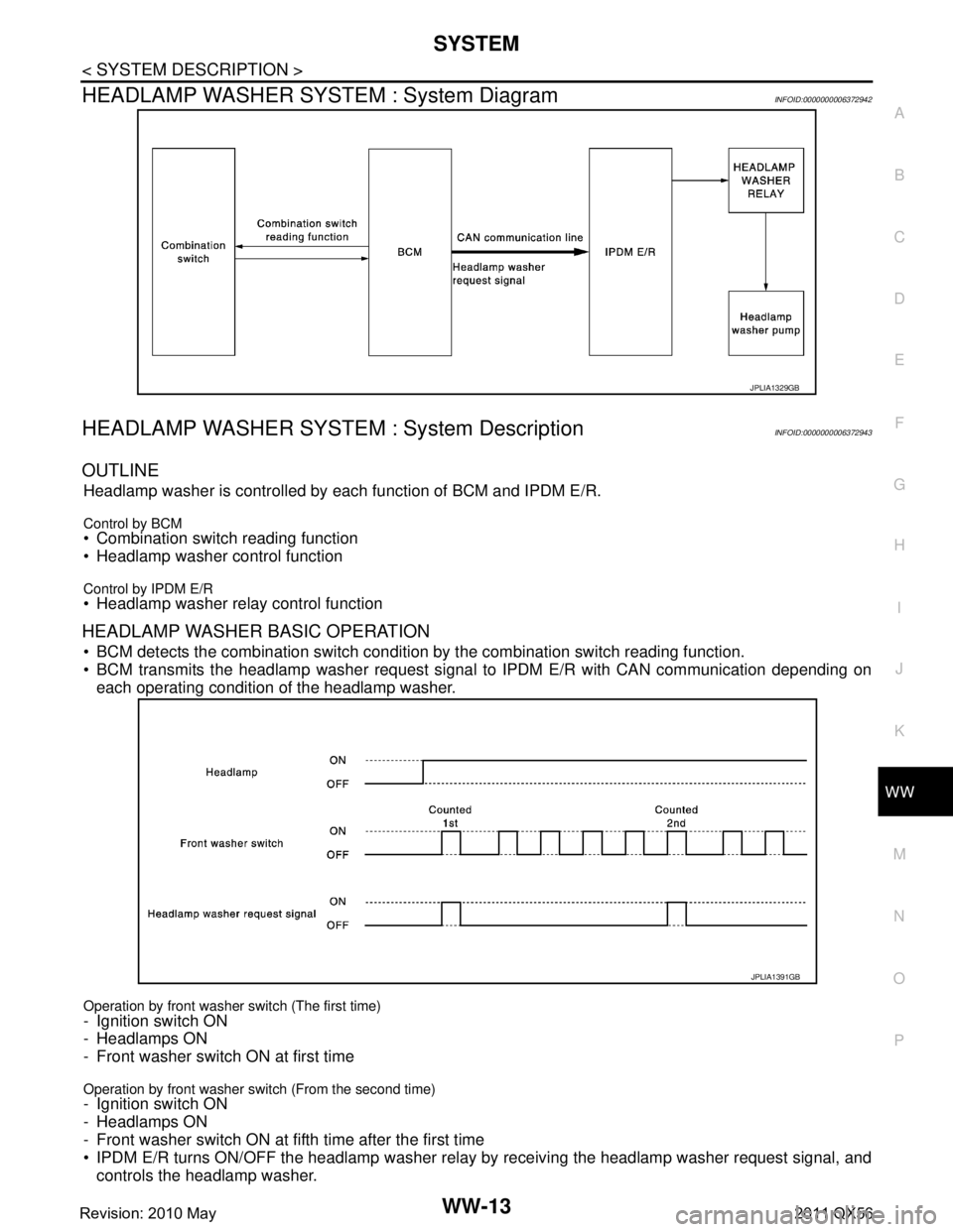
HEADLAMP WASHER SYSTEM : System DiagramINFOID:0000000006372942
HEADLAMP WASHER SYSTEM : System DescriptionINFOID:0000000006372943
OUTLINE
Headlamp washer is controlled by each function of BCM and IPDM E/R.
Control by BCM Combination switch reading function
Headlamp washer control function
Control by IPDM E/R Headlamp washer relay control function
HEADLAMP WASHER BASIC OPERATION
BCM detects the combination switch conditi on by the combination switch reading function.
BCM transmits the headlamp washer request signal to IPDM E/R with CAN communication depending on
each operating condition of the headlamp washer.
Operation by front washer switch (The first time)
- Ignition switch ON
- Headlamps ON
- Front washer switch ON at first time
Operation by front washer switch (From the second time)- Ignition switch ON
- Headlamps ON
- Front washer switch ON at fifth time after the first time
IPDM E/R turns ON/OFF the headlamp washer relay by receiving the headlamp washer request signal, and
controls the headlamp washer.
JPLIA1329GB
JPLIA1391GB
Revision: 2010 May2011 QX56
Page 5539 of 5598

WW-20
< SYSTEM DESCRIPTION >
DIAGNOSIS SYSTEM (IPDM E/R)
CONSULT-III Function (IPDM E/R)
INFOID:0000000006349815
APPLICATION ITEM
CONSULT-III performs the following functions via CAN communication with IPDM E/R.
SELF DIAGNOSTIC RESULT
Refer to PCS-22, "DTCIndex".
DATA MONITOR
Monitor item
Oil pressure warning lamp does not operate Perform auto active test.
Does the oil pressure warning
lamp blink?YES
Harness or connector be-
tween IPDM E/R and oil
pressure switch
Oil pressure switch
IPDM E/R
NO CAN communication signal
between IPDM E/R and
BCM
CAN communication signal
between BCM and combi-
nation meter
Combination meter
Symptom Inspection contents Possible cause
Diagnosis mode Description
Ecu Identification Allows confirmation of IPDM E/R part number.
Self Diagnostic Result Displays the diagnosis results judged by IPDM E/R.
Data Monitor Displays the real-time input/output data from IPDM E/R input/output data.
Active Test IPDM E/R can provide a drive signal to electronic components to check their operations.
CAN Diag Support Monitor The results of transmit/receive diagnosis of CAN communication can be read.
Monitor Item [Unit] MAIN SIG-
NALS Description
RAD FAN REQ
[1/2/3/4] ×Displays the value of the cooling fan speed request signal received from ECM via
CAN communication.
AC COMP REQ
[Off/On] ×Displays the status of the A/C compressor request signal received from ECM via
CAN communication.
TA I L & C L R R E Q
[Off/On] ×
Displays the status of the position light request signal received from BCM via CAN
communication.
HL LO REQ
[Off/On] ×Displays the status of the low beam request signal received from BCM via CAN
communication.
HL HI REQ
[Off/On] ×Displays the status of the high beam request signal received from BCM via CAN
communication.
FR FOG REQ
[Off/On] ×Displays the status of the front fog light request signal received from BCM via
CAN communication.
FR WIP REQ
[Stop/1LOW/Low/Hi] ×
Displays the status of the front wiper request signal received from BCM via CAN
communication.
WIP AUTO STOP
[STOP P/ACT P] ×
Displays the status of the front wiper auto stop signal judged by IPDM E/R.
WIP PROT
[Off/BLOCK] ×
Displays the status of the front wiper fail-safe operation judged by IPDM E/R.
IGN RLY1 -REQ
[Off/On] Displays the status of the ignition switch ON signal received from BCM via CAN
communication.
IGN RLY
[Off/On] ×
Displays the status of the ignition relay judged by IPDM E/R.
Revision: 2010 May2011 QX56
Page 5540 of 5598
![INFINITI QX56 2011 Factory Service Manual
DIAGNOSIS SYSTEM (IPDM E/R)WW-21
< SYSTEM DESCRIPTION >
C
DE
F
G H
I
J
K
M A
B
WW
N
O P
ACTIVE TEST
Te s t i t e m
PUSH SW
[Off/On] Displays the status of the push-button ignition switch judged by I INFINITI QX56 2011 Factory Service Manual
DIAGNOSIS SYSTEM (IPDM E/R)WW-21
< SYSTEM DESCRIPTION >
C
DE
F
G H
I
J
K
M A
B
WW
N
O P
ACTIVE TEST
Te s t i t e m
PUSH SW
[Off/On] Displays the status of the push-button ignition switch judged by I](/manual-img/42/57033/w960_57033-5539.png)
DIAGNOSIS SYSTEM (IPDM E/R)WW-21
< SYSTEM DESCRIPTION >
C
DE
F
G H
I
J
K
M A
B
WW
N
O P
ACTIVE TEST
Te s t i t e m
PUSH SW
[Off/On] Displays the status of the push-button ignition switch judged by IPDM E/R.
INTER/NP SW
[Off/On] Displays the status of the shift position judged by IPDM E/R.
ST RLY CONT
[Off/On] Displays the status of the starter relay status signal received from BCM via CAN
communication.
IHBT RLY -REQ
[Off/On] Displays the status of the starter control relay signal received from BCM via CAN
communication.
ST/INHI RLY
[Off/ ST ON/INHI ON/UNKWN] Displays the status of the starter relay and starter control relay judged by IPDM
E/R.
DETENT SW
[Off/On] Displays the status of the A/T shift selector (detention switch) judged by IPDM E/
R.
S/L RLY -REQ
[Off/On] Displays the status of the steering lock relay signal received from BCM via CAN
communication.
S/L STATE
[LOCK/UNLK/UNKWN] Displays the status of the steering lock judged by IPDM E/R.
OIL P SW
[Open/Close] Displays the status of the oil pressure switch judged by IPDM E/R.
HOOD SW
[Off/On] Displays the status of the hood switch judged by IPDM E/R.
HL WASHER REQ
[Off/On] Displays the status of the headlamp washer request signal received from BCM via
CAN communication.
THFT HRN REQ
[Off/On] Displays the status of the theft warning horn request signal received from BCM
via CAN communication.
HORN CHIRP
[Off/On] Displays the status of the horn reminder signal received from BCM via CAN com-
munication.
Monitor Item
[Unit] MAIN SIG-
NALS Description
Test item Operation Description
CORNERING LAMP LH
NOTE:
This item is indicated, but cannot be tested.
RH
HORN On Operates horn relay for 20 ms.
REAR DEFOGGER Off OFF
On Operates the rear window defogger relay.
FRONT WIPER Off OFF
Lo Operates the front wiper relay.
Hi Operates the front wiper relay and front wiper high relay.
MOTOR FAN* 1OFF
2 Transmits 50% pulse duty signal (PWM signal) to the cooling fan control module.
3 Transmits 75% pulse duty signal (PWM signal) to the cooling fan control module.
4
Transmits 100% pulse duty signal (PWM signal) to the cooling fan control mod-
ule.
HEAD LAMP WASHER On Operates the headlamp washer relay for 1 second.
Revision: 2010 May2011 QX56
Page 5541 of 5598

WW-22
< SYSTEM DESCRIPTION >
DIAGNOSIS SYSTEM (IPDM E/R)
*: Operates while the engine is running.EXTERNAL LAMPS
Off OFF
TAIL Operates the tail lamp relay.
Lo Operates the headlamp low relay.
Hi
Operates the headlamp low relay and ON/OFF the headlamp high relay at 1 sec-
ond intervals.
Fog Operates the front fog lamp relay.
Test item Operation Description
Revision: 2010 May2011 QX56