2011 INFINITI QX56 relay
[x] Cancel search: relayPage 5013 of 5598

ST-26
< SYMPTOM DIAGNOSIS >
HEATED STEERING WHEEL SWITCH INDICATOR LAMP DOES NOT TURN ON
HEATED STEERING WHEEL SWITCH INDICATOR LAMP DOES NOT
TURN ON
Description INFOID:0000000006225594
Heated steering wheel switch indicator lamp does not turn on the lamp.
Heated steering wheel switch indicator lamp does not turn off the lamp.
Diagnosis ProcedureINFOID:0000000006225595
1.CHECK POWER SOURCE AND GROUND CIRCUIT
1. Turn ignition switch ON. CAUTION:
Never start the engine.
2. Turn heated steering wheel switch ON.
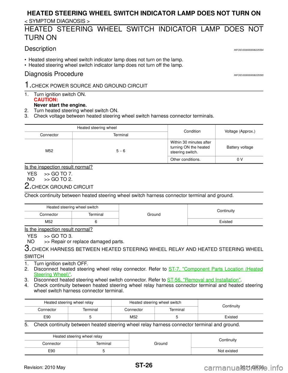
3. Check voltage between heated steering wheel switch harness connector terminals.
Is the inspection result normal?
YES >> GO TO 7.
NO >> GO TO 2.
2.CHECK GROUND CIRCUIT
Check continuity between heated steering wheel switch harness connector terminal and ground.
Is the inspection result normal?
YES >> GO TO 3.
NO >> Repair or replace damaged parts.
3.CHECK HARNESS BETWEEN HEATED STEERING WHEEL RELAY AND HEATED STEERING WHEEL
SWITCH
1. Turn ignition switch OFF.
2. Disconnect heated steering wheel relay connector. Refer to ST-7, "
Component Parts Location (Heated
Steering Wheel)".
3. Disconnect heated steering wheel switch connector. Refer to ST-56, "
Removal and Installation".
4. Check continuity between heated steering wheel relay harness connector terminal and heated steering
wheel switch harness connector terminal.
5. Check continuity between heated steering w heel relay harness connector terminal and ground.
Heated steering wheel
Condition Voltage (Approx.)
Connector Terminal
M52 5 − 6 Within 30 minutes after
turning ON the heated
steering switch.
Battery voltage
Other conditions. 0 V
Heated steering wheel switch GroundContinuity
Connector Terminal
M52 6 Existed
Heated steering wheel relay Heated steering wheel switch Continuity
Connector Terminal Connector Terminal
E90 5 M52 5 Existed
Heated steering wheel relay GroundContinuity
Connector Terminal
E90 5 Not existed
Revision: 2010 May2011 QX56
Page 5014 of 5598

HEATED STEERING WHEEL SWITCH INDICATOR LAMP DOES NOT TURN ON
ST-27
< SYMPTOM DIAGNOSIS >
C
D E
F
H I
J
K L
M A
B
ST
N
O P
Is the inspection result normal?
YES >> GO TO 4.
NO >> Repair or replace damaged parts.
4.CHECK HEATED STEERING WHEEL RELAY
Check heated steering wheel relay. Refer to ST-22, "
Component Inspection (Heated Steering Wheel Relay)".
Is the inspection result normal?
YES >> GO TO 5.
NO >> Replace heated steering wheel relay. Refer to ST-7, "
Component Parts Location (Heated Steering
Wheel)".
5.CHECK HARNESS BETWEEN HEATED STEERING WHEEL RELAY AND HEATED STEERING WHEEL
SWITCH
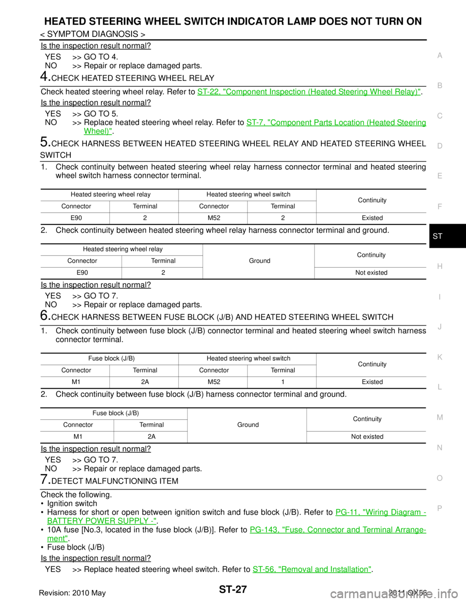
1. Check continuity between heated steering wheel relay harness connector terminal and heated steering
wheel switch harness connector terminal.
2. Check continuity between heated steering w heel relay harness connector terminal and ground.
Is the inspection result normal?
YES >> GO TO 7.
NO >> Repair or replace damaged parts.
6.CHECK HARNESS BETWEEN FUSE BLOCK (J/B) AND HEATED STEERING WHEEL SWITCH
1. Check continuity between fuse block (J/B) connec tor terminal and heated steering wheel switch harness
connector terminal.
2. Check continuity between fuse block (J/B) harness connector terminal and ground.
Is the inspection result normal?
YES >> GO TO 7.
NO >> Repair or replace damaged parts.
7.DETECT MALFUNCTIONING ITEM
Check the following.
Ignition switch
Harness for short or open between ignition s witch and fuse block (J/B). Refer to PG-11, "
Wiring Diagram -
BATTERY POWER SUPPLY -".
10A fuse [No.3, located in the fuse block (J/B)]. Refer to PG-143, "
Fuse, Connector and Terminal Arrange-
ment".
Fuse block (J/B)
Is the inspection result normal?
YES >> Replace heated steering wheel switch. Refer to ST-56, "Removal and Installation".
Heated steering wheel relay Heated steering wheel switch
Continuity
Connector Terminal Connector Terminal
E90 2 M52 2 Existed
Heated steering wheel relay GroundContinuity
Connector Terminal
E90 2 Not existed
Fuse block (J/B) Heated steering wheel switch Continuity
Connector Terminal Connector Terminal
M1 2A M52 1 Existed
Fuse block (J/B) GroundContinuity
Connector Terminal
M1 2A Not existed
Revision: 2010 May2011 QX56
Page 5073 of 5598

COMPONENT PARTSSTR-5
< SYSTEM DESCRIPTION >
C
DE
F
G H
I
J
K L
M A
STR
NP
O
SYSTEM DESCRIPTION
COMPONENT PARTS
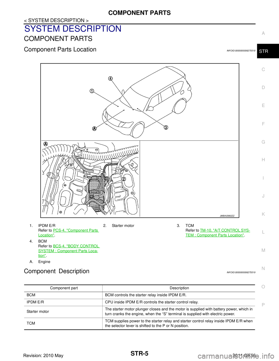
Component Parts LocationINFOID:0000000006275518
Component DescriptionINFOID:0000000006275519
1. IPDM E/R
Refer to PCS-4, "
Component Parts
Location". 2. Starter motor 3. TCM
Refer to TM-10, "
A/T CONTROL SYS-
TEM : Component Parts Location".
4. BCM Refer to BCS-4, "
BODY CONTROL
SYSTEM : Componen t Parts Loca-
tion".
A. Engine
JMBIA2982ZZ
Component part Description
BCM BCM controls the starter relay inside IPDM E/R.
IPDM E/R CPU inside IPDM E/R controls the starter control relay.
Starter motor The starter motor plunger closes and the motor is supplied with battery power, which in
turn cranks the engine, when the “S” terminal is supplied with electric power.
TCM TCM supplies power to the starter relay and starter control relay inside IPDM E/R when
the selector lever is shifted to the P or N position.
Revision: 2010 May2011 QX56
Page 5074 of 5598

STR-6
< SYSTEM DESCRIPTION >
SYSTEM
SYSTEM
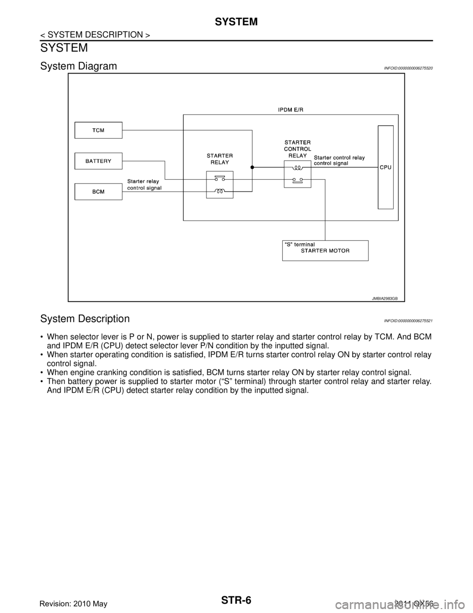
System DiagramINFOID:0000000006275520
System DescriptionINFOID:0000000006275521
When selector lever is P or N, power is supplied to starter relay and starter control relay by TCM. And BCM
and IPDM E/R (CPU) detect selector lever P/N condition by the inputted signal.
When starter operating condition is satisfied, IPDM E/R tu rns starter control relay ON by starter control relay
control signal.
When engine cranking condition is satisfied, BCM turns starter relay ON by starter relay control signal.
Then battery power is supplied to starter motor (“S” terminal) through starter control relay and starter relay. And IPDM E/R (CPU) detect starter re lay condition by the inputted signal.
JMBIA2983GB
Revision: 2010 May2011 QX56
Page 5090 of 5598

TM-2
A/T CONTROL SYSTEM : System Diagram ..........44
A/T CONTROL SYSTEM : System Description ......44
A/T CONTROL SYSTEM : Fail-Safe ......................45
A/T CONTROL SYSTEM : Protection Control ..... ...47
LINE PRESSURE CONTROL ................................ ...48
LINE PRESSURE CONTROL : System Diagram ...48
LINE PRESSURE CONTROL : System Descrip-
tion ....................................................................... ...
48
SHIFT CHANGE CONTROL .................................. ...49
SHIFT CHANGE CONTROL : System Diagram .....50
SHIFT CHANGE CONTROL : System Description
...
50
SHIFT PATTERN CONTROL ................................. ...53
SHIFT PATTERN CONTROL : System Diagram ...54
SHIFT PATTERN CONTROL : System Descrip-
tion ..........................................................................
54
LOCK-UP CONTROL ............................................. ...56
LOCK-UP CONTROL : System Diagram ................56
LOCK-UP CONTROL : System Description ...........56
A/T SHIFT LOCK SYSTEM .......................................57
A/T SHIFT LOCK SYSTEM : System Description ...58
ON BOARD DIAGNOSTIC (OBD) SYSTEM .....60
Diagnosis Description .......................................... ...60
DIAGNOSIS SYSTEM (TCM) ............................61
CONSULT-III Function (TRANSMISSION) .......... ...61
ECU DIAGNOSIS INFORMATION ..............68
TCM ................................................................. ...68
Reference Value .................................................. ...68
Fail-Safe .................................................................74
Protection Control ...................................................76
DTC Inspection Priority Chart .................................77
DTC Index ..............................................................78
WIRING DIAGRAM .....................................80
A/T CONTROL SYSTEM ................................ ...80
Wiring Diagram .................................................... ...80
A/T SHIFT LOCK SYSTEM ...............................85
Wiring Diagram .................................................... ...85
BASIC INSPECTION ...................................88
DIAGNOSIS AND REPAIR WORK FLOW ..... ...88
Diagnosis Flow .................................................... ...88
Question sheet .......................................................89
ADDITIONAL SERVICE WHEN REPLACING
TRANSMISSION ASSEMBLY ...........................
91
Description ........................................................... ...91
Special Repair Requirement ...................................91
ADDITIONAL SERVICE WHEN REPLACING
CONTROL VALVE & TCM ................................
92
Description ........................................................... ...92
Special Repair Requirement ...................................92
CALIBRATION OF DECEL G SENSOR ...........93
Description ........................................................... ...93
Special Repair Requirement ...................................93
A/T FLUID ..........................................................94
Changing .............................................................. ...94
Adjustment ..............................................................95
A/T FLUID COOLER .........................................97
Cleaning ............................................................... ...97
Inspection ................................................................99
STALL TEST ....................................................100
Inspection and Judgment ..................................... .100
A/T POSITION ..................................................101
Inspection ............................................................. .101
Adjustment ............................................................101
DTC/CIRCUIT DIAGNOSIS .......................102
U0300 CAN COMMUNICATION DATA ......... ..102
Description ........................................................... .102
DTC Logic .............................................................102
Diagnosis Procedure .............................................102
U1000 CAN COMM CIRCUIT ...........................103
Description ........................................................... .103
DTC Logic .............................................................103
Diagnosis Procedure .............................................103
P0615 STARTER RELAY .................................104
Description ........................................................... .104
DTC Logic .............................................................104
Diagnosis Procedure .............................................104
P0705 TRANSMISSION RANGE SWITCH A ..106
DTC Logic .............................................................106
Diagnosis Procedure .............................................106
P0710 TRANSMISSION FLUID TEMPERA-
TURE SENSOR A .............................................
107
DTC Logic ............................................................ .107
Diagnosis Procedure .............................................107
P0717 INPUT SPEED SENSOR A ...................109
DTC Logic ............................................................ .109
Diagnosis Procedure .............................................109
P0720 OUTPUT SPEED SENSOR ...................110
DTC Logic ............................................................ .110
Diagnosis Procedure .............................................110
P0725 ENGINE SPEED ....................................112
Description ........................................................... .112
DTC Logic .............................................................112
Diagnosis Procedure .............................................112
P0729 6GR INCORRECT RATIO .....................114
Revision: 2010 May2011 QX56
Page 5099 of 5598
![INFINITI QX56 2011 Factory Service Manual
COMPONENT PARTSTM-11
< SYSTEM DESCRIPTION > [7AT: RE7R01B]
C
EF
G H
I
J
K L
M A
B
TM
N
O P
NOTE:
The following components are included in the control valve & TCM (17).
TCM
Input speed sensor 1, 2
INFINITI QX56 2011 Factory Service Manual
COMPONENT PARTSTM-11
< SYSTEM DESCRIPTION > [7AT: RE7R01B]
C
EF
G H
I
J
K L
M A
B
TM
N
O P
NOTE:
The following components are included in the control valve & TCM (17).
TCM
Input speed sensor 1, 2](/manual-img/42/57033/w960_57033-5098.png)
COMPONENT PARTSTM-11
< SYSTEM DESCRIPTION > [7AT: RE7R01B]
C
EF
G H
I
J
K L
M A
B
TM
N
O P
NOTE:
The following components are included in the control valve & TCM (17).
TCM
Input speed sensor 1, 2
A/T fluid temperature sensor
Transmission range switch
Direct clutch solenoid valve
High and low reverse clutch solenoid valve
Input clutch solenoid valve
Front brake solenoid valve
Low brake solenoid valve
Anti-interlock solenoid valve
2346 brake solenoid valve
Line pressure solenoid valve
Torque converter clutch solenoid valve
A/T CONTROL SYSTEM : Component DescriptionINFOID:0000000006226739
Name Function
TCM TM-12, "
A/T CONTROL SYSTEM : TCM"
Transmission range switchTM-12, "A/T CONTROL SYSTEM : Transmission Range Switch"
Output speed sensor TM-12, "A/T CONTROL SYSTEM : Output Speed Sensor"
Input speed sensor 1
TM-12, "A/T CONTROL SYSTEM : Input Speed Sensor"Input speed sensor 2
A/T fluid temperature sensorTM-12, "
A/T CONTROL SYSTEM : A/T Fluid Temperature Sensor"
Input clutch solenoid valve TM-12, "A/T CONTROL SYSTEM : Input Clutch Solenoid Valve"
Front brake solenoid valve TM-12, "A/T CONTROL SYSTEM : Front Brake Solenoid Valve"
Direct clutch solenoid valveTM-12, "A/T CONTROL SYSTEM : Direct Clutch Solenoid Valve"
High and low reverse clutch solenoid valveTM-13, "A/T CONTROL SYSTEM : High and Low Reverse Clutch Solenoid Valve"
Low brake solenoid valve TM-13, "A/T CONTROL SYSTEM : Low Brake Solenoid Valve"
Anti-interlock solenoid valve TM-13, "A/T CONTROL SYSTEM : Anti-interlock Solenoid Valve"
2346 brake solenoid valve TM-13, "A/T CONTROL SYSTEM : 2346 Brake Solenoid Valve"
Torque converter clutch solenoid valveTM-13, "A/T CONTROL SYSTEM : Torque Converter Clutch Solenoid Valve"
Line pressure solenoid valve TM-13, "A/T CONTROL SYSTEM : Line Pressure Solenoid Valve"
Accelerator pedal position sensor TM-13, "A/T CONTROL SYSTEM : Accelerator Pedal Position Sensor"
Manual mode switch TM-13, "A/T CONTROL SYSTEM : Manual Mode Switch"
Tow mode switch TM-14, "A/T CONTROL SYSTEM : Tow Mode Switch"
A/T CHECK indicator lampTM-14, "A/T CONTROL SYSTEM : A/T CHECK Indicator Lamp"
Tow mode indicator lamp* TM-14, "A/T CONTROL SYSTEM : Tow Mode Indicator Lamp"
Selector lever position indicator TM-14, "A/T CONTROL SYSTEM : Selector Lever Position Indicator"
Stop lamp switch BRC-15, "Stop Lamp Switch"
Yaw rate/side G sensorBRC-15, "Yaw Rate/Side/Decel G sensor"
Starter relay STR-6, "System Description"
ECMEC-35, "ENGINE CONTROL SYSTEM : System Description"
BCM BCS-6, "BODY CONTROL SYSTEM : System Description"
Combination meter MWI-9, "METER SYSTEM : System Description"
ABS actuator and electric unit (control unit) BRC-16, "System Description"
Revision: 2010 May2011 QX56
Page 5132 of 5598
![INFINITI QX56 2011 Factory Service Manual
TM-44
< SYSTEM DESCRIPTION >[7AT: RE7R01B]
SYSTEM
SYSTEM
A/T CONTROL SYSTEM
A/T CONTROL SYSTEM : System DiagramINFOID:0000000006226767
A/T CONTROL SYSTEM : System DescriptionINFOID:0000000006226768
I INFINITI QX56 2011 Factory Service Manual
TM-44
< SYSTEM DESCRIPTION >[7AT: RE7R01B]
SYSTEM
SYSTEM
A/T CONTROL SYSTEM
A/T CONTROL SYSTEM : System DiagramINFOID:0000000006226767
A/T CONTROL SYSTEM : System DescriptionINFOID:0000000006226768
I](/manual-img/42/57033/w960_57033-5131.png)
TM-44
< SYSTEM DESCRIPTION >[7AT: RE7R01B]
SYSTEM
SYSTEM
A/T CONTROL SYSTEM
A/T CONTROL SYSTEM : System DiagramINFOID:0000000006226767
A/T CONTROL SYSTEM : System DescriptionINFOID:0000000006226768
INPUT/OUTPUT SIGNAL CHART
SYSTEM DESCRIPTION
The A/T senses vehicle operating conditions through vari
ous sensors or signals. It always controls the opti-
mum shift position and reduces shifting and lock-up shocks.
Receive input signals transmitted from various switches and sensors.
Determine required line pressure, shifting point, lock-up operation, etc.
JSDIA1853GB
Sensor (or signal)
⇒TCM function
⇒Actuator
Transmission range switch
Accelerator pedal position signal
Closed throttle position signal
Wide open throttle position signal
Engine speed signal
A/T fluid temperature sensor
Output speed sensor
Vehicle speed signal
Manual mode switch signal
Stop lamp switch signal
Input speed sensor 1, 2
Yaw rate/side/decel G sensor
Tow mode switch signal Line pressure control (
TM-48
)
Shift change control ( TM-50
)
Shift pattern control ( TM-54
)
Lock-up control ( TM-56
)
Fail-safe control ( TM-45
)
Self-diagnosis ( TM-61
)
CONSULT-III communication line ( TM-61
)
CAN communication line ( TM-103
)Input clutch solenoid valve
Direct clutch solenoid valve
Front brake solenoid valve
High and low reverse clutch solenoid valve
Low brake solenoid valve
Torque converter clutch solenoid valve
Line pressure solenoid valve
Anti-interlock solenoid valve
2346 brake solenoid valve
A/T CHECK indicator lamp
Tow mode indicator lamp
Shift position indicator
Back-up lamp relay
Starter relay
Revision: 2010 May2011 QX56
Page 5133 of 5598
![INFINITI QX56 2011 Factory Service Manual
SYSTEMTM-45
< SYSTEM DESCRIPTION > [7AT: RE7R01B]
C
EF
G H
I
J
K L
M A
B
TM
N
O P
Transmit required output signals to the respective solenoids.
A/T CONTROL SYSTEM : Fail-SafeINFOID:0000000006226769 INFINITI QX56 2011 Factory Service Manual
SYSTEMTM-45
< SYSTEM DESCRIPTION > [7AT: RE7R01B]
C
EF
G H
I
J
K L
M A
B
TM
N
O P
Transmit required output signals to the respective solenoids.
A/T CONTROL SYSTEM : Fail-SafeINFOID:0000000006226769](/manual-img/42/57033/w960_57033-5132.png)
SYSTEMTM-45
< SYSTEM DESCRIPTION > [7AT: RE7R01B]
C
EF
G H
I
J
K L
M A
B
TM
N
O P
Transmit required output signals to the respective solenoids.
A/T CONTROL SYSTEM : Fail-SafeINFOID:0000000006226769
TCM has the electrical fail-safe mode. The mode is divi ded into a maximum of 3 phases (1st fail-safe, 2nd fail-
safe and final fail-safe) and functions so that the operat ion can be continued even if the signal circuit of the
main electronically controlled input/output parts is damaged.
Even if the electronic circuit is normal, the fail-safe mode may start under special conditions (such as when the
brake pedal is depressed suddenly from a hard wheel spin st atus to stop the rotation of wheels). In this case,
turn the ignition switch OFF and back to ON after 5 seconds to resume the normal shift pattern.
Consequently, the customer's vehicle may already return to the normal condition. Refer to TM-88, "
Diagnosis
Flow".
FAIL-SAFE FUNCTION
1st Fail-SafeThe mode that the vehicle can stop safely, to prompt the driver to stop if the malfunction occurs and to shift to
2nd fail-safe early. It shifts to 2nd fail-safe or final fail-safe after the vehicle stopped.
2nd Fail-Safe The mode that the vehicle shifts to final fail-safe without changing the behavior, by identifying the malfunction-
ing parts in the condition that the driving force required for the driving is secured.
Final Fail-Safe Selects the shifting pattern that the malfunctioning parts identified at 1st fail-safe and 2nd fail-safe are not
used, and then secure the driving force that is required for the driving.
The mode that the shifting performance does not decrease by normal shift control.
DTC Veh ic le
condition Vehicle behavior for 1st fail-safe Vehicle behavior for 2nd fail-safe Vehicle behavior for final fail-safe
P0615 — Starter is disabled — Starter is disabled
P0705 — Fixed in the “D” position (The
shifting can be performed)
30 km/h (19MPH) or less
Lock-up is prohibited
The shifting between the gears of 3 - 4 - 5 - 6 - 7 can be per-
formed
Manual mode is prohibited
Shift position indicator is switched OFF
Starter relay is switched OFF (starter is disabled)
Back-up lamp is OFF
Large shift shock — Fixed in the “D” position (The
shifting can be performed)
30 km/h (19 MPH) or less
Lock-up is prohibited
The shifting between the gears of 3 - 4 - 5 - 6 - 7 can be per-
formed
Manual mode is prohibited
Shift position indicator is switched OFF
Starter relay is switched OFF (starter is disabled)
Back-up lamp is OFF
Large shift shock
P0710 Between
the gears of 1 - 2 - 3 The shifting between the gears
of 1 - 2 - 3 can be performed
Manual mode is prohibited —
The shifting between the gears
of 1 - 2 - 3 can be performed
Manual mode is prohibited
Between
the gears of 4 - 5 - 6 - 7 Fix the gear while driving
Manual mode is prohibited
—
P0717 Between
the gears of
1 - 2 - 3 The shifting between the gears
of 1 - 2 - 3 can be performed
Manual mode is prohibited —
The shifting between the gears
of 1 - 2 - 3 can be performed
Manual mode is prohibited
Between
the gears of 4 - 5 - 6 - 7 Fix the gear while driving
Manual mode is prohibited
—
Revision: 2010 May2011 QX56