2011 INFINITI QX56 radiator
[x] Cancel search: radiatorPage 965 of 5598

SERVICE DATA AND SPECIFICATIONS (SDS)
CO-23
< SERVICE DATA AND SPECIFICATIONS (SDS)
C
D E
F
G H
I
J
K L
M A
CO
NP
O
SERVICE DATA AND SPECIFICATIONS (SDS)
SERVICE DATA AND SPECIFICATIONS (SDS)
Periodical Maintenance SpecificationINFOID:0000000006289675
ENGINE COOLANT CAPACITY (APPROXIMATELY)
Unit: (US qt, Imp qt)
RadiatorINFOID:0000000006289676
Unit: kPa (kg/cm2, psi)
ThermostatINFOID:0000000006289677
Engine coolant capacity [With reservoir tank (“MAX” level)] 14.9 (15-6/8, 13-1/8)
Reservoir tank engine coolant capacity (At “MAX” level) 1.0 (1, 7/8)
Reservoir tank cap relief pressure
Standard 108.2 - 127.8 ( 1.1 - 1.3, 15.7 - 18.5)
Limit 98 (1.0, 14)
Leakage testing pressure 186 (1.9, 27)
ThermostatStandard
Valve opening temperature 82 °C (180 °F)
Maximum valve lift 10.0 mm/95 °C (0.394 in/203 °F)
Valve closing temperature 77 °C (171 °F)
Revision: 2010 May2011 QX56
Page 1542 of 5598

DLK-6
HAZARD WARNING LAMP : Diagnosis Proce-
dure .......................................................................
204
AUTOMATIC BACK DOOR FUNCTIONS DO
NOT CANCEL ................................................. .
206
Diagnosis Procedure ........................................... ..206
AUTOMATIC BACK DOOR ANTI-PINCH
FUNCTION DOES NOT OPERATE .................
207
Diagnosis Procedure ........................................... ..207
INTEGRATED HOMELINK TRANSMITTER
DOES NOT OPERATE ....................................
208
Diagnosis Procedure ........................................... ..208
SQUEAK AND RATTLE TROUBLE DIAG-
NOSES .............................................................
209
Work Flow ............................................................ ..209
Inspection Procedure .............................................211
Diagnostic Worksheet ............................................213
REMOVAL AND INSTALLATION ..............215
HOOD .............................................................. .215
Exploded View ..................................................... ..215
HOOD ASSEMBLY ................................................ ..215
HOOD ASSEMBLY : Removal and Installation .....215
HOOD ASSEMBLY : Adjustme nt ........................ ..216
HOOD HINGE ......................................................... ..218
HOOD HINGE : Removal and Installation .............218
HOOD STAY .......................................................... ..218
HOOD STAY : Removal and Installation ...............218
HOOD STAY : Disposal .........................................218
RADIATOR CORE SUPPORT .........................220
Exploded View ..................................................... ..220
Removal and Installation .......................................220
FRONT FENDER .............................................222
Exploded View ..................................................... ..222
FRONT FENDER .................................................... ..222
FRONT FENDER : Removal and Installation ........222
FRONT FENDER DRIP COVER ............................ ..223
FRONT FENDER DRIP COVER : Removal and
Installation .............................................................
223
FRONT FENDER DUCT ......................................... ..223
FRONT FENDER DUCT : Removal and Installa-
tion .........................................................................
223
FRONT DOOR .................................................224
Exploded View ..................................................... ..224
DOOR ASSEMBLY ................................................ ..224
DOOR ASSEMBLY : Removal and Installation .....224
DOOR ASSEMBLY : Adjustme nt ........................ ..225
DOOR STRIKER .................................................... ..226
DOOR STRIKER : Removal and Installation ........226
DOOR HINGE ......................................................... .226
DOOR HINGE : Removal and Installation ............226
DOOR CHECK LINK .............................................. .226
DOOR CHECK LINK : Removal and Installation ..226
REAR DOOR ....................................................228
Exploded View ..................................................... .228
DOOR ASSEMBLY .................................................228
DOOR ASSEMBLY : Removal and Installation ....228
DOOR ASSEMBLY : Adjustme nt ..........................229
DOOR STRIKER .................................................... .230
DOOR STRIKER : Removal and Installation ........230
DOOR HINGE ......................................................... .230
DOOR HINGE : Removal and Installation ............230
DOOR CHECK LINK .............................................. .230
DOOR CHECK LINK : Removal and Installation ..230
BACK DOOR .................................................. ..232
Exploded View ..................................................... .232
BACK DOOR ASSEMBLY ......................................232
BACK DOOR ASSEMBLY : Removal and Installa-
tion ....................................................................... .
232
BACK DOOR ASSEMBLY : Adjustment ...............234
BACK DOOR STRIKER ......................................... .235
BACK DOOR STRIKER : Removal and Installa-
tion ........................................................................
235
BACK DOOR HINGE ............................................. .236
BACK DOOR HINGE : Removal and Installation ..236
BACK DOOR STAY ............................................... .236
BACK DOOR STAY : Removal and Installation ....236
BACK DOOR STAY : Disposal ............................ .237
BACK DOOR WEATHER-STRIP ........................... .237
BACK DOOR WEATHER-STRIP : Removal and
Installation .............................................................
237
HOOD LOCK ....................................................238
Exploded View ..................................................... .238
Removal and Installation .......................................238
Inspection ..............................................................239
FRONT DOOR LOCK .......................................240
Exploded View ..................................................... .240
DOOR LOCK .......................................................... .240
DOOR LOCK : Removal and Installation ..............240
INSIDE HANDLE .................................................... .241
INSIDE HANDLE : Removal and Installation ........241
OUTSIDE HANDLE ................................................ .241
OUTSIDE HANDLE : Removal and Installation ....241
REAR DOOR LOCK .........................................243
Revision: 2010 May2011 QX56
Page 1748 of 5598

DLK-212
< SYMPTOM DIAGNOSIS >
SQUEAK AND RATTLE TROUBLE DIAGNOSES
Most of these incidents can be repaired by adjusting, securing or insulating the item(s) or component(s) caus-
ing the noise.
SUNROOF/HEADLINING
Noises in the sunroof/headlining area c an often be traced to one of the following:
1. Sunroof lid, rail, linkage or seals making a rattle or light knocking noise
2. Sunvisor shaft shaking in the holder
3. Front or rear windshield touching headlining and squeaking
Again, pressing on the components to stop the noise while duplicating the conditions can isolate most of these
incidents. Repairs usually consist of insulating with felt cloth tape.
SEATS
When isolating seat noise it is important to note t he position the seat is in and the load placed on the seat
when the noise is present. These conditions should be duplicated when verifying and isolating the cause of
the noise.
Cause of seat noise include:
1. Headrest rods and holder
2. A squeak between the seat pad cushion and frame
3. Rear seatback lock and bracket
These noises can be isolated by moving or pressing on the suspected components while duplicating the con-
ditions under which the noise occurs. Most of thes e incidents can be repaired by repositioning the component
or applying urethane tape to the contact area.
UNDERHOOD
Some interior noise may be caused by components under the hood or on the engine wall. The noise is then
transmitted into the passenger compartment.
Causes of transmitted underhood noise include:
1. Any component mounted to the engine wall
2. Components that pass through the engine wall
3. Engine wall mounts and connectors
4. Loose radiator mounting pins
5. Hood bumpers out of adjustment
6. Hood striker out of adjustment
These noises can be difficult to isolate since they cannot be reached from the interior of the vehicle. The best
method is to secure, move or insulate one component at a time and test drive the \
vehicle. Also, engine RPM
or load can be changed to isolate the noise. Repairs can usually be made by moving, adjusting, securing, or
insulating the component causing the noise.
Revision: 2010 May2011 QX56
Page 1751 of 5598

HOOD
DLK-215
< REMOVAL AND INSTALLATION >
C
D E
F
G H
I
J
L
M A
B
DLK
N
O P
REMOVAL AND INSTALLATION
HOOD
Exploded ViewINFOID:0000000006226062
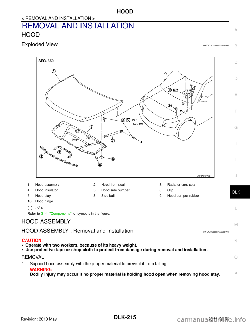
HOOD ASSEMBLY
HOOD ASSEMBLY : Removal and InstallationINFOID:0000000006226063
CAUTION:
Operate with two workers, because of its heavy weight.
Use protective tape or shop cloth to protect from damage during removal and installation.
REMOVAL
1. Support hood assembly with the proper material to prevent it from falling.
WARNING:
Bodily injury may occur if no proper material is holding hood open when removing hood stay.
1. Hood assembly 2. Hood front seal 3. Radiator core seal
4. Hood insulator 5. Hood side bumper 6. Clip
7. Hood stay 8. Stud ball 9. Hood bumper rubber
10. Hood hinge
: Clip
Refer to GI-4, "
Components" for symbols in the figure.
JMKIA5477GB
Revision: 2010 May2011 QX56
Page 1756 of 5598

DLK-220
< REMOVAL AND INSTALLATION >
RADIATOR CORE SUPPORT
RADIATOR CORE SUPPORT
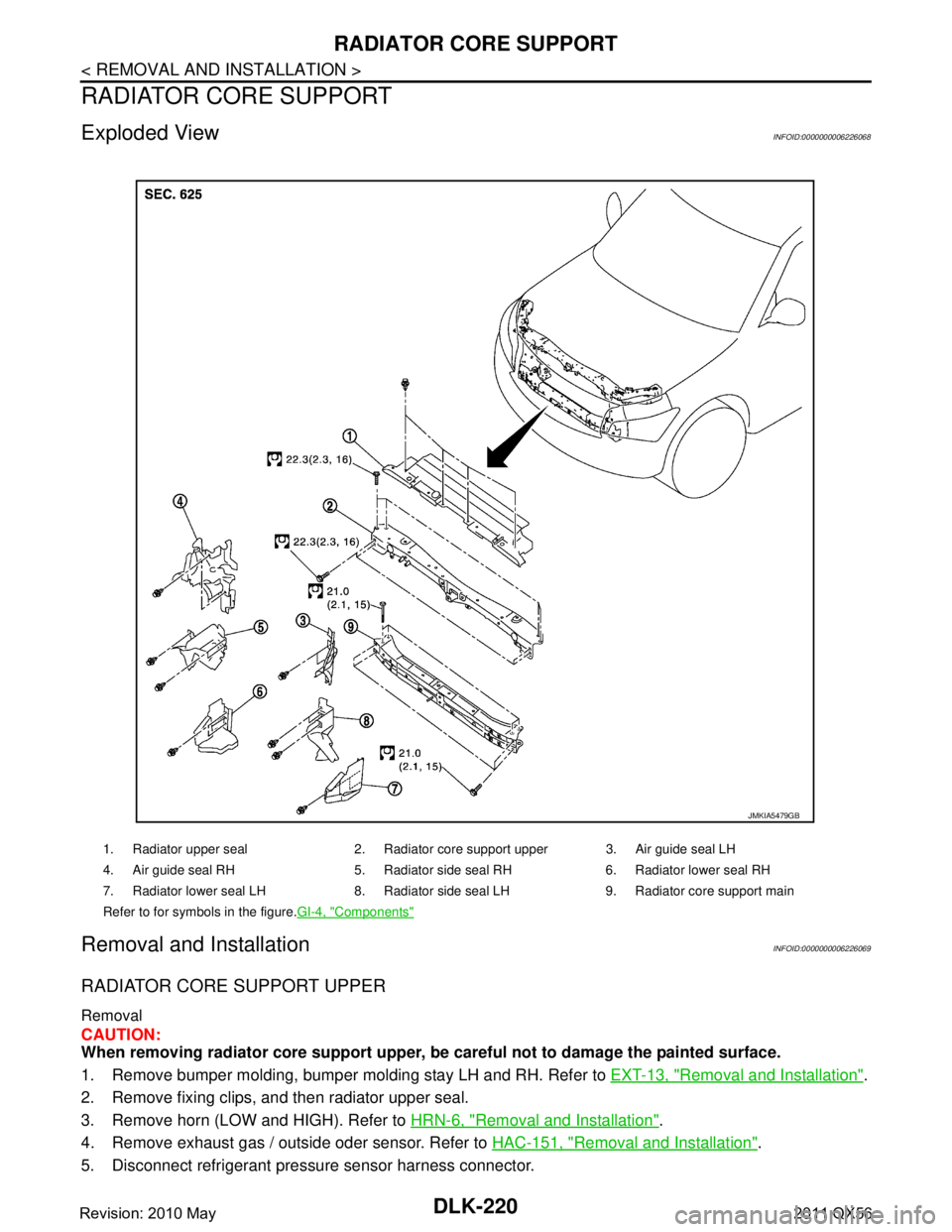
Exploded ViewINFOID:0000000006226068
Removal and InstallationINFOID:0000000006226069
RADIATOR CORE SUPPORT UPPER
Removal
CAUTION:
When removing radiator core support upper, be careful not to damage the painted surface.
1. Remove bumper molding, bumper molding stay LH and RH. Refer to EXT-13, "
Removal and Installation".
2. Remove fixing clips, and then radiator upper seal.
3. Remove horn (LOW and HIGH). Refer to HRN-6, "
Removal and Installation".
4. Remove exhaust gas / outside oder sensor. Refer to HAC-151, "
Removal and Installation".
5. Disconnect refrigerant pressu re sensor harness connector.
1. Radiator upper seal 2. Radiator core support upper 3. Air guide seal LH
4. Air guide seal RH 5. Radiator side seal RH 6. Radiator lower seal RH
7. Radiator lower seal LH 8. Radiator side seal LH 9. Radiator core support main
Refer to for symbols in the figure.GI-4, "
Components"
JMKIA5479GB
Revision: 2010 May2011 QX56
Page 1757 of 5598

RADIATOR CORE SUPPORTDLK-221
< REMOVAL AND INSTALLATION >
C
DE
F
G H
I
J
L
M A
B
DLK
N
O P
6. Disconnect all harness clips.
7. Remove hood lock assembly. Refer to DLK-238, "
Removal and Installation".
8. Remove fixing clips of air guide seal.
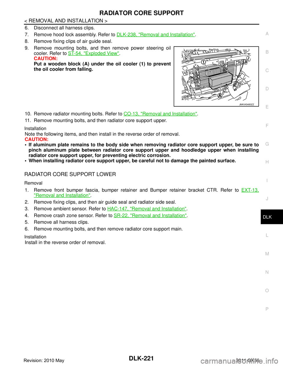
9. Remove mounting bolts, and then remove power steering oil cooler. Refer to ST-54, "
Exploded View".
CAUTION:
Put a wooden block (A) under the oil cooler (1) to prevent
the oil cooler from falling.
10. Remove radiator mounting bolts. Refer to CO-13, "
Removal and Installation".
11. Remove mounting bolts, and then radiator core support upper.
Installation
Note the following items, and then install in the reverse order of removal.
CAUTION:
If aluminum plate remains to the body side when removing radiator core support upper, be sure to
pinch aluminum plate between radiator core support upper and hoodledge upper when installing
radiator core support upper, for preventing electric corrosion.
When installing radiator core support upper, be careful not to damage the painted surface.
RADIATOR CORE SUPPORT LOWER
Removal
1. Remove front bumper fascia, bumper retainer and Bumper retainer bracket CTR. Refer to EXT-13,
"Removal and Installation".
2. Remove fixing clips, and then air guide seal and radiator side seal.
3. Remove ambient sensor. Refer to HAC-147, "
Removal and Installation".
4. Remove crash zone sensor. Refer to SR-22, "
Removal and Installation".
5. Remove all harness clips.
6. Remove mounting bolts, and then remove radiator core support main.
Installation
Install in the reverse order of removal.
JMKIA5480ZZ
Revision: 2010 May2011 QX56
Page 1788 of 5598

DLK-252
< REMOVAL AND INSTALLATION >
CAB MOUNTING INSULATOR
Drain brake fluid from brake line. Refer to BR-10, "Draining".
Release fuel pressure. Refer to EC-153, "
Work Procedure".
Disconnect both battery cables. Refer to PG-164, "
Removal and Installation".
Drain engine coolant from radiator. Refer to CO-8, "
Draining".
Discharge refrigerant from A/C circuit. Refer to HA-20, "
Recycle Refrigerant".
Drain power steering fluid from reservoir tank.
4. Remove parts relating to connection of body assembly and frame assembly. Tire and wheel: Refer to WT-64, "
Removal and Installation" (with TPMS).
Front fender protector (LH and RH): Refer to EXT-23, "
FENDER PROTECTOR : Removal and Installa-
tion".
Front bumper: Refer to EXT-13, "
Removal and Installation".
Radiator core support upper: Refer to DLK-220, "
Removal and Installation".
Fan shroud: Refer to CO-16, "
Removal and Installation".
Battery and battery case: Refer to PG-164, "
Removal and Installation".
Air cleaner case (upper and lower): Refer to EM-27, "
Removal and Installation".
Engine cover: Refer to EM-25, "
Removal and Installation".
Rear wheel house protector (LH and RH): EXT-24, "
REAR WHEEL HOUSE PROTECTOR : Removal
and Installation".
Rear bumper: Refer to EXT-17, "
Removal and Installation".
Fuel filler tube: Remove to FL-8, "
Exploded View".
Spare tire
Towing hook bracket.
5. Separate parts relating to connection of body assembly and frame assembly. Vehicle front
Disconnect ICC sensor connector. (models with ICC) Refer to CCS-176, "
Removal and Installation".
Remove radiator upper hose and radiator lower hose from radiator assembly. Refer to CO-13,
"Exploded View".
Remove A/T fluid cooler hose B and A/T fluid cooler hose E from A/T fluid cooler tubes. Refer to TM-
202, "Exploded View".
Remove power steering return hose from oil cooler, and then power steering return hose clamp bolt from frame assembly. Refer to ST-54, "
Exploded View".
Remove power steering suction hose from reservoir tank. Refer to ST-54, "
Exploded View".
CAUTION:
Never spill power steering fluid in engine room.
Remove A/C low-presser flexible hose from A/C low-presser pipe. Refer to HA-35, "
LOW-PRESSURE
FLEXIBLE HOSE : Removal and Installation".
Remove A/C hi-presser flexible hose from condenser. Refer to HA-34, "
HIGH-PRESSURE FLEXIBLE
HOSE : Removal and Installation".
Remove all engine Control Harness connectors, har ness clips and others that are connected to the
body assembly side of the engine room. (engine room LH and RH side). Refer to PG-148, "
Engine Con-
trol Harness".
NOTE:
Separate harness connectors from ECM (engine control module). Refer to EC-10, "
General Precau-
tions".
CAUTION:
When pulling out harnesses, never damage harnesses or connectors.
After temporarily securing connectors, cover th em with vinyl or similar material to protect
against adhesion of foreign materials.
Disconnect engine room harness connectors and remo ve harness clips from engine assembly (engine
RH side). Refer to PG-146, "
Engine Room Harness".
Remove heater hoses from front water outlet tube (engine room RH side). Refer to HA-33, "
Exploded
View".
Disconnect front wheel sensor connectors (LH and RH). Refer to BRC-134, "
FRONT WHEEL SENSOR
: Exploded View".
Disconnect fuel feed tube and EVAP hos e (front wheel well LH side).
Remove steering lower shaft from steering gear side assembly. Refer to ST-37, "
Removal and Installa-
tion"
CAUTION:
Spiral cable may be cut if steering wheel turns while separating steering column assembly and
steering gear assembly.
Revision: 2010 May2011 QX56
Page 2247 of 5598
![INFINITI QX56 2011 Factory Service Manual
P0125 ECT SENSOREC-223
< DTC/CIRCUIT DIAGNOSIS > [VK56VD]
C
D
E
F
G H
I
J
K L
M A
EC
NP
O
NO >> Replace engine coolant temperature sensor.
2.CHECK THERMOSTAT OPERATION
When the engine is cold [lower INFINITI QX56 2011 Factory Service Manual
P0125 ECT SENSOREC-223
< DTC/CIRCUIT DIAGNOSIS > [VK56VD]
C
D
E
F
G H
I
J
K L
M A
EC
NP
O
NO >> Replace engine coolant temperature sensor.
2.CHECK THERMOSTAT OPERATION
When the engine is cold [lower](/manual-img/42/57033/w960_57033-2246.png)
P0125 ECT SENSOREC-223
< DTC/CIRCUIT DIAGNOSIS > [VK56VD]
C
D
E
F
G H
I
J
K L
M A
EC
NP
O
NO >> Replace engine coolant temperature sensor.
2.CHECK THERMOSTAT OPERATION
When the engine is cold [lower than 70 °C (158 °F)] condition, grasp lower radiator hose and confirm that the
engine coolant does not flow.
Is the inspection result normal?
YES >> GO TO 3.
NO >> Repair or replace thermostat. Refer to CO-20, "
Removal and Installation".
3.CHECK INTERMITTENT INCIDENT
Refer to GI-40, "
Intermittent Incident".
>> INSPECTION END
Component Inspection (Engine Coolant Temperature Sensor)INFOID:0000000006288610
1.CHECK ENGINE COOLANT TEMPERATURE SENSOR
1. Turn ignition switch OFF.
2. Disconnect engine coolant temperature sensor harness connector.
3. Remove engine coolant temperature sensor.
4. Check resistance between engine coolant temperature sensor
terminals by heating with hot water as shown in the figure.
Is the inspection result normal?
YES >> INSPECTION END
NO >> Replace engine coolant temperature sensor. Refer to EM-86, "
Exploded View".
Terminals Condition Resistance (k Ω)
1 and 2 Temperature [ °C ( °F)] 20 (68) 2.35 - 2.73
50 (122) 0.68 - 1.00
90 (194) 0.236 - 0.260
JMBIA0080ZZ
Revision: 2010 May2011 QX56