2011 INFINITI QX56 wheel
[x] Cancel search: wheelPage 3702 of 5598
MA-32
< PERIODIC MAINTENANCE >
CHASSIS MAINTENANCE
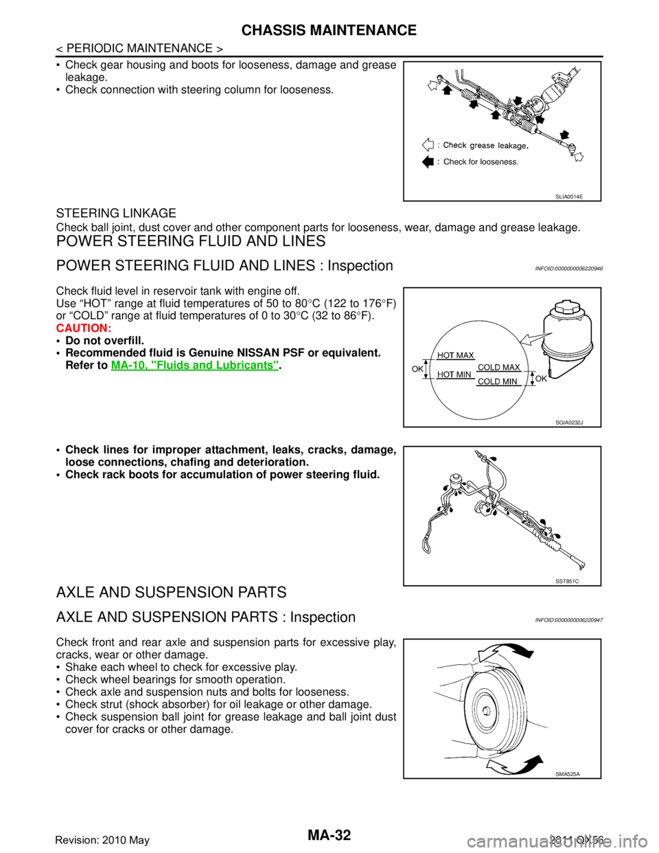
Check gear housing and boots for looseness, damage and greaseleakage.
Check connection with steering column for looseness.
STEERING LINKAGE
Check ball joint, dust cover and other component parts for looseness, wear, damage and grease leakage.
POWER STEERING FLUID AND LINES
POWER STEERING FLUID AND LINES : InspectionINFOID:0000000006220946
Check fluid level in reservoir tank with engine off.
Use “HOT” range at fluid temperatures of 50 to 80 °C (122 to 176 °F)
or “COLD” range at fluid temperatures of 0 to 30 °C (32 to 86 °F).
CAUTION:
Do not overfill.
Recommended fluid is Genuine NISSAN PSF or equivalent.
Refer to MA-10, "
Fluids and Lubricants".
Check lines for improper attachment, leaks, cracks, damage, loose connections, chaf ing and deterioration.
Check rack boots for accumulati on of power steering fluid.
AXLE AND SUSPENSION PARTS
AXLE AND SUSPENSION PARTS : InspectionINFOID:0000000006220947
Check front and rear axle and suspension parts for excessive play,
cracks, wear or other damage.
Shake each wheel to check for excessive play.
Check wheel bearings for smooth operation.
Check axle and suspension nuts and bolts for looseness.
Check strut (shock absorber) for oil leakage or other damage.
Check suspension ball joint for grease leakage and ball joint dust
cover for cracks or other damage.
SLIA0014E
SGIA0232J
SST851C
SMA525A
Revision: 2010 May2011 QX56
Page 3705 of 5598
SERVICE DATA AND SPECIFICATIONS (SDS)
MA-35
< SERVICE DATA AND SPECIFICATIONS (SDS)
C
D E
F
G H
I
J
K L
M B
MA
N
O A
SERVICE DATA AND SPECIFICATIONS (SDS)
SERVICE DATA AND SPECIFICATIONS (SDS)
DRIVE BELTS
DRIVE BELTS : Drive BeltsINFOID:0000000006394853
DRIVE BELT
ENGINE COOLANT
ENGINE COOLANT : Periodical Maintenance SpecificationINFOID:0000000006394856
ENGINE COOLANT CAPACITY (APPROXIMATELY)
Unit: (US qt, Imp qt)
ENGINE OIL
ENGINE OIL : Periodical Maintenance SpecificationINFOID:0000000006394855
ENGINE OIL CAPACITY (APPROXIMATE)
Unit: (US qt, Imp qt)
SPARK PLUG
SPARK PLUG : Spark PlugINFOID:0000000006394854
SPARK PLUG
Unit: mm (in)
ROAD WHEEL
ROAD WHEEL : Road WheelINFOID:0000000006349771
ALUMINUM WHEEL
Tension of drive belts Belt tension is not necessary, as it is automatically adjusted by drive belt auto-tensioner.
Engine coolant capacity [With reservoir tank (“MAX” level)] 14.9 (15-6/8, 13-1/8)
Reservoir tank engine coolant capacity (At “MAX” level) 1.0 (1, 7/8)
Drain and refill
With oil filter change 6.5 (6-7/8, 5-3/4)
Without oil filter change 6.2 (6-4/8, 5-1/2)
Dry engine (engine overhaul) 7.6 (8, 6-3/4)
Make NGK
Standard type DILKAR7B11
Gap Standard 1.1 (0.043)
Limit 1.25 (0.049)
Item Limit
Radial runout Lateral deflection
Less than 0.3 mm (0.012 in)
Vertical deflection
Allowable unbalance Dynamic (At flange) Less than 7 g (0.25 oz) (one side)
Static (At flange) Less than 14 g (0.49 oz)
Revision: 2010 May2011 QX56
Page 3706 of 5598

MIR-1
DRIVER CONTROLS
C
DE
F
G H
I
J
K
M
SECTION MIR
A
B
MIR
N
O P
CONTENTS
MIRRORS
PRECAUTION ................ ...............................3
PRECAUTIONS .............................................. .....3
Precaution for Supplemental Restraint System
(SRS) "AIR BAG" and "SEAT BELT PRE-TEN-
SIONER" ............................................................. ......
3
Precaution Necessary for Steering Wheel Rota-
tion after Battery Disconnect .....................................
3
PREPARATION ............................................5
PREPARATION .............................................. .....5
Commercial Service Tools ................................. ......5
SYSTEM DESCRIPTION ..............................6
COMPONENT PARTS ................................... .....6
DOOR MIRROR ..................................................... ......6
DOOR MIRROR : Component Parts Location ..........6
DOOR MIRROR : Component Description ...............6
INSIDE MIRROR .................................................... ......7
INSIDE MIRROR : Component Description ..............7
SYSTEM ..............................................................8
DOOR MIRROR SYSTEM ..................................... ......8
DOOR MIRROR SYSTEM : System Diagram ..........8
DOOR MIRROR SYSTEM : System Description ......8
AUTO ANTI-DAZZLING INSIDE MIRROR SYS-
TEM ........................................................................ ......
9
AUTO ANTI-DAZZLING INSIDE MIRROR SYS-
TEM : System Description .........................................
9
ECU DIAGNOSIS INFORMATION ..............10
DRIVER SEAT CONTROL UNIT, AUTOMAT-
IC DRIVE POSITIONER CONTROL UNIT ..... ....
10
List of ECU Reference ........................................ ....10
WIRING DIAGRAM ......................................11
DOOR MIRROR SYSTEM .................................11
Wiring Diagram .................................................... ....11
AUTO ANTI-DAZZLING INSIDE MIRROR
SYSTEM ............................................................
19
Wiring Diagram - INSIDE MIRROR SYSTEM - ... ....19
BASIC INSPECTION ....... ............................21
DIAGNOSIS AND REPAIR WORKFLOW ........21
Work Flow ............................................................ ....21
DTC/CIRCUIT DIAGNOSIS .........................22
DOOR MIRROR REMOTE CONTROL
SWITCH .............................................................
22
OPEN/CLOSE SWITCH ......................................... ....22
OPEN/CLOSE SWITCH : Component Inspection ....22
SYMPTOM DIAGNOSIS ..............................23
REVERSE INTERLOCK DOOR MIRROR
DOES NOT OPERATE ......................................
23
Diagnosis Procedure ........................................... ....23
SQUEAK AND RATTLE TROUBLE DIAG-
NOSES ..............................................................
24
Work Flow ................................................................24
Inspection Procedure ...............................................26
Diagnostic Worksheet ..............................................28
REMOVAL AND INSTALLATION ...............30
INSIDE MIRROR ...............................................30
Exploded View ..................................................... ....30
Removal and Installation .........................................30
OUTSIDE MIRROR ...........................................32
Exploded View .........................................................32
DOOR MIRROR ASSEMBLY ....................................32
Revision: 2010 May2011 QX56
Page 3708 of 5598
PRECAUTIONSMIR-3
< PRECAUTION >
C
DE
F
G H
I
J
K
M A
B
MIR
N
O P
PRECAUTION
PRECAUTIONS
Precaution for Supplemental Restraint System (SRS) "AIR BAG" and "SEAT BELT
PRE-TENSIONER"
INFOID:0000000006257245
The Supplemental Restraint System such as “A IR BAG” and “SEAT BELT PRE-TENSIONER”, used along
with a front seat belt, helps to reduce the risk or severi ty of injury to the driver and front passenger for certain
types of collision. This system includes seat belt switch inputs and dual stage front air bag modules. The SRS
system uses the seat belt switches to determine the front air bag deployment, and may only deploy one front
air bag, depending on the severity of a collision and whether the front occupants are belted or unbelted.
Information necessary to service the system safely is included in the “SRS AIR BAG” and “SEAT BELT” of this
Service Manual.
WARNING:
• To avoid rendering the SRS inoper ative, which could increase the risk of personal injury or death in
the event of a collision that would result in air ba g inflation, all maintenance must be performed by
an authorized NISSAN/INFINITI dealer.
Improper maintenance, including in correct removal and installation of the SRS, can lead to personal
injury caused by unintentional act ivation of the system. For removal of Spiral Cable and Air Bag
Module, see the “SRS AIR BAG”.
Do not use electrical test equipm ent on any circuit related to the SRS unless instructed to in this
Service Manual. SRS wiring harnesses can be identi fied by yellow and/or orange harnesses or har-
ness connectors.
PRECAUTIONS WHEN USING POWER TOOLS (AIR OR ELECTRIC) AND HAMMERS
WARNING:
When working near the Air Bag Diagnosis Sensor Unit or other Air Bag System sensors with the
ignition ON or engine running, DO NOT use air or electric power tools or strike near the sensor(s)
with a hammer. Heavy vibration could activate the sensor(s) and deploy the air bag(s), possibly
causing serious injury.
When using air or electric power tools or hammers , always switch the ignition OFF, disconnect the
battery, and wait at least 3 minutes before performing any service.
Precaution Necessary for Steering Wh eel Rotation after Battery Disconnect
INFOID:0000000006257246
NOTE:
Before removing and installing any control units, first tu rn the push-button ignition switch to the LOCK posi-
tion, then disconnect both battery cables.
After finishing work, confirm that all control unit connectors are connected properly, then re-connect both
battery cables.
Always use CONSULT-III to perform self-diagnosis as a part of each function inspection after finishing work.
If a DTC is detected, perform trouble diagnos is according to self-diagnosis results.
For vehicle with steering lock unit, if the battery is disconnected or discharged, the steering wheel will lock and
cannot be turned.
If turning the steering wheel is required with the batte ry disconnected or discharged, follow the operation pro-
cedure below before starting the repair operation.
OPERATION PROCEDURE
1. Connect both battery cables. NOTE:
Supply power using jumper cables if battery is discharged.
2. Turn the push-button ignition switch to ACC position. (At this time, the steering lock will be released.)
3. Disconnect both battery cables. The steering lock wil l remain released with both battery cables discon-
nected and the steering wheel can be turned.
4. Perform the necessary repair operation.
Revision: 2010 May2011 QX56
Page 3709 of 5598

MIR-4
< PRECAUTION >
PRECAUTIONS
5. When the repair work is completed, re-connect both battery cables. With the brake pedal released, turn
the push-button ignition switch from ACC position to ON position, then to LOCK position. (The steering
wheel will lock when the push-button igniti on switch is turned to LOCK position.)
6. Perform self-diagnosis check of all control units using CONSULT-III.
Revision: 2010 May2011 QX56
Page 3756 of 5598
MWI
SYSTEMMWI-13
< SYSTEM DESCRIPTION >
C
DE
F
G H
I
J
K L
M B A
O P
SPEEDOMETER
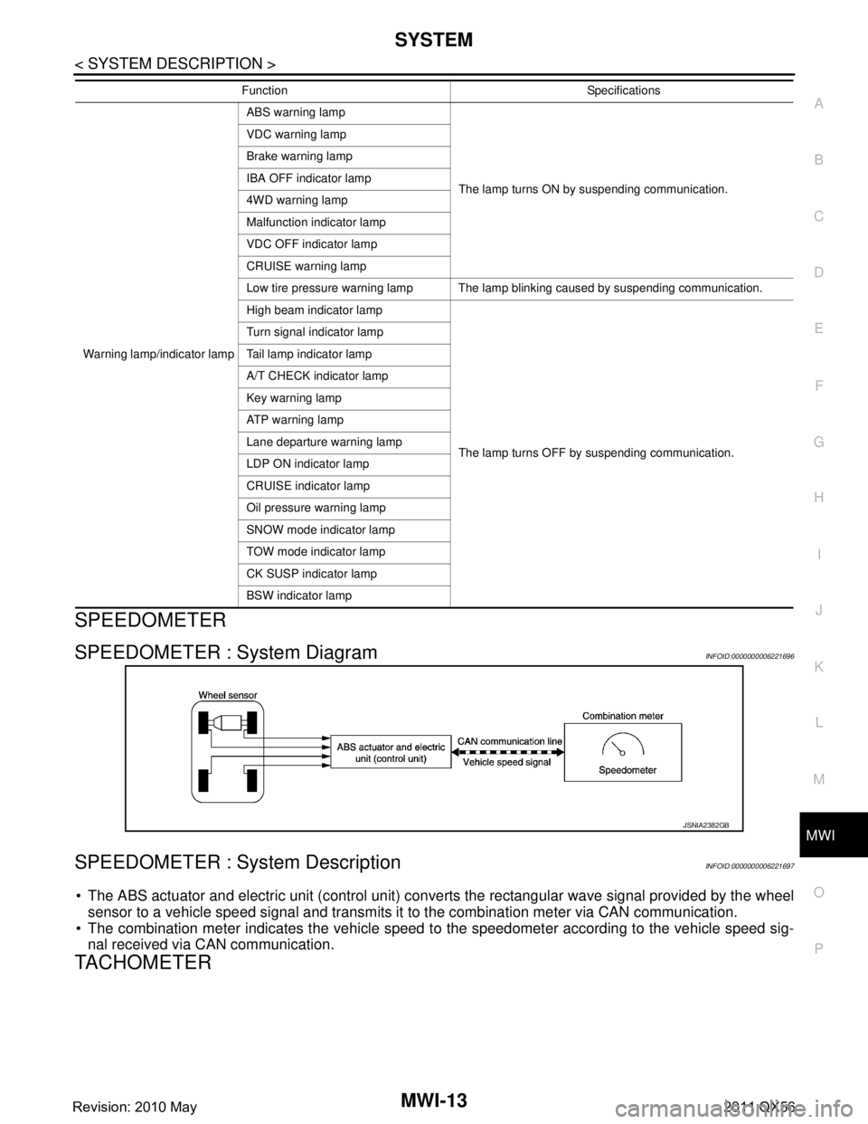
SPEEDOMETER : System DiagramINFOID:0000000006221696
SPEEDOMETER : System DescriptionINFOID:0000000006221697
The ABS actuator and electric unit (control unit) conv erts the rectangular wave signal provided by the wheel
sensor to a vehicle speed signal and transmits it to the combination meter via CAN communication.
The combination meter indicates the vehicle speed to the speedometer according to the vehicle speed sig-
nal received via CAN communication.
TACHOMETER
Warning lamp/indicator lamp ABS warning lamp
The lamp turns ON by suspending communication.
VDC warning lamp
Brake warning lamp
IBA OFF indicator lamp
4WD warning lamp
Malfunction indicator lamp
VDC OFF indicator lamp
CRUISE warning lamp
Low tire pressure warning lamp The lamp blinking caused by suspending communication.
High beam indicator lamp
The lamp turns OFF by suspending communication.
Turn signal indicator lamp
Tail lamp indicator lamp
A/T CHECK indicator lamp
Key warning lamp
AT P w a r n i n g l a m p
Lane departure warning lamp
LDP ON indicator lamp
CRUISE indicator lamp
Oil pressure warning lamp
SNOW mode indicator lamp
TOW mode indicator lamp
CK SUSP indicator lamp
BSW indicator lamp
Function Specifications
JSNIA2382GB
Revision: 2010 May2011 QX56
Page 3763 of 5598
MWI-20
< SYSTEM DESCRIPTION >
SYSTEM
INFORMATION DISPLAY : System Description
INFOID:0000000006221717
DESCRIPTION
The combination meter receives signals necessary for controlling the operation of the information display from each unit, sensor and switch.
The combination meter incorporates a trip computer t hat displays the warning/information according to the
information received from each unit, sensor and switch.
The combination meter shows the following functions on the information display.
- Odo/trip meter
- Shift position indicator
- Trip computer
- Interrupt indication
- Warning check indication
- Setting
ODO/TRIP METER
The ABS actuator and electric unit (control unit) r eads the rectangular wave signal provided by the wheel
sensor and transmits the vehicle speed signal to the combination meter via CAN communication.
The combination meter converts the vehicle speed signal received via CAN communication to mileage, and it displays the accumulated mileage on the information display.
SHIFT POSITION INDICATOR
MANUAL MODE
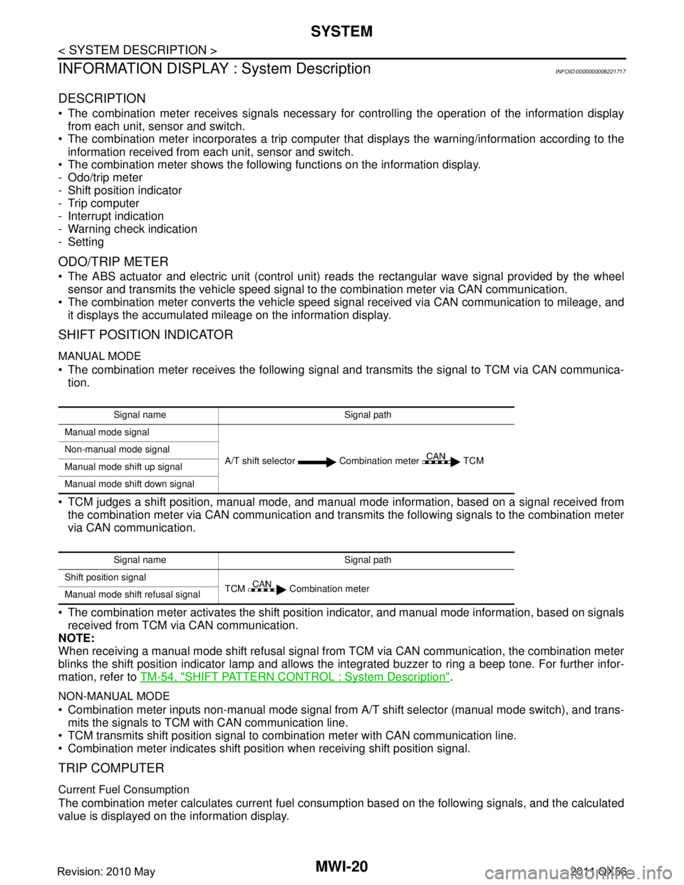
The combination meter receives the following signal and transmits the signal to TCM via CAN communica-tion.
TCM judges a shift position, manual mode, and manual mode information, based on a signal received from
the combination meter via CAN communication and transmi ts the following signals to the combination meter
via CAN communication.
The combination meter activates the shift position indicator, and manual mode information, based on signals received from TCM via CAN communication.
NOTE:
When receiving a manual mode shift refusal signal from TCM via CAN communication, the combination meter
blinks the shift position indicator lamp and allows the integrated buzzer to ring a beep tone. For further infor-
mation, refer to TM-54, "
SHIFT PATTERN CONTROL : System Description".
NON-MANUAL MODE
Combination meter inputs non-manual mode signal from A/T shift selector (manual mode switch), and trans-
mits the signals to TCM with CAN communication line.
TCM transmits shift position signal to combination meter with CAN communication line.
Combination meter indicates shift position when receiving shift position signal.
TRIP COMPUTER
Current Fuel Consumption
The combination meter calculates current fuel cons umption based on the following signals, and the calculated
value is displayed on the information display.
Signal name Signal path
Manual mode signal
A/T shift selector Combination meter TCM
Non-manual mode signal
Manual mode shift up signal
Manual mode shift down signal
Signal name Signal path
Shift position signal TCM Combination meter
Manual mode shift refusal signal
Revision: 2010 May2011 QX56
Page 3804 of 5598
MWI
B2205 VEHICLE SPEEDMWI-61
< DTC/CIRCUIT DIAGNOSIS >
C
DE
F
G H
I
J
K L
M B A
O P
B2205 VEHICLE SPEED
DescriptionINFOID:0000000006221734
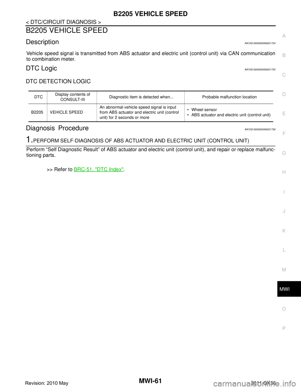
Vehicle speed signal is transmitted from ABS actuator and electric unit (control unit) via CAN communication
to combination meter.
DTC LogicINFOID:0000000006221735
DTC DETECTION LOGIC
Diagnosis ProcedureINFOID:0000000006221736
1.PERFORM SELF-DIAGNOSIS OF ABS ACTUAT OR AND ELECTRIC UNIT (CONTROL UNIT)
Perform “Self Diagnostic Result” of ABS actuator and electric unit (control unit), and repair or replace malfunc-
tioning parts.
>> Refer to BRC-51, "
DTC Index".
DTCDisplay contents of
CONSULT-III Diagnostic item is detected when... Probable malfunction location
B2205 VEHICLE SPEED An abnormal vehicle speed signal is input
from ABS actuator and electric unit (control
unit) for 2 seconds or more Wheel sensor
ABS actuator and electric
unit (control unit)
Revision: 2010 May2011 QX56