2011 INFINITI QX56 wheel
[x] Cancel search: wheelPage 2956 of 5598
FSU-14
< REMOVAL AND INSTALLATION >
LOWER LINK
LOWER LINK
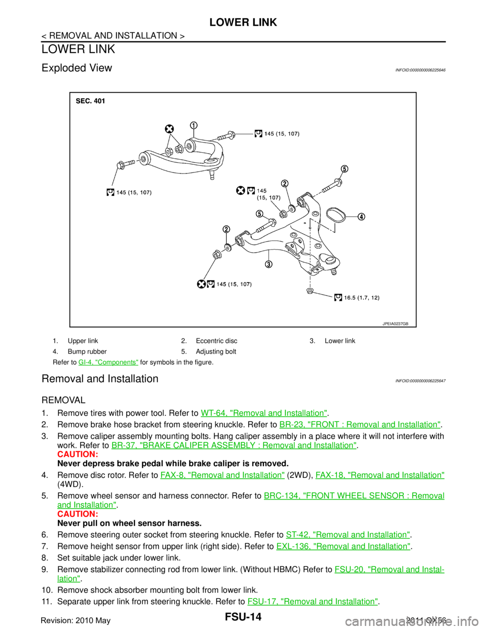
Exploded ViewINFOID:0000000006225646
Removal and InstallationINFOID:0000000006225647
REMOVAL
1. Remove tires with power tool. Refer to WT-64, "Removal and Installation".
2. Remove brake hose bracket from steering knuckle. Refer to BR-23, "
FRONT : Removal and Installation".
3. Remove caliper assembly mounting bolts. Hang caliper assembly in a place where it will not interfere with work. Refer to BR-37, "
BRAKE CALIPER ASSEMBLY : Removal and Installation".
CAUTION:
Never depress brake pedal while brake caliper is removed.
4. Remove disc rotor. Refer to FA X - 8 , "
Removal and Installation" (2WD), FAX-18, "Removal and Installation"
(4WD).
5. Remove wheel sensor and harness connector. Refer to BRC-134, "
FRONT WHEEL SENSOR : Removal
and Installation".
CAUTION:
Never pull on wheel sensor harness.
6. Remove steering outer socket fr om steering knuckle. Refer to ST-42, "
Removal and Installation".
7. Remove height sensor from upper link (right side). Refer to EXL-136, "
Removal and Installation".
8. Set suitable jack under lower link.
9. Remove stabilizer connecting rod from lower link. (Without HBMC) Refer to FSU-20, "
Removal and Instal-
lation".
10. Remove shock absorber mounting bolt from lower link.
11. Separate upper link from steering knuckle. Refer to FSU-17, "
Removal and Installation".
1. Upper link 2. Eccentric disc 3. Lower link
4. Bump rubber 5. Adjusting bolt
Refer to GI-4, "
Components" for symbols in the figure.
JPEIA0237GB
Revision: 2010 May2011 QX56
Page 2958 of 5598
FSU-16
< REMOVAL AND INSTALLATION >
LOWER LINK
2. Move tip of ball stud in axial direction to check for looseness.
If axial end play exceeds standard range, replace lower link assembly.
INSPECTION AFTER INSTALLATION
1. Check wheel sensor harness for proper connection. Refer to BRC-134, "FRONT WHEEL SENSOR :
Exploded View".
2. Check wheel alignment. Refer to FSU-7, "
Inspection".
3. Adjust neutral position of steering angle sensor. Refer to BRC-64, "
Work Procedure".
4. Adjust levelizer adjustment of height sensor. Refer to EXL-61, "
LEVELIZER ADJUSTMENT : Special
Repair Requirement".
Axial end play : Refer to
FSU-21, "
Ball Joint".
Revision: 2010 May2011 QX56
Page 2959 of 5598
UPPER LINKFSU-17
< REMOVAL AND INSTALLATION >
C
DF
G H
I
J
K L
M A
B
FSU
N
O P
UPPER LINK
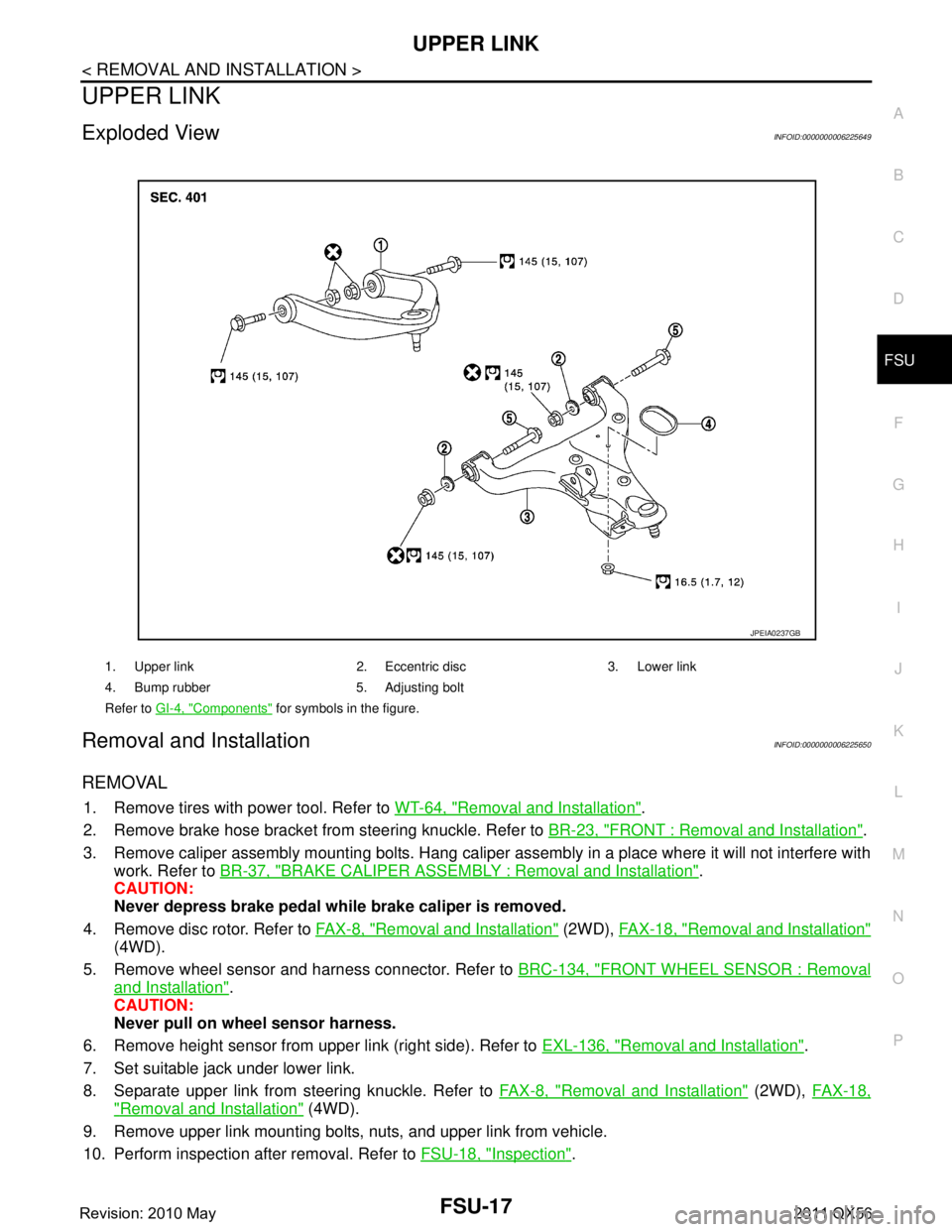
Exploded ViewINFOID:0000000006225649
Removal and InstallationINFOID:0000000006225650
REMOVAL
1. Remove tires with power tool. Refer to WT-64, "Removal and Installation".
2. Remove brake hose bracket from steering knuckle. Refer to BR-23, "
FRONT : Removal and Installation".
3. Remove caliper assembly mounting bolts. Hang caliper assembly in a place where it will not interfere with work. Refer to BR-37, "
BRAKE CALIPER ASSEMBLY : Removal and Installation".
CAUTION:
Never depress brake pedal while brake caliper is removed.
4. Remove disc rotor. Refer to FA X - 8 , "
Removal and Installation" (2WD), FAX-18, "Removal and Installation"
(4WD).
5. Remove wheel sensor and harness connector. Refer to BRC-134, "
FRONT WHEEL SENSOR : Removal
and Installation".
CAUTION:
Never pull on wheel sensor harness.
6. Remove height sensor from upper link (right side). Refer to EXL-136, "
Removal and Installation".
7. Set suitable jack under lower link.
8. Separate upper link from steering knuckle. Refer to FA X - 8 , "
Removal and Installation" (2WD), FAX-18,
"Removal and Installation" (4WD).
9. Remove upper link mounting bolts, nuts, and upper link from vehicle.
10. Perform inspection after removal. Refer to FSU-18, "
Inspection".
1. Upper link 2. Eccentric disc 3. Lower link
4. Bump rubber 5. Adjusting bolt
Refer to GI-4, "
Components" for symbols in the figure.
JPEIA0237GB
Revision: 2010 May2011 QX56
Page 2960 of 5598
FSU-18
< REMOVAL AND INSTALLATION >
UPPER LINK
INSTALLATION
Note the following, and install in the reverse order of removal.
Perform final tightening of bolts and nuts at the vehicle installation position (rubber bushing), under unladenconditions with tires on level ground.
Perform inspection after installation. Refer to FSU-18, "
Inspection".
InspectionINFOID:0000000006225651
INSPECTION AFTER REMOVAL
Appearance
Check the following items, and replace the part if necessary.
Upper link and bushing for deformation, cracks or damage.
Ball joint boot for cracks or other damage, and also for grease leakage.
Ball Joint Inspection
Manually move ball stud to confirm it moves smoothly with no binding.
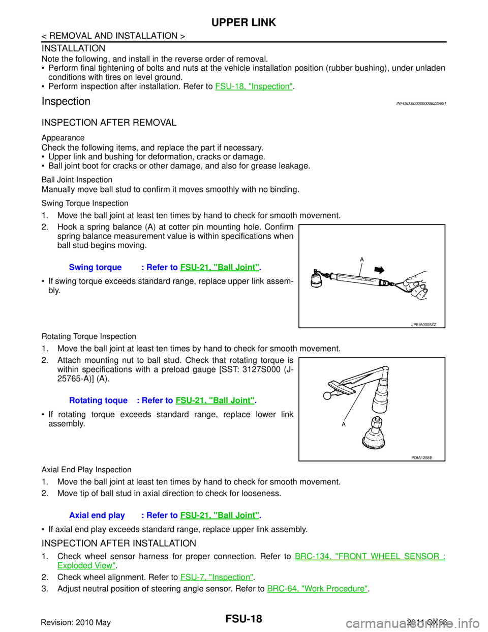
Swing Torque Inspection
1. Move the ball joint at least ten times by hand to check for smooth movement.
2. Hook a spring balance (A) at cotter pin mounting hole. Confirm
spring balance measurement value is within specifications when
ball stud begins moving.
If swing torque exceeds standard range, replace upper link assem- bly.
Rotating Torque Inspection
1. Move the ball joint at least ten times by hand to check for smooth movement.
2. Attach mounting nut to ball stud. Check that rotating torque is
within specifications with a preload gauge [SST: 3127S000 (J-
25765-A)] (A).
If rotating torque exceeds standard range, replace lower link assembly.
Axial End Play Inspection
1. Move the ball joint at least ten times by hand to check for smooth movement.
2. Move tip of ball stud in axial direction to check for looseness.
If axial end play exceeds standard range, replace upper link assembly.
INSPECTION AFTER INSTALLATION
1. Check wheel sensor harness for proper connection. Refer to BRC-134, "FRONT WHEEL SENSOR :
Exploded View".
2. Check wheel alignment. Refer to FSU-7, "
Inspection".
3. Adjust neutral position of steering angle sensor. Refer to BRC-64, "
Work Procedure".
Swing torque : Refer to
FSU-21, "
Ball Joint".
JPEIA0005ZZ
Rotating toque : Refer to FSU-21, "Ball Joint".
PDIA1258E
Axial end play : Refer to FSU-21, "Ball Joint".
Revision: 2010 May2011 QX56
Page 2963 of 5598
SERVICE DATA AND SPECIFICATIONS (SDS)
FSU-21
< SERVICE DATA AND SPECIFICATIONS (SDS)
C
D F
G H
I
J
K L
M A
B
FSU
N
O P
SERVICE DATA AND SPECIFICATIONS (SDS)
SERVICE DATA AND SPECIFICATIONS (SDS)
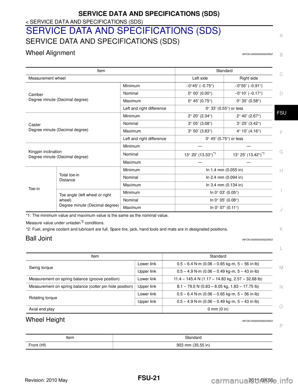
Wheel AlignmentINFOID:0000000006225652
*1: The minimum value and maximum value is the same as the nominal value.
Measure value under unladen
*2 conditions.
*2: Fuel, engine coolant and lubricant are full. Spare tire, jack, hand tools and mats are in designated positions.
Ball JointINFOID:0000000006225653
Wheel HeightINFOID:0000000006225654
Item Standard
Measurement wheel Left side Right side
Camber
Degree minute (Decimal degree) Minimum
−0 °45 ′ ( −0.75 °) −0°55 ′ ( −0.91 °)
Nominal 0 ° 00 ′ (0.00 °) −0°10 ′ ( −0.17 °)
Maximum 0 ° 45 ′ (0.75 °)0 ° 35 ′ (0.58 °)
Left and right difference 0 ° 33 ′ (0.55 °) or less
Caster
Degree minute (Decimal degree) Minimum 2
° 20 ′ (2.34 °)2 ° 40 ′ (2.67 °)
Nominal 3 ° 05 ′ (3.08 °)3 ° 25 ′ (3.42 °)
Maximum 3 ° 50 ′ (3.83 °)4 ° 10 ′ (4.16
° )
Left and right difference 0 ° 45 ′ (0.75 °) or less
Kingpin inclination
Degree minute (Decimal degree) Minimum — —
Nominal
13° 20 ′ (13.33 °)
*113 ° 25 ′ (13.42 °)*1
Maximum — —
To e - i n To t a l t o e - i n
Distance
Minimum In 1.4 mm (0.055 in)
Nominal In 2.4 mm (0.094 in)
Maximum In 3.4 mm (0.134 in)
Toe angle (left wheel or right
wheel)
Degree minute (Decimal degree) Minimum In 0
° 03 ′ (0.05 °)
Nominal In 0 ° 05 ′ (0.08 °)
Maximum In 0 ° 07 ′ (0.11 °)
Item Standard
Swing torque Lower link 0.5 – 6.4 N·m (0.06 – 0.65 kg-m, 5 – 56 in-lb)
Upper link 0.5 – 4.9 N·m (0.06 – 0.49 kg-m, 5 – 43 in-lb)
Measurement on spring balance (groove position) Lower link 11.4 – 145.4 N (1.17 – 14.83 kg, 2.57 – 32.68 lb)
Measurement on spring balance (cotter pin hole position) Upper link 8.1 – 79.0 N (0.83 – 8.05 kg, 1.83 – 17.75 lb)
Rotating torque Lower link 0.5 – 6.4 N·m (0.06 – 0.65 kg-m, 5 – 56 in-lb)
Upper link 0.5 – 4.9 N·m (0.06 – 0.49 kg-m, 5 – 43 in-lb)
Axial end play 0 mm (0 in)
Item Standard
Front (Hf) 903 mm (35.55 in)
Revision: 2010 May2011 QX56
Page 2965 of 5598
GI-1
GENERAL INFORMATION
C
DE
F
G H
I
J
K L
M B
GI
SECTION GI
N
O P
CONTENTS
GENERAL INFORMATION
HOW TO USE THIS MANU AL ......................3
HOW TO USE THIS MANUAL ....................... .....3
Description .......................................................... ......3
Terms ........................................................................3
Units ..........................................................................3
Contents ....................................................................3
Relation between Illustrations and Descriptions .......4
Components ..............................................................4
HOW TO FOLLOW TROUBLE DIAGNOSES .....6
Description ................................................................6
How to Follow Test Groups in Trouble Diagnosis ......6
Key to Symbols Signifying Measurements or Pro-
cedures ............................................................... ......
7
HOW TO READ WIRING DIAGRAMS ................9
Connector Symbols ............................................. ......9
Sample/Wiring Diagram -Example- .........................10
Connector Information .............................................12
ABBREVIATIONS .......................................... ....14
Abbreviation List .................................................. ....14
TIGHTENING TORQUE OF STANDARD
BOLTS ................................................................
19
Description .......................................................... ....19
Tightening Torque Table (New Standard Includ-
ed) ...........................................................................
19
RECOMMENDED CHEMICAL PRODUCTS
AND SEALANTS ................................................
22
Recommended Chemical Products and Sealants ....22
VEHICLE INFORMATION ............................23
IDENTIFICATION INFORMATION ................. ....23
Model Variation ................................................... ....23
Information About Identification or Model Code ......23
Dimensions .............................................................25
Wheels & Tires ........................................................25
PRECAUTION ..............................................26
PRECAUTIONS .................................................26
Description ........................................................... ....26
Precaution for Supplemental Restraint System
(SRS) "AIR BAG" and "SEAT BELT PRE-TEN-
SIONER" .................................................................
26
Precautions For Xenon Headlamp Service .............26
Precaution Necessary for Steering Wheel Rota-
tion after Battery Disconnect ...................................
27
Precaution for Procedure without Cowl Top Cover ....27
General Precautions ................................................27
Three Way Catalyst .................................................29
Multiport Fuel Injection System or Engine Control
System .....................................................................
29
Hoses ......................................................................29
Engine Oils ..............................................................30
Air Conditioning .......................................................31
Fuel ..........................................................................31
LIFTING POINT .................................................32
Pantograph Jack ......................................................32
Garage Jack and Safety Stand ................................32
2-Pole Lift ................................................................33
TOW TRUCK TOWING .....................................34
Tow Truck Towing ...................................................34
Vehicle Recovery (Freeing a Stuck Vehicle) ...........34
BASIC INSPECTION ...................................36
SERVICE INFORMATION FOR ELECTRICAL
INCIDENT ..........................................................
36
Work Flow ............................................................ ....36
Control Units and Electrical Parts ............................36
How to Check Terminal ...........................................37
Intermittent Incident .................................................40
Circuit Inspection .....................................................43
CONSULT-III/GST CHECKING SYSTEM .........48
Description ...............................................................48
CONSULT-III Function and System Application*1 ....48
Revision: 2010 May2011 QX56
Page 2978 of 5598

GI-14
< HOW TO USE THIS MANUAL >
ABBREVIATIONS
ABBREVIATIONS
Abbreviation ListINFOID:0000000006280882
The following ABBREVIATIONS are used:
A
B
C
D
ABBREVIATION DESCRIPTION
A/C Air conditioner
A/C Air conditioning
A/F sensor Air fuel ratio sensor A/T Automatic transaxle/transmission
ABS Anti-lock braking system
ACCS Advance climate control system ACL Air cleaner
AP Accelerator pedal
APP Accelerator pedal position ATF Automatic transmission fluid AV Audio visual
AWD All wheel drive
ABBREVIATION DESCRIPTION BARO Barometric pressureBCM Body control module
BLSD Brake limited slip differential BPP Brake pedal positionBSI Blind spot intervention
BSW Blind spot warning
ABBREVIATION DESCRIPTION CKP Crankshaft positionCL Closed loop
CMP Camshaft position CPP Clutch pedal positionCTP Closed throttle position
CVT Continuously Variable transaxle/transmission
ABBREVIATION DESCRIPTION D
1Drive range first gear
D
2Drive range second gear
D
3Drive range third gear
D
4Drive range fourth gear
DCA Distance control assist DFI Direct fuel injection system
DLC Data link connector
DTC Diagnostic trouble code
Revision: 2010 May2011 QX56
Page 2982 of 5598

GI-18
< HOW TO USE THIS MANUAL >
ABBREVIATIONS
2
3
4
5
6
7
121st range second gear
1GR First gear
ABBREVIATION DESCRIPTION 2
12nd range first gear
2
22nd range second gear
2GR Second gear
2WD 2-Wheel Drive
ABBREVIATION DESCRIPTION 3GR Third gear
ABBREVIATION DESCRIPTION 4GR Fourth gear
4WAS Four wheel active steer 4WD Four wheel drive
ABBREVIATION DESCRIPTION 5GR Fifth gear
ABBREVIATION DESCRIPTION 6GR Sixth gear
ABBREVIATION DESCRIPTION 7GR Seventh gear
ABBREVIATION DESCRIPTION
Revision: 2010 May2011 QX56