Page 1780 of 5598
DLK-244
< REMOVAL AND INSTALLATION >
REAR DOOR LOCK
INSIDE HANDLE : Removal and Installation
INFOID:0000000006226103
REMOVAL
1. Remove rear door finisher. Refer to INT-16, "Removal and Installation".
2. Remove inside handle escutcheon. Refer to INT-16, "
Exploded View"
3. Remove inside handle mounting screws, and then remove inside handle.
INSTALLATION
Note the following items, and then install in the reverse order of removal.
CAUTION:
Check door lock cables are properly engaged with inside handle.
After installation, check door open/close, lock/unlock operation.
OUTSIDE HANDLE
OUTSIDE HANDLE : Removal and InstallationINFOID:0000000006226104
REMOVAL
1. Fully close rear door glass.
2. Remove rear door finisher. Refer to INT-16, "
Removal and Installation".
3. Remove sealing screen. NOTE:
Cat the buty-tape so that some parts of the buty-t ape do not remain on the sealing screen, if the sealing
screen is reused.
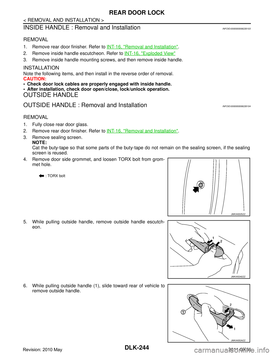
4. Remove door side grommet, and loosen TORX bolt from grom- met hole.
5. While pulling outside handle, remove outside handle escutch- eon.
6. While pulling outside handle (1), slide toward rear of vehicle to remove outside handle.
: TORX bolt
JMKIA0025ZZ
JMKIA5342ZZ
JMKIA0524ZZ
Revision: 2010 May2011 QX56
Page 1781 of 5598
REAR DOOR LOCKDLK-245
< REMOVAL AND INSTALLATION >
C
DE
F
G H
I
J
L
M A
B
DLK
N
O P
7. Remove front gasket and rear gasket.
8. Slide toward rear of vehicle to remove outside handle bracket.
9. Disconnect door lock cable from outside handle bracket.
INSTALLATION
Note the following items, and then install in the reverse order of removal.
CAUTION:
Check door lock cable is properly engaged with outside handle bracket.
After installation, check door op en/close, lock/unlock operation.
JMKIA2652ZZ
Revision: 2010 May2011 QX56
Page 1782 of 5598
DLK-246
< REMOVAL AND INSTALLATION >
BACK DOOR LOCK
BACK DOOR LOCK
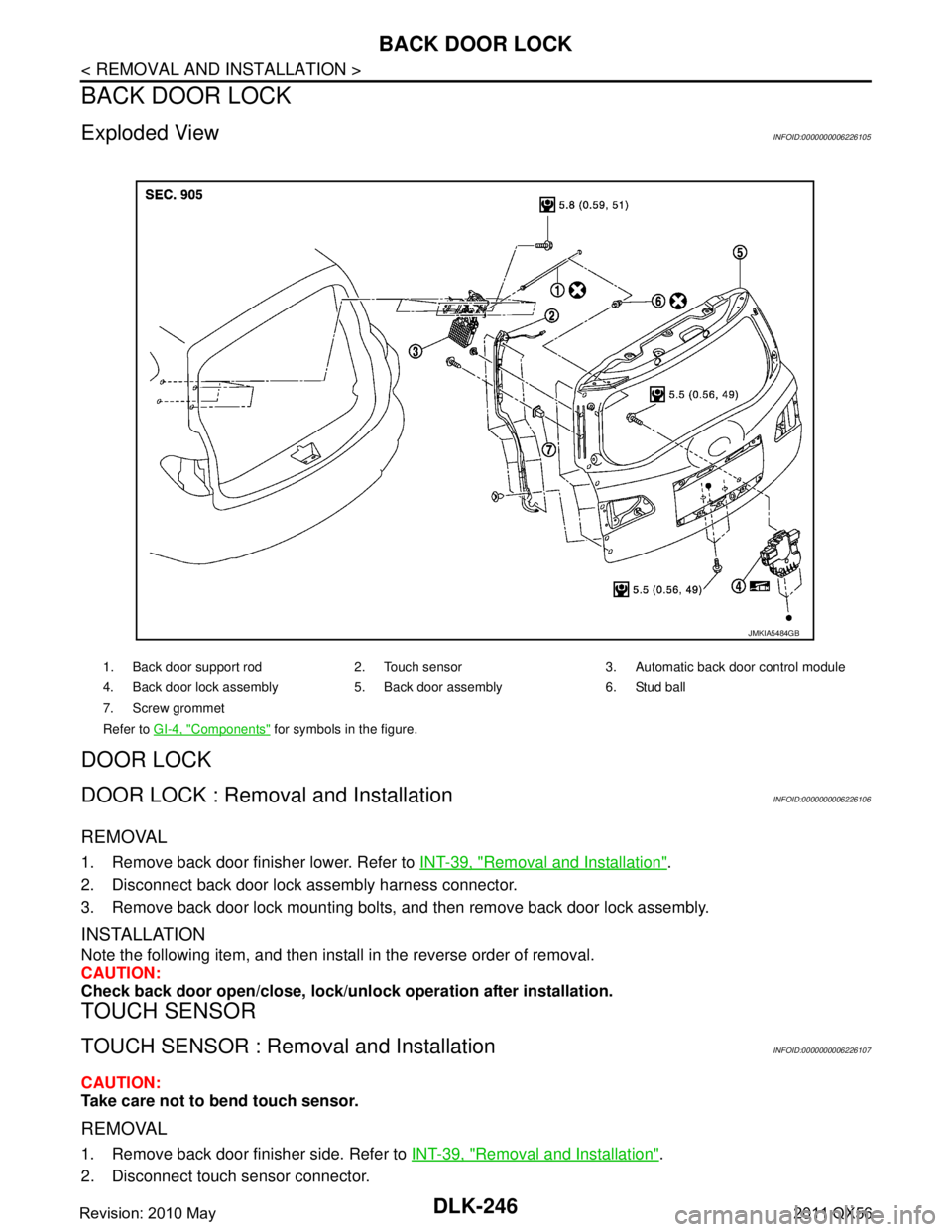
Exploded ViewINFOID:0000000006226105
DOOR LOCK
DOOR LOCK : Removal and InstallationINFOID:0000000006226106
REMOVAL
1. Remove back door finisher lower. Refer to INT-39, "Removal and Installation".
2. Disconnect back door lock assembly harness connector.
3. Remove back door lock mounting bolts, and then remove back door lock assembly.
INSTALLATION
Note the following item, and then install in the reverse order of removal.
CAUTION:
Check back door open/close, lock/unlo ck operation after installation.
TOUCH SENSOR
TOUCH SENSOR : Removal and InstallationINFOID:0000000006226107
CAUTION:
Take care not to bend touch sensor.
REMOVAL
1. Remove back door finisher side. Refer to INT-39, "Removal and Installation".
2. Disconnect touch sensor connector.
1. Back door support rod 2. Touch sensor 3. Automatic back door control module
4. Back door lock assembly 5. Back door assembly 6. Stud ball
7. Screw grommet
Refer to GI-4, "
Components" for symbols in the figure.
JMKIA5484GB
Revision: 2010 May2011 QX56
Page 1783 of 5598
BACK DOOR LOCKDLK-247
< REMOVAL AND INSTALLATION >
C
DE
F
G H
I
J
L
M A
B
DLK
N
O P
3. Remove clips and TORX screws of touch sensor.
4. Pull harness of touch sensor out of back door and remove touch sensor.
INSTALLATION
Note the following item, and then install in the reverse order of removal.
CAUTION:
Check back door open/close operation after installation.
BACK DOOR SUPPORT ROD
BACK DOOR SUPPORT ROD : Removal and InstallationINFOID:0000000006226108
REMOVAL
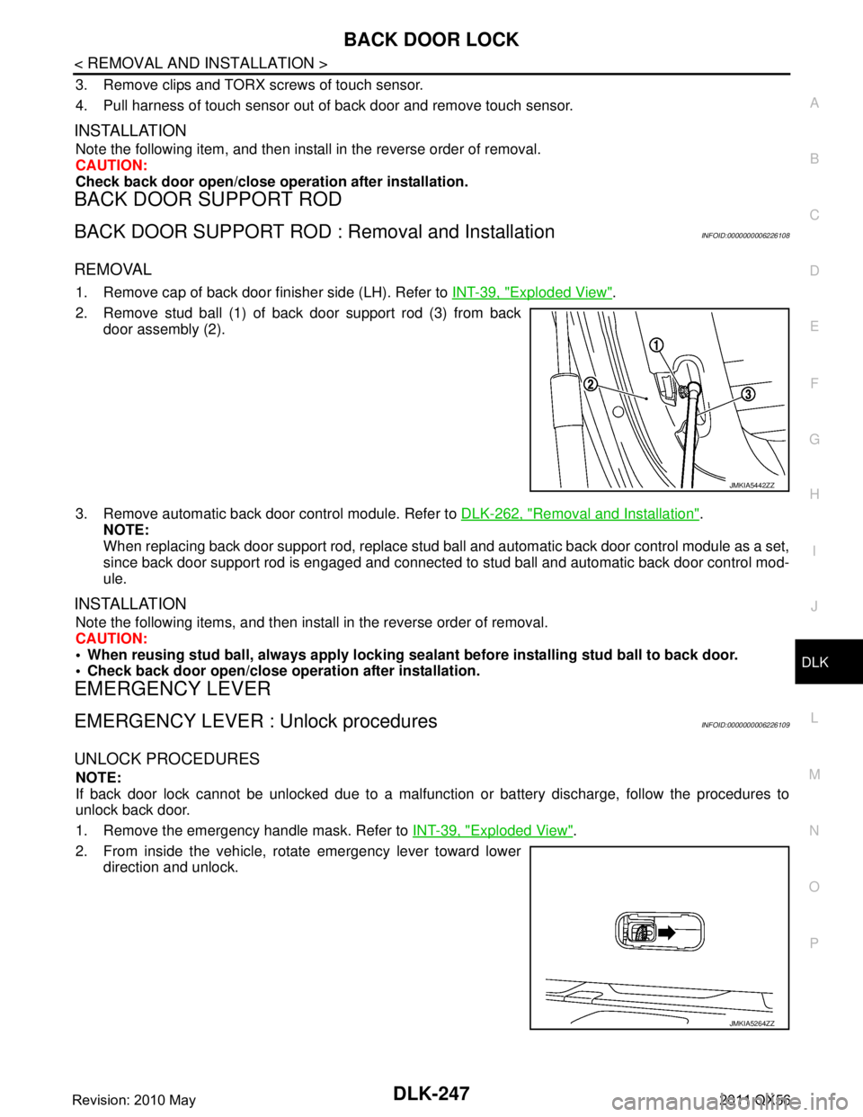
1. Remove cap of back door finisher side (LH). Refer to INT-39, "Exploded View".
2. Remove stud ball (1) of back door support rod (3) from back door assembly (2).
3. Remove automatic back door control module. Refer to DLK-262, "
Removal and Installation".
NOTE:
When replacing back door support rod, replace stud ba ll and automatic back door control module as a set,
since back door support rod is engaged and connected to stud ball and automatic back door control mod-
ule.
INSTALLATION
Note the following items, and then install in the reverse order of removal.
CAUTION:
When reusing stud ball, always a pply locking sealant before installing stud ball to back door.
Check back door open/close opera tion after installation.
EMERGENCY LEVER
EMERGENCY LEVER : Unlock proceduresINFOID:0000000006226109
UNLOCK PROCEDURES
NOTE:
If back door lock cannot be unlocked due to a malfuncti on or battery discharge, follow the procedures to
unlock back door.
1. Remove the emergency handle mask. Refer to INT-39, "
Exploded View".
2. From inside the vehicle, rotate emergency lever toward lower direction and unlock.
JMKIA5442ZZ
JMKIA5264ZZ
Revision: 2010 May2011 QX56
Page 1784 of 5598
DLK-248
< REMOVAL AND INSTALLATION >
FUEL FILLER LID OPENER
FUEL FILLER LID OPENER
Exploded ViewINFOID:0000000006226110
Removal and InstallationINFOID:0000000006226111
NOTE:
When fuel filler lid lock actuator (1) is a defective operation, pull the
rod to open fuel filler lid.
REMOVAL
1. Fuel filler spring 2. TORX bolt 3. Fuel filler lid assembly
4. Fuel lid bumper rubber 5. Lock nut 6. Lock & rod assembly
7. Fuel filler lid lock actuator: Pawl
: Vehicle front
JMKIA5269ZZ
JMKIA1960ZZ
Revision: 2010 May2011 QX56
Page 1785 of 5598
FUEL FILLER LID OPENERDLK-249
< REMOVAL AND INSTALLATION >
C
DE
F
G H
I
J
L
M A
B
DLK
N
O P
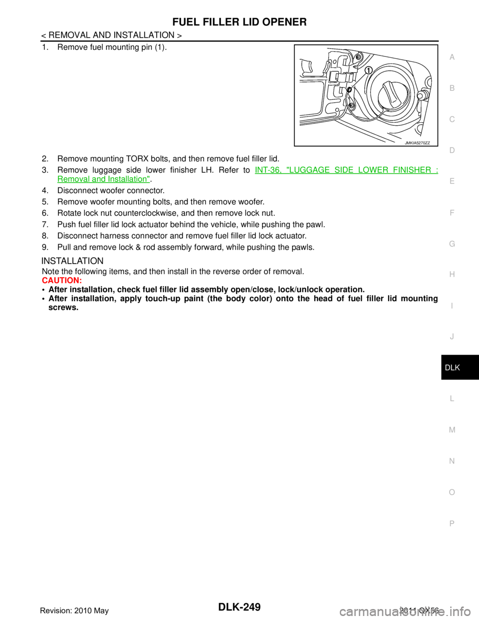
1. Remove fuel mounting pin (1).
2. Remove mounting TORX bolts, and then remove fuel filler lid.
3. Remove luggage side lower finisher LH. Refer to INT-36, "
LUGGAGE SIDE LOWER FINISHER :
Removal and Installation".
4. Disconnect woofer connector.
5. Remove woofer mounting bolts, and then remove woofer.
6. Rotate lock nut counterclockwise, and then remove lock nut.
7. Push fuel filler lid lock actuator behind the vehicle, while pushing the pawl.
8. Disconnect harness connector and remove fuel filler lid lock actuator.
9. Pull and remove lock & rod assembly forward, while pushing the pawls.
INSTALLATION
Note the following items, and then install in the reverse order of removal.
CAUTION:
After installation, check fuel filler li d assembly open/close, lock/unlock operation.
After installation, apply touch-up paint (the body color) onto the head of fuel filler lid mounting
screws.
JMKIA5270ZZ
Revision: 2010 May2011 QX56
Page 1786 of 5598
DLK-250
< REMOVAL AND INSTALLATION >
KEY CYLINDER
KEY CYLINDER
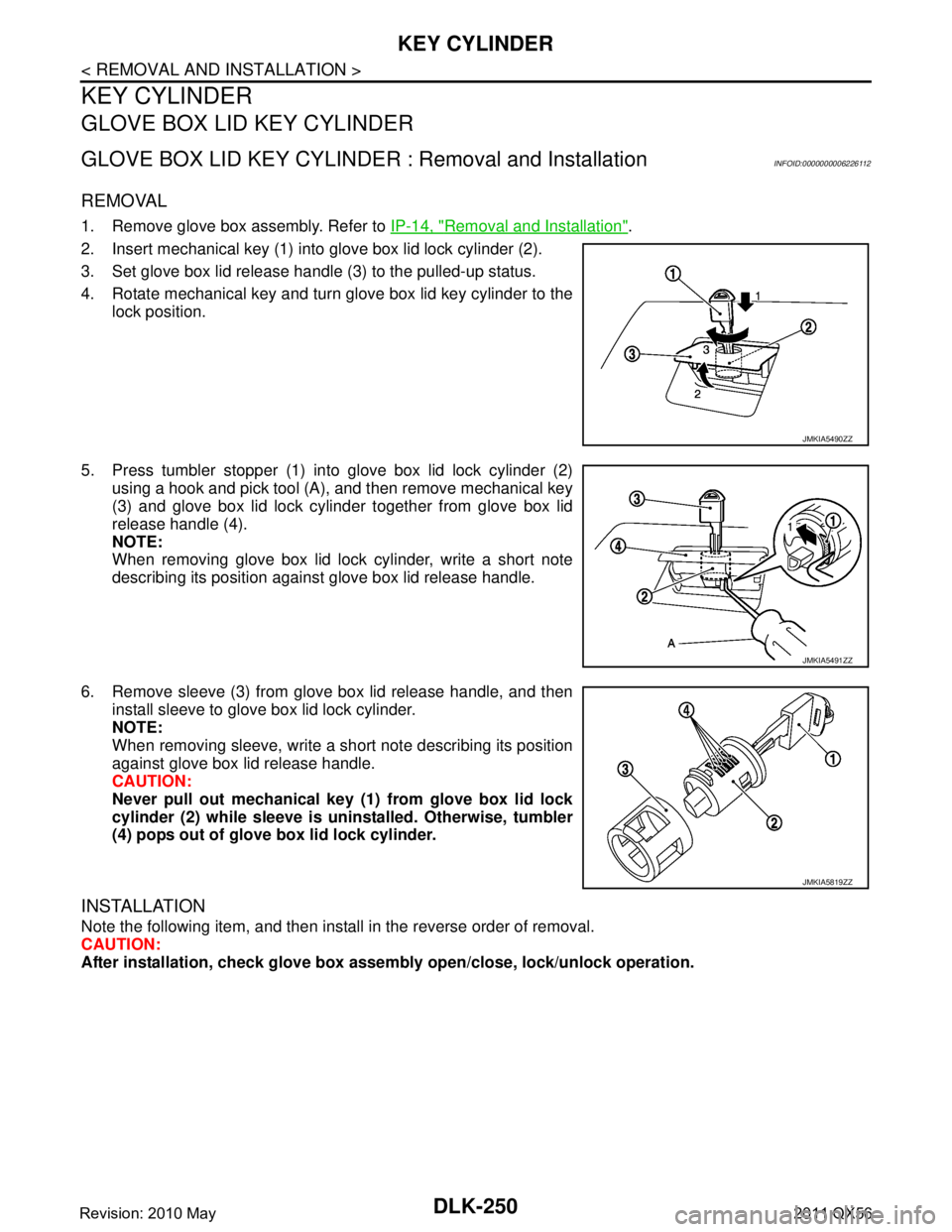
GLOVE BOX LID KEY CYLINDER
GLOVE BOX LID KEY CYLINDER : Removal and InstallationINFOID:0000000006226112
REMOVAL
1. Remove glove box assembly. Refer to IP-14, "Removal and Installation".
2. Insert mechanical key (1) into glove box lid lock cylinder (2).
3. Set glove box lid release handle (3) to the pulled-up status.
4. Rotate mechanical key and turn glove box lid key cylinder to the lock position.
5. Press tumbler stopper (1) into glove box lid lock cylinder (2) using a hook and pick tool (A), and then remove mechanical key
(3) and glove box lid lock cylinder together from glove box lid
release handle (4).
NOTE:
When removing glove box lid lock cylinder, write a short note
describing its position against glove box lid release handle.
6. Remove sleeve (3) from glove box lid release handle, and then install sleeve to glove box lid lock cylinder.
NOTE:
When removing sleeve, write a short note describing its position
against glove box lid release handle.
CAUTION:
Never pull out mechanical key (1) from glove box lid lock
cylinder (2) while sl eeve is uninstalled. Otherwise, tumbler
(4) pops out of glove box lid lock cylinder.
INSTALLATION
Note the following item, and then install in the reverse order of removal.
CAUTION:
After installation, check glove box assem bly open/close, lock/unlock operation.
JMKIA5490ZZ
JMKIA5491ZZ
JMKIA5819ZZ
Revision: 2010 May2011 QX56
Page 1796 of 5598
DLK-260
< REMOVAL AND INSTALLATION >
INTELLIGENT KEY BATTERY
INTELLIGENT KEY BATTERY
Removal and InstallationINFOID:0000000006226127
1. Release the lock knob at the back of the Intelligent Key and remove the mechanical key.
2. Insert a flat-blade screwdriver (A) wrapped with a cloth into the slit of the corner and twist it to separate the upper part from the
lower part.
CAUTION:
Do not touch the circuit board or battery terminal.
The key fob is water-resistant. However, if it does get wet,immediately wipe it dry.
3. Replace the battery with new one.
4. Align the tips of the upper and lower parts, and then push them together until it is securely closed.
CAUTION:
When replacing battery, keep dirt, grease, and other for-
eign materials off the electrode contact area.
After replacing the battery, check that all Intelligent Key
functions work normally.
PIIB6221E
Battery replacement :Coin-type lithium battery
(CR2025)
PIIB6222E
Revision: 2010 May2011 QX56