2011 INFINITI QX56 lock
[x] Cancel search: lockPage 1748 of 5598
DLK-212
< SYMPTOM DIAGNOSIS >
SQUEAK AND RATTLE TROUBLE DIAGNOSES
Most of these incidents can be repaired by adjusting, securing or insulating the item(s) or component(s) caus-
ing the noise.
SUNROOF/HEADLINING
Noises in the sunroof/headlining area c an often be traced to one of the following:
1. Sunroof lid, rail, linkage or seals making a rattle or light knocking noise
2. Sunvisor shaft shaking in the holder
3. Front or rear windshield touching headlining and squeaking
Again, pressing on the components to stop the noise while duplicating the conditions can isolate most of these
incidents. Repairs usually consist of insulating with felt cloth tape.
SEATS
When isolating seat noise it is important to note t he position the seat is in and the load placed on the seat
when the noise is present. These conditions should be duplicated when verifying and isolating the cause of
the noise.
Cause of seat noise include:
1. Headrest rods and holder
2. A squeak between the seat pad cushion and frame
3. Rear seatback lock and bracket
These noises can be isolated by moving or pressing on the suspected components while duplicating the con-
ditions under which the noise occurs. Most of thes e incidents can be repaired by repositioning the component
or applying urethane tape to the contact area.
UNDERHOOD
Some interior noise may be caused by components under the hood or on the engine wall. The noise is then
transmitted into the passenger compartment.
Causes of transmitted underhood noise include:
1. Any component mounted to the engine wall
2. Components that pass through the engine wall
3. Engine wall mounts and connectors
4. Loose radiator mounting pins
5. Hood bumpers out of adjustment
6. Hood striker out of adjustment
These noises can be difficult to isolate since they cannot be reached from the interior of the vehicle. The best
method is to secure, move or insulate one component at a time and test drive the \
vehicle. Also, engine RPM
or load can be changed to isolate the noise. Repairs can usually be made by moving, adjusting, securing, or
insulating the component causing the noise.
Revision: 2010 May2011 QX56
Page 1753 of 5598
HOOD
DLK-217
< REMOVAL AND INSTALLATION >
C
D E
F
G H
I
J
L
M A
B
DLK
N
O P
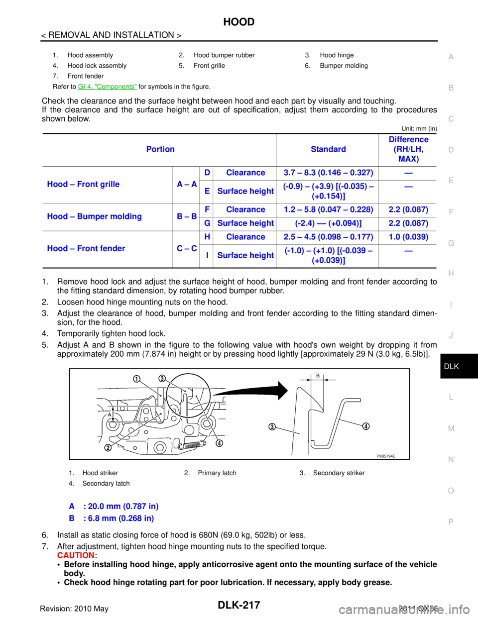
Check the clearance and the surface height betw een hood and each part by visually and touching.
If the clearance and the surface height are out of spec ification, adjust them according to the procedures
shown below.
Unit: mm (in)
1. Remove hood lock and adjust the surface height of hood, bumper molding and front fender according to
the fitting standard dimension, by rotating hood bumper rubber.
2. Loosen hood hinge mounting nuts on the hood.
3. Adjust the clearance of hood, bumper molding and fr ont fender according to the fitting standard dimen-
sion, for the hood.
4. Temporarily tighten hood lock.
5. Adjust A and B shown in the figure to the following value with hood's own weight by dropping it from approximately 200 mm (7.874 in) height or by pressi ng hood lightly [approximately 29 N (3.0 kg, 6.5lb)].
6. Install as static closing force of hood is 680N (69.0 kg, 502lb) or less.
7. After adjustment, tighten hood hinge mounting nuts to the specified torque. CAUTION:
Before installing hood hinge, apply anticorrosive agent onto th e mounting surface of the vehicle
body.
Check hood hinge rotating pa rt for poor lubrication. If necessary, apply body grease.
1. Hood assembly 2. Hood bumper rubber 3. Hood hinge
4. Hood lock assembly 5. Front grille 6. Bumper molding
7. Front fender
Refer to GI-4, "
Components" for symbols in the figure.
Portion Standard Difference
(RH/LH, MAX)
Hood – Front grille A – A D Clearance 3.7 – 8.3 (0.146 – 0.327) —
E Surface height (-0.9) – (+3.9) [(-0.035) –
(+0.154)] —
Hood – Bumper molding B – B F Clearance 1.2 – 5.8 (0.047 – 0.228) 2.2 (0.087)
G Surface height (-2.4) –– (+0.094)] 2.2 (0.087)
Hood – Front fender C – C H Clearance 2.5 – 4.5 (0.098 – 0.177) 1.0 (0.039)
I Surface height (-1.0) – (+1.0) [(-0.039 –
(+0.039)] —
1. Hood striker 2. Primary latch 3. Secondary striker
4. Secondary latch
A : 20.0 mm (0.787 in)
B : 6.8 mm (0.268 in)
PIIB5794E
Revision: 2010 May2011 QX56
Page 1757 of 5598
RADIATOR CORE SUPPORTDLK-221
< REMOVAL AND INSTALLATION >
C
DE
F
G H
I
J
L
M A
B
DLK
N
O P
6. Disconnect all harness clips.
7. Remove hood lock assembly. Refer to DLK-238, "
Removal and Installation".
8. Remove fixing clips of air guide seal.
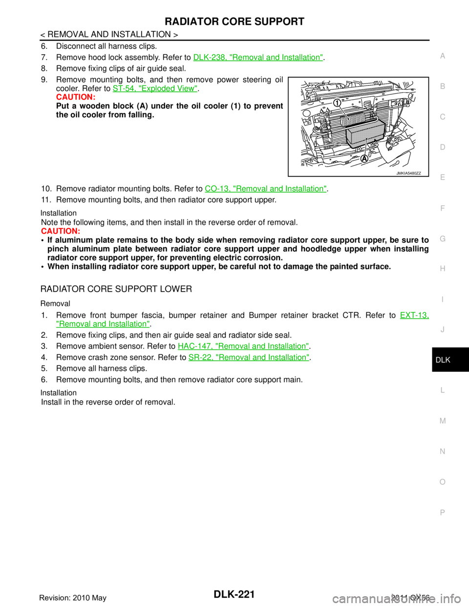
9. Remove mounting bolts, and then remove power steering oil cooler. Refer to ST-54, "
Exploded View".
CAUTION:
Put a wooden block (A) under the oil cooler (1) to prevent
the oil cooler from falling.
10. Remove radiator mounting bolts. Refer to CO-13, "
Removal and Installation".
11. Remove mounting bolts, and then radiator core support upper.
Installation
Note the following items, and then install in the reverse order of removal.
CAUTION:
If aluminum plate remains to the body side when removing radiator core support upper, be sure to
pinch aluminum plate between radiator core support upper and hoodledge upper when installing
radiator core support upper, for preventing electric corrosion.
When installing radiator core support upper, be careful not to damage the painted surface.
RADIATOR CORE SUPPORT LOWER
Removal
1. Remove front bumper fascia, bumper retainer and Bumper retainer bracket CTR. Refer to EXT-13,
"Removal and Installation".
2. Remove fixing clips, and then air guide seal and radiator side seal.
3. Remove ambient sensor. Refer to HAC-147, "
Removal and Installation".
4. Remove crash zone sensor. Refer to SR-22, "
Removal and Installation".
5. Remove all harness clips.
6. Remove mounting bolts, and then remove radiator core support main.
Installation
Install in the reverse order of removal.
JMKIA5480ZZ
Revision: 2010 May2011 QX56
Page 1760 of 5598
DLK-224
< REMOVAL AND INSTALLATION >
FRONT DOOR
FRONT DOOR
Exploded ViewINFOID:0000000006226074
DOOR ASSEMBLY
DOOR ASSEMBLY : Removal and InstallationINFOID:0000000006226075
CAUTION:
Perform work with 2 workers, because of its heavy weight.
When removing and installing front door assembly, support door with a jack and shop cloth to pro-
tect door and body.
REMOVAL
1. Remove mounting bolt of door check link on the vehicle.
2. Disconnect front door harness connector.
3. Remove door hinge mounting nuts (door side), and then remove door assembly.
INSTALLATION
Note the following items, and then install in the reverse order of removal.
CAUTION:
Apply anticorrosive agent onto the mounting surface.
Check front door open/close, lock/un lock operation after installation.
Check door hinge rotating pa rt for poor lubrication. If necessary, apply body grease.
After installation, perform th e fitting adjustment. Refer to DLK-225, "
DOOR ASSEMBLY : Adjust-
ment".
After installation, apply touch-up paint (the body color) onto the head of door hinge mounting nuts.
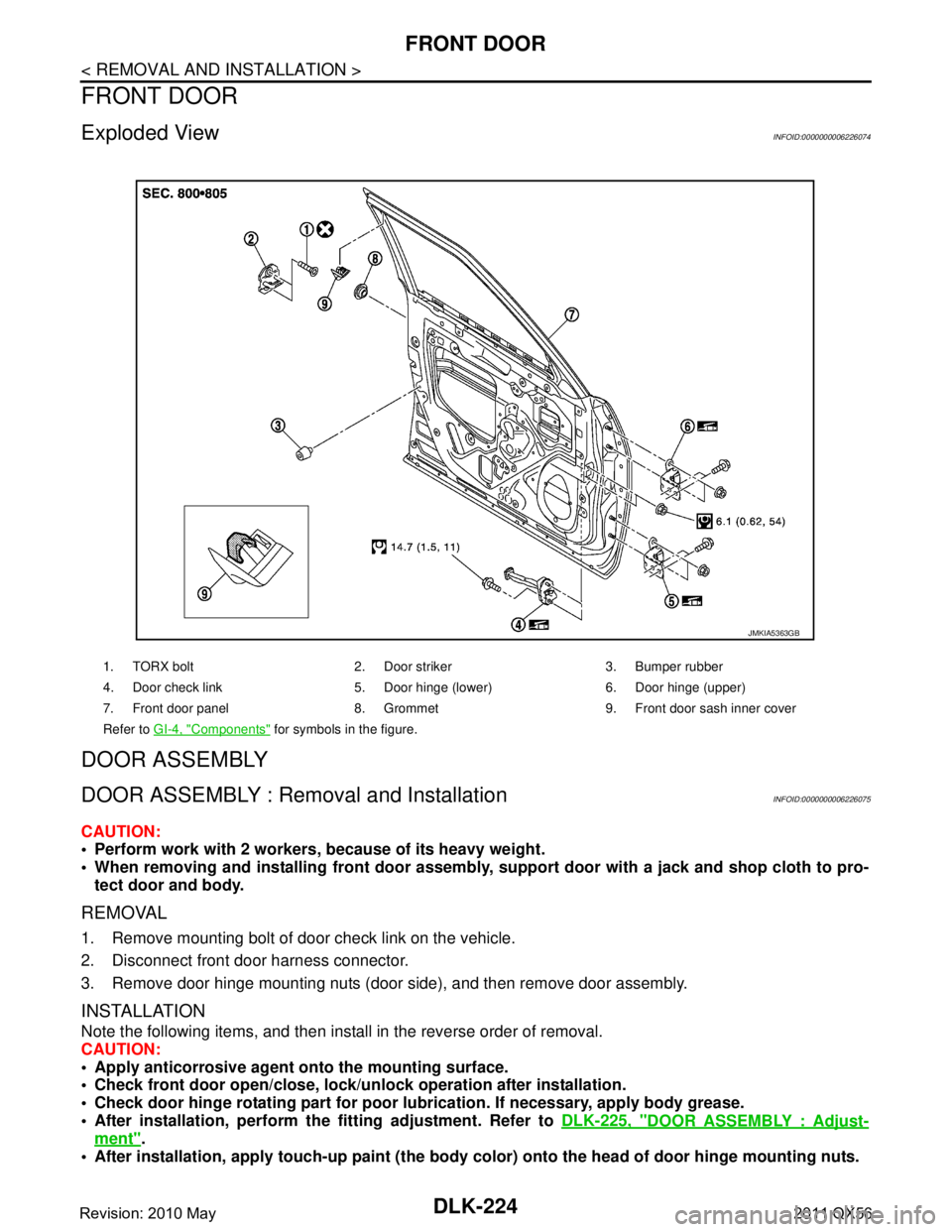
1. TORX bolt 2. Door striker 3. Bumper rubber
4. Door check link 5. Door hinge (lower) 6. Door hinge (upper)
7. Front door panel 8. Grommet 9. Front door sash inner cover
Refer to GI-4, "
Components" for symbols in the figure.
JMKIA5363GB
Revision: 2010 May2011 QX56
Page 1762 of 5598
DLK-226
< REMOVAL AND INSTALLATION >
FRONT DOOR
4. Temporarily tighten door hinge mounting nuts on door side.
5. Loosen door hinge mounting bolts on body side.
6. Raise front door at rear end to adjust clearance of the front door according to the fitting standard dimen-
sion.
7. After adjustment tighten bolts and nuts to the specified torque. CAUTION:
After installation, apply touch-up paint (the bo dy color) onto the head of hinge mounting bolts
and nuts.
Check door hinge rotating part for poor lubrication. If necessary, apply body grease.
8. Install front fender. Refer to refer to DLK-222, "
FRONT FENDER : Removal and Installation".
DOOR STRIKER ADJUSTMENT
Adjust door striker so that it becomes parallel with door lock insertion direction.
DOOR STRIKER
DOOR STRIKER : Removal and InstallationINFOID:0000000006226077
REMOVAL
Remove TORX bolts, and then remove door striker.
INSTALLATION
Note the following items, and then install in the reverse order of removal.
CAUTION:
Check front door open/close, operation after installation.
After installation, be sure to perf orm the fitting adjustment. Refer to DLK-225, "
DOOR ASSEMBLY :
Adjustment".
DOOR HINGE
DOOR HINGE : Removal and InstallationINFOID:0000000006226078
REMOVAL
CAUTION:
Perform work with 2 workers, because of its heavy weight.
When removing and installing front door assembly, support door with a jack and shop cloth to pro-
tect door and body.
1. Remove front fender. Refer to DLK-222, "
FRONT FENDER : Removal and Installation".
2. Remove front door assembly. Refer to DLK-224, "
DOOR ASSEMBLY : Removal and Installation".
3. Remove front door hinge mounting bolts (body side), and then remove front door hinge.
INSTALLATION
Note the following items, and then install in the reverse order of removal.
CAUTION:
Apply anticorrosive agent onto the mounting surface.
Check front door open/close, lock/un lock operation after installation.
Check door hinge rotating pa rt for poor lubrication. If necessary, apply body grease.
After installation, perform th e fitting adjustment. Refer to DLK-225, "
DOOR ASSEMBLY : Adjust-
ment".
After installation, apply touch-up paint (the body color) onto the head of door hinge mounting nuts.
DOOR CHECK LINK
DOOR CHECK LINK : Re moval and InstallationINFOID:0000000006226079
REMOVAL
1. Fully close the front door window.
2. Remove front door finisher. Refer to INT-14, "
Removal and Installation".
3. Remove front door speaker mounting bolts.
4. Disconnect connector and remove front door speaker.
Revision: 2010 May2011 QX56
Page 1764 of 5598
DLK-228
< REMOVAL AND INSTALLATION >
REAR DOOR
REAR DOOR
Exploded ViewINFOID:0000000006226080
DOOR ASSEMBLY
DOOR ASSEMBLY : Removal and InstallationINFOID:0000000006226081
CAUTION:
Perform work with 2 workers, because of it’s heavy weight.
When removing and installing rear door assembly, support door with a jack and shop cloth to pro-
tect door and body.
REMOVAL
1. Remove rear door harness grommet, and then pull out door harness from the vehicle.
2. Disconnect rear door harness connector.
3. Remove mounting bolt of door check link on the vehicle.
4. Remove door hinge mounting nuts (door side), and then remove rear door assembly.
INSTALLATION
Note the following items, and then install in the reverse order of removal.
CAUTION:
Apply anticorrosive agent onto the mounting surface.
Check rear door open/close, lock/unl ock operation after installation.
Check door hinge rotating pa rt for poor lubrication. If necessary, apply body grease.
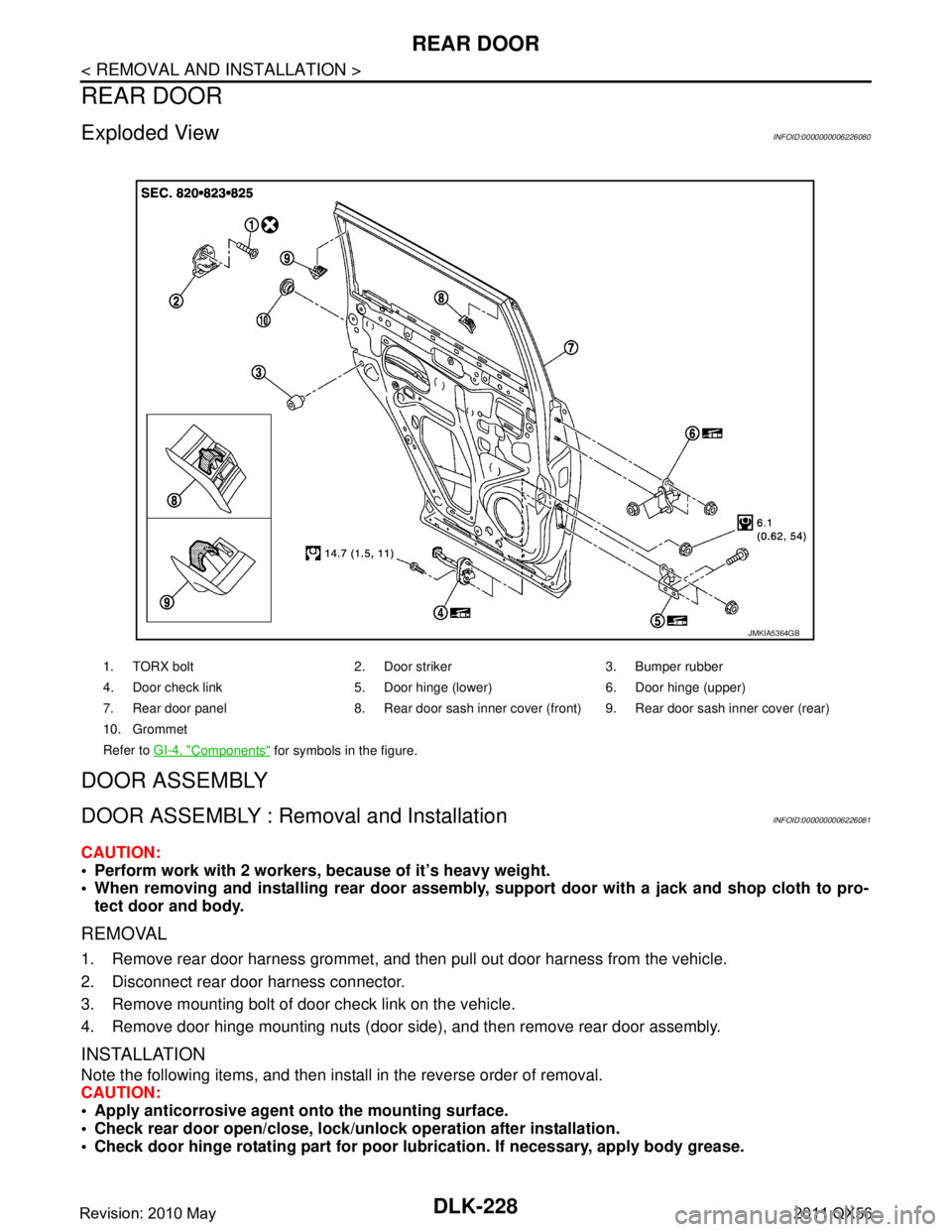
1. TORX bolt 2. Door striker 3. Bumper rubber
4. Door check link 5. Door hinge (lower) 6. Door hinge (upper)
7. Rear door panel 8. Rear door sash inner cove r (front) 9. Rear door sash inner cover (rear)
10. Grommet
Refer to GI-4, "
Components" for symbols in the figure.
JMKIA5364GB
Revision: 2010 May2011 QX56
Page 1766 of 5598
DLK-230
< REMOVAL AND INSTALLATION >
REAR DOOR
1. Remove center pillar lower garnish. Refer to INT-22, "CENTER PILLAR LOWER GARNISH : Removal
and Installation".
2. Loosen door hinge mounting nuts on door side.
3. Adjust the surface height of rear door according to the fitting standard dimension.
4. Temporarily tighten door hinge mounting nuts on door side.
5. Loosen door hinge mounting nuts and bolts on body side.
6. Raise rear door at rear end to adjust clearance of rear door according to the fitting standard dimension.
7. After adjustment tighten bolts and nuts to the specified torque. CAUTION:
After installation, apply touch-up paint (the bo dy color) onto the head of hinge mounting bolts
and nuts.
Check door hinge rotating part for poor lubrication. If necessary, apply body grease.
8. Install center pillar lower garnish. Refer to INT-22, "
CENTER PILLAR LOWER GARNISH : Removal and
Installation".
DOOR STRIKER ADJUSTMENT
Adjust door striker so that it becomes parallel with door lock insertion direction.
DOOR STRIKER
DOOR STRIKER : Removal and InstallationINFOID:0000000006226083
REMOVAL
Remove TORX bolts, and then remove door striker.
INSTALLATION
Note the following items, and then install in the reverse order of removal.
CAUTION:
Check rear door open/c lose, after installation.
After installation, be sure to perf orm the fitting adjustment. Refer to DLK-229, "
DOOR ASSEMBLY :
Adjustment".
DOOR HINGE
DOOR HINGE : Removal and InstallationINFOID:0000000006226084
CAUTION:
Perform work with 2 workers, because of it’s heavy weight.
When removing and installing r ear door assembly, support door with a jack and shop cloth to pro-
tect door and body.
REMOVAL
1. Remove rear door assembly. Refer to DLK-228, "DOOR ASSEMBLY : Removal and Installation".
2. Remove center pillar lower garnish. Refer to INT-22, "
CENTER PILLAR LOWER GARNISH : Removal
and Installation".
3. Remove rear door hinge mounting bolts and nuts (body side), and then remove door hinge.
INSTALLATION
Note the following items, and then install in the reverse order of removal.
CAUTION:
Apply anticorrosive agent onto the mounting surface.
Check rear door open/close op eration after installation.
Check door hinge rotating pa rt for poor lubrication. If necessary, apply body grease.
When removing and inst alling rear door assembly, perform the fitting adjustment. Refer to DLK-229,
"DOOR ASSEMBLY : Adjustment".
After installing, apply the touch-up paint (the body color) onto the head of door hinge mounting nuts.
DOOR CHECK LINK
DOOR CHECK LINK : Removal and InstallationINFOID:0000000006226085
REMOVAL
Revision: 2010 May2011 QX56
Page 1769 of 5598
BACK DOORDLK-233
< REMOVAL AND INSTALLATION >
C
DE
F
G H
I
J
L
M A
B
DLK
N
O P
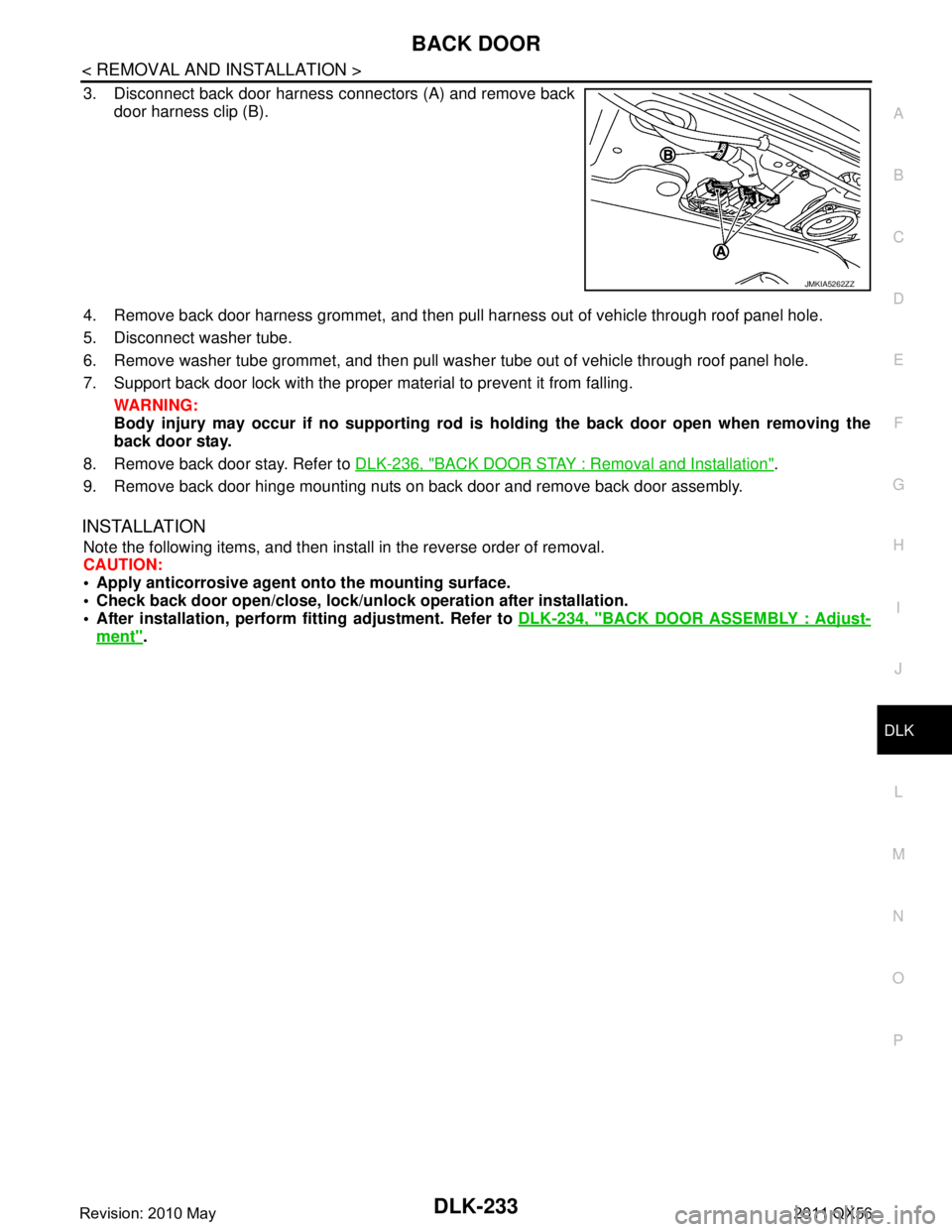
3. Disconnect back door harness connectors (A) and remove back door harness clip (B).
4. Remove back door harness grommet, and then pull harness out of vehicle through roof panel hole.
5. Disconnect washer tube.
6. Remove washer tube grommet, and then pull was her tube out of vehicle through roof panel hole.
7. Support back door lock with the proper material to prevent it from falling. WARNING:
Body injury may occur if no sup porting rod is holding the back door open when removing the
back door stay.
8. Remove back door stay. Refer to DLK-236, "
BACK DOOR STAY : Removal and Installation".
9. Remove back door hinge mounting nuts on back door and remove back door assembly.
INSTALLATION
Note the following items, and then install in the reverse order of removal.
CAUTION:
Apply anticorrosive agen t onto the mounting surface.
Check back door open/close, lock/un lock operation after installation.
After installation, perform fitting adjustment. Refer to DLK-234, "
BACK DOOR ASSEMBLY : Adjust-
ment".
JMKIA5262ZZ
Revision: 2010 May2011 QX56