2011 INFINITI QX56 steering wheel adjustment
[x] Cancel search: steering wheel adjustmentPage 2943 of 5598
FSU-1
SUSPENSION
C
DF
G H
I
J
K L
M
SECTION FSU
A
B
FSU
N
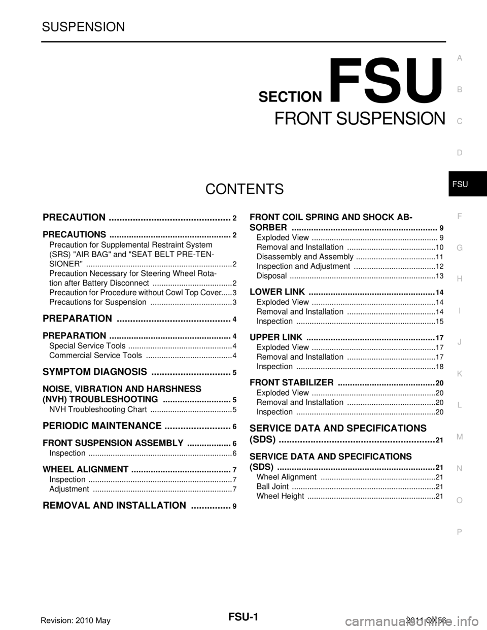
O PCONTENTS
FRONT SUSPENSION
PRECAUTION ................ ...............................2
PRECAUTIONS .............................................. .....2
Precaution for Supplemental Restraint System
(SRS) "AIR BAG" and "SEAT BELT PRE-TEN-
SIONER" ............................................................. ......
2
Precaution Necessary for Steering Wheel Rota-
tion after Battery Disconnect .....................................
2
Precaution for Procedure without Cowl Top Cover ......3
Precautions for Suspension ......................................3
PREPARATION ............................................4
PREPARATION .............................................. .....4
Special Service Tools .......................................... ......4
Commercial Service Tools ........................................4
SYMPTOM DIAGNOSIS ...............................5
NOISE, VIBRATION AND HARSHNESS
(NVH) TROUBLESHOOTING ........................ .....
5
NVH Troubleshooting Chart ................................ ......5
PERIODIC MAINTENANCE ..........................6
FRONT SUSPENSION ASSEMBLY .............. .....6
Inspection ............................................................ ......6
WHEEL ALIGNMENT ..........................................7
Inspection ............................................................ ......7
Adjustment ................................................................7
REMOVAL AND INSTALLATION ................9
FRONT COIL SPRING AND SHOCK AB-
SORBER ............................................................
9
Exploded View ..................................................... .....9
Removal and Installation .........................................10
Disassembly and Assembly .....................................11
Inspection and Adjustment ......................................12
Disposal ...................................................................13
LOWER LINK ....................................................14
Exploded View .........................................................14
Removal and Installation .........................................14
Inspection ................................................................15
UPPER LINK ......................... ............................17
Exploded View ..................................................... ....17
Removal and Installation .........................................17
Inspection ................................................................18
FRONT STABILIZER ........................................20
Exploded View .........................................................20
Removal and Installation .........................................20
Inspection ................................................................20
SERVICE DATA AND SPECIFICATIONS
(SDS) ............... .............................................
21
SERVICE DATA AND SPECIFICATIONS
(SDS) .................................................................
21
Wheel Alignment ................................................. ....21
Ball Joint ..................................................................21
Wheel Height ...........................................................21
Revision: 2010 May2011 QX56
Page 2949 of 5598
WHEEL ALIGNMENTFSU-7
< PERIODIC MAINTENANCE >
C
DF
G H
I
J
K L
M A
B
FSU
N
O P
WHEEL ALIGNMENT
InspectionINFOID:0000000006225640
DESCRIPTION
Measure wheel alignment under unladen conditions.
NOTE:
“Unladen conditions” means that fuel, engine coolant, and lubricant are full. Spare tire, jack, hand tools and
mats are in designated positions.
PRELIMINARY CHECK
Check the following:
Tires for improper air pressure and wear
Road wheels for runout: Refer to WT-64, "
Inspection".
Wheel bearing axial end play: Refer to FA X - 7 , "
Inspection" (2WD), FAX-16, "Inspection" (4WD).
Lower link and upper link ball joint axial end play: Refer to FSU-15, "
Inspection" and FSU-18, "Inspection".
Shock absorber operation.
Each mounting part of axle and suspension for looseness and deformation
Lower link for cracks, deformation and other damage
Vehicle height (posture)
GENERAL INFORMATION AND RECOMMENDATIONS
A four-wheel thrust alignment should be performed.
- This type of alignment is recomm ended for any NISSAN/INFINITI vehicle.
- The four-wheel “thrust” process helps ensure that t he vehicle is properly aligned and the steering wheel is
centered.
- The alignment rack itself should be capable of accepting any NISSAN/INFINITI vehicle.
- The rack should be checked to ensure that it is level.
Make sure the machine is properly calibrated.
- Your alignment equipment should be regularly ca librated in order to give correct information.
- Check with the manufacturer of your specific equi pment for their recommended Service/Calibration Sched-
ule.
ALIGNMENT PROCESS
IMPORTANT:
Use only the alignment specificati ons listed in this Service Manual.
When displaying the alignment settings, many alignment machines use “indicators”: (Green/red, plus or
minus, Go/No Go). Never use these indicators.
- The alignment specifications programmed into your machine that operate these indicators may not be cor-
rect.
- This may result in an ERROR.
Some newer alignment machines are equipped with an optional “Rolling Compensation” method to “com-
pensate” the sensors (alignment targets or head units). Never use this “Rolling Compensation” method.
- Use the “Jacking Compensation Method”. After installi ng the alignment targets or head units, raise the vehi-
cle and rotate the wheels 1/2 turn both ways.
- See Instructions in the alignment machine you're using for more information on this.
AdjustmentINFOID:0000000006225641
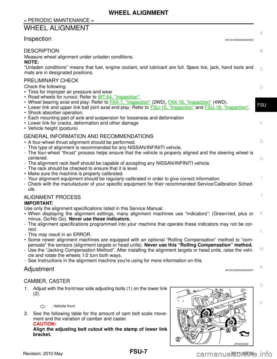
CAMBER, CASTER
1. Adjust with the front/rear side adjusting bolts (1) on the lower link
(2).
2. See the following table for the amount of cam bolt scale move- ment and the variation of camber and caster.
CAUTION:
Align the adjusting bolt cutout with the stamp of lower link
bracket.
: Vehicle front
JPEIA0235ZZ
Revision: 2010 May2011 QX56
Page 2958 of 5598
FSU-16
< REMOVAL AND INSTALLATION >
LOWER LINK
2. Move tip of ball stud in axial direction to check for looseness.
If axial end play exceeds standard range, replace lower link assembly.
INSPECTION AFTER INSTALLATION
1. Check wheel sensor harness for proper connection. Refer to BRC-134, "FRONT WHEEL SENSOR :
Exploded View".
2. Check wheel alignment. Refer to FSU-7, "
Inspection".
3. Adjust neutral position of steering angle sensor. Refer to BRC-64, "
Work Procedure".
4. Adjust levelizer adjustment of height sensor. Refer to EXL-61, "
LEVELIZER ADJUSTMENT : Special
Repair Requirement".
Axial end play : Refer to
FSU-21, "
Ball Joint".
Revision: 2010 May2011 QX56
Page 3030 of 5598
GW-1
BODY EXTERIOR, DOORS, ROOF & VEHICLE SECURITY
C
D
E
F
G H
I
J
L
M
SECTION GW
A
B
GW
N
O P
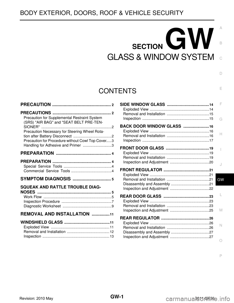
CONTENTS
GLASS & WINDOW SYSTEM
PRECAUTION ................ ...............................2
PRECAUTIONS .............................................. .....2
Precaution for Supplemental Restraint System
(SRS) "AIR BAG" and "SEAT BELT PRE-TEN-
SIONER" ............................................................. ......
2
Precaution Necessary for Steering Wheel Rota-
tion after Battery Disconnect .....................................
2
Precaution for Procedure without Cowl Top Cover ......3
Handling for Adhesive and Primer ............................3
PREPARATION ............................................4
PREPARATION .............................................. .....4
Special Service Tools ........................................ ......4
Commercial Service Tools .......................................4
SYMPTOM DIAGNOSIS ...............................5
SQUEAK AND RATTLE TROUBLE DIAG-
NOSES ........................ ........................................
5
Work Flow ........................................................... ......5
Inspection Procedure ................................................7
Diagnostic Worksheet ...............................................9
REMOVAL AND INSTALLATION ...............11
WINDSHIELD GLASS .................................... ....11
Exploded View .................................................... ....11
Removal and Installation .........................................12
Inspection ................................................................13
SIDE WINDOW GLASS ....................................14
Exploded View ..................................................... ....14
Removal and Installation .........................................15
Inspection ................................................................15
BACK DOOR WINDOW GLASS ......................16
Exploded View ..................................................... ....16
Removal and Installation .........................................16
Inspection ................................................................17
FRONT DOOR GLASS .....................................19
Exploded View .........................................................19
Removal and Installation .........................................19
Inspection and Adjustment ......................................20
FRONT REGULATOR .......................................21
Exploded View .........................................................21
Removal and Installation .........................................21
Disassembly and Assembly .....................................21
Inspection and Adjustment ......................................22
REAR DOOR GLASS .......................................23
Exploded View .........................................................23
Removal and Installation .........................................23
Inspection and Adjustment ......................................25
REAR REGULATOR .........................................26
Exploded View .........................................................26
Removal and Installation .........................................26
Disassembly and Assembly .....................................27
Inspection and Adjustment ......................................27
Revision: 2010 May2011 QX56
Page 3353 of 5598
INT-4
< PRECAUTION >
PRECAUTIONS
5. When the repair work is completed, re-connect both battery cables. With the brake pedal released, turn
the push-button ignition switch from ACC position to ON position, then to LOCK position. (The steering
wheel will lock when the push-button igniti on switch is turned to LOCK position.)
6. Perform self-diagnosis check of all control units using CONSULT-III.
Precaution for Procedure without Cowl Top CoverINFOID:0000000006415651
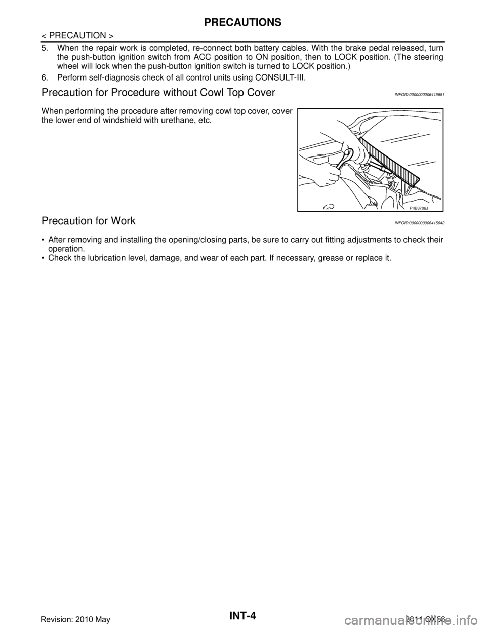
When performing the procedure after removing cowl top cover, cover
the lower end of windshield with urethane, etc.
Precaution for WorkINFOID:0000000006415642
After removing and installing the opening/closing parts, be sure to carry out fitting adjustments to check their
operation.
Check the lubrication level, damage, and wear of each part. If necessary, grease or replace it.
PIIB3706J
Revision: 2010 May2011 QX56
Page 4205 of 5598
REAR WHEEL HUB AND HOUSINGRAX-9
< REMOVAL AND INSTALLATION >
CEF
G H
I
J
K L
M A
B
RAX
N
O P
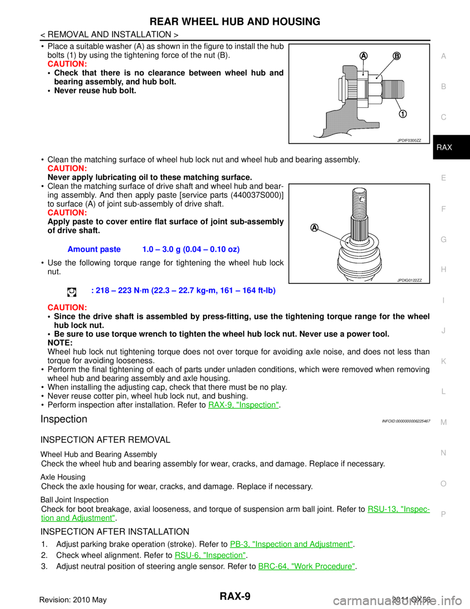
Place a suitable washer (A) as shown in the figure to install the hub bolts (1) by using the tightening force of the nut (B).
CAUTION:
Check that there is no cl earance between wheel hub and
bearing assembly, and hub bolt.
Never reuse hub bolt.
Clean the matching surface of wheel hub lock nut and wheel hub and bearing assembly. CAUTION:
Never apply lubricating oi l to these matching surface.
Clean the matching surface of drive shaft and wheel hub and bear-
ing assembly. And then apply paste [service parts (440037S000)]
to surface (A) of joint sub-assembly of drive shaft.
CAUTION:
Apply paste to cover entire fl at surface of joint sub-assembly
of drive shaft.
Use the following torque range for tightening the wheel hub lock nut.
CAUTION:
Since the drive shaft is assembled by press-fitting , use the tightening torque range for the wheel
hub lock nut.
Be sure to use torque wrench to tighten th e wheel hub lock nut. Never use a power tool.
NOTE:
Wheel hub lock nut tightening torque does not over tor que for avoiding axle noise, and does not less than
torque for avoiding looseness.
Perform the final tightening of each of parts under unladen conditions, which were removed when removing wheel hub and bearing assembly and axle housing.
When installing the adjusting cap, check that there must be no play.
Never reuse cotter pin, wheel hub lock nut, and bushing.
Perform inspection after installation. Refer to RAX-9, "
Inspection".
InspectionINFOID:0000000006225467
INSPECTION AFTER REMOVAL
Wheel Hub and Bearing Assembly
Check the wheel hub and bearing assembly for wear, cracks, and damage. Replace if necessary.
Axle Housing
Check the axle housing for wear, cracks, and damage. Replace if necessary.
Ball Joint Inspection
Check for boot breakage, axial looseness, and torque of suspension arm ball joint. Refer to RSU-13, "Inspec-
tion and Adjustment".
INSPECTION AFTER INSTALLATION
1. Adjust parking brake operation (stroke). Refer to PB-3, "Inspection and Adjustment".
2. Check wheel alignment. Refer to RSU-6, "
Inspection".
3. Adjust neutral position of steering angle sensor. Refer to BRC-64, "
Work Procedure".
JPDIF0300ZZ
Amount paste 1.0 – 3.0 g (0.04 – 0.10 oz)
: 218 – 223 N·m (22.3 – 22.7 kg-m, 161 – 164 ft-lb)
JPDIG0122ZZ
Revision: 2010 May2011 QX56
Page 4213 of 5598
REAR DRIVE SHAFTRAX-17
< REMOVAL AND INSTALLATION >
CEF
G H
I
J
K L
M A
B
RAX
N
O P
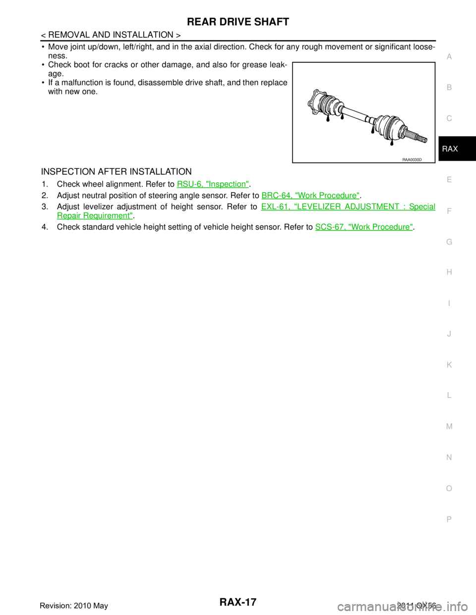
Move joint up/down, left/right, and in the axial directi on. Check for any rough movement or significant loose-
ness.
Check boot for cracks or other damage, and also for grease leak-
age.
If a malfunction is found, disassem ble drive shaft, and then replace
with new one.
INSPECTION AFTER INSTALLATION
1. Check wheel alignment. Refer to RSU-6, "Inspection".
2. Adjust neutral position of steering angle sensor. Refer to BRC-64, "
Work Procedure".
3. Adjust levelizer adjustment of height sensor. Refer to EXL-61, "
LEVELIZER ADJUSTMENT : Special
Repair Requirement".
4. Check standard vehicle height setting of vehicle height sensor. Refer to SCS-67, "
Work Procedure".
RAA0030D
Revision: 2010 May2011 QX56
Page 4261 of 5598
RSU-6
< PERIODIC MAINTENANCE >
WHEEL ALIGNMENT
WHEEL ALIGNMENT
InspectionINFOID:0000000006225661
DESCRIPTION
Measure wheel alignment under unladen conditions.
NOTE:
“Unladen conditions” means that fuel, engine coolant, and lubricant are full. Spare tire, jack, hand tools and
mats are in designated positions.
PRELIMINARY CHECK
Check the following:
Tires for improper air pressure and wear
Road wheels for runout. Refer to WT-64, "
Inspection".
Wheel bearing axial end play. Refer to RAX-5, "
Inspection".
Ball joint axial end play of suspension arm and front lower link. Refer to RSU-20, "
Ball Joint".
Shock absorber operation
Each mounting point of axle and suspension for looseness and deformation
Each of front lower link, rear lower link, rear suspension member, suspension arm and shock absorber for
cracks, deformation, and other damage
Vehicle height (posture)
GENERAL INFORMATION AND RECOMMENDATIONS
A four-wheel thrust alignment should be performed.
- This type of alignment is recomm ended for any NISSAN/INFINITI vehicle.
- The four-wheel “thrust” process helps ensure that t he vehicle is properly aligned and the steering wheel is
centered.
- The alignment rack itself should be capable of accepting any NISSAN/INFINITI vehicle.
- The rack should be checked to ensure that it is level.
Make sure the machine is properly calibrated.
- Your alignment equipment should be regularly calib rated in order to give correct information.
- Check with the manufacturer of your specific equi pment for their recommended Service/Calibration Sched-
ule.
ALIGNMENT PROCESS
IMPORTANT:
Use only the alignment specifications listed in this Service Manual.
When displaying the alignment settings, many alignment machines use “indicators”: (Green/red, plus or
minus, Go/No Go). Never use these indicators.
- The alignment specifications programmed into your machine that operate these indicators may not be cor-
rect.
- This may result in an ERROR.
Some newer alignment machines are equipped with an optional “Rolling Compensation” method to “com- pensate” the sensors (alignment targets or head units). Never use this “Rolling Compensation” method.
- Use the “Jacking Compensation Method”. After installi ng the alignment targets or head units, raise the vehi-
cle and rotate the wheels 1/2 turn both ways.
- See Instructions in the alignment machine you're using for more information on this.
AdjustmentINFOID:0000000006225662
CAMBER
Revision: 2010 May2011 QX56