2011 INFINITI QX56 mileage
[x] Cancel search: mileagePage 2586 of 5598
EM-24
< PERIODIC MAINTENANCE >
SPARK PLUG
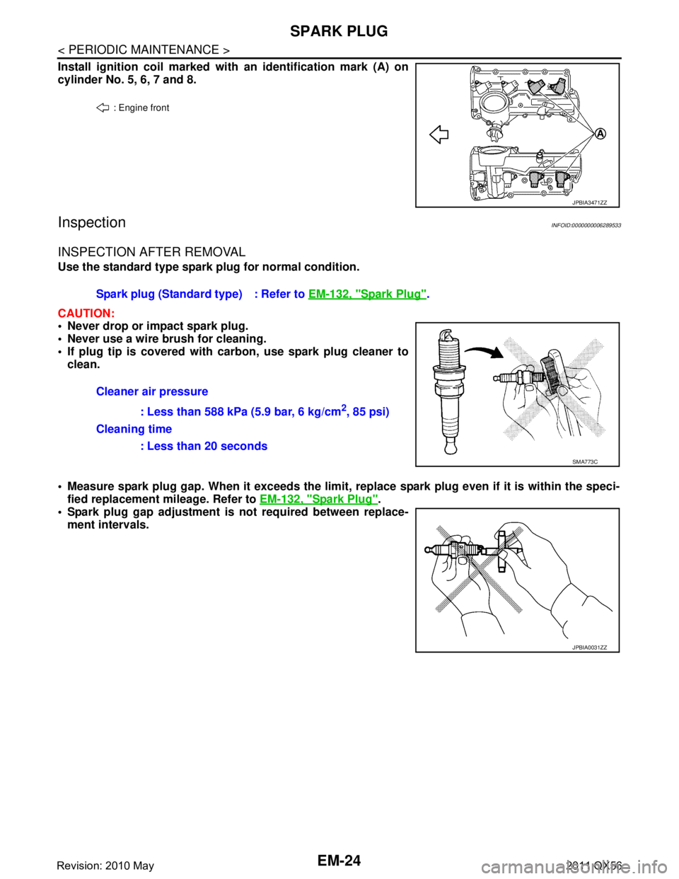
Install ignition coil marked with an identification mark (A) on
cylinder No. 5, 6, 7 and 8.
InspectionINFOID:0000000006289533
INSPECTION AFTER REMOVAL
Use the standard type spark plug for normal condition.
CAUTION:
Never drop or impact spark plug.
Never use a wire brush for cleaning.
If plug tip is covered with carbon, use spark plug cleaner to clean.
Measure spark plug gap. When it exceeds the limit, replace spark plug even if it is within the speci-
fied replacement mileage. Refer to EM-132, "
Spark Plug".
Spark plug gap adjustment is not required between replace-
ment intervals.
: Engine front
JPBIA3471ZZ
Spark plug (Standard type) : Refer to EM-132, "Spark Plug".
Cleaner air pressure : Less than 588 kPa (5.9 bar, 6 kg/cm
2, 85 psi)
Cleaning time : Less than 20 seconds
SMA773C
JPBIA0031ZZ
Revision: 2010 May2011 QX56
Page 2733 of 5598
![INFINITI QX56 2011 Factory Service Manual
DIAGNOSIS SYSTEM (BCM)EXL-23
< SYSTEM DESCRIPTION > [XENON TYPE]
C
D
E
F
G H
I
J
K
M A
B
EXL
N
O P
HEADLAMP
HEADLAMP : CONSULT-III Func tion (BCM - HEAD LAMP)INFOID:0000000006213911
WORK SUPPORT
CONS INFINITI QX56 2011 Factory Service Manual
DIAGNOSIS SYSTEM (BCM)EXL-23
< SYSTEM DESCRIPTION > [XENON TYPE]
C
D
E
F
G H
I
J
K
M A
B
EXL
N
O P
HEADLAMP
HEADLAMP : CONSULT-III Func tion (BCM - HEAD LAMP)INFOID:0000000006213911
WORK SUPPORT
CONS](/manual-img/42/57033/w960_57033-2732.png)
DIAGNOSIS SYSTEM (BCM)EXL-23
< SYSTEM DESCRIPTION > [XENON TYPE]
C
D
E
F
G H
I
J
K
M A
B
EXL
N
O P
HEADLAMP
HEADLAMP : CONSULT-III Func tion (BCM - HEAD LAMP)INFOID:0000000006213911
WORK SUPPORT
CONSULT screen item Indication/Unit Description
Vehicle Speed km/h Vehicle speed of the moment a particular DTC is detected
Odo/Trip Meter km Total mileage (Odometer value) of the moment a particular DTC is detected
Vehicle Condition SLEEP>LOCK
Power position status of
the moment a particular
DTC is detected While turning BCM status from low power consumption mode to
normal mode (Power supply position is “LOCK”)
SLEEP>OFF While turning BCM status from low power consumption mode to
normal mode (Power supply position is “OFF”.)
LOCK>ACC While turning power supply position from “LOCK” to “ACC”
ACC>ON While turning power supply position from “ACC” to “IGN”
RUN>ACC While turning power supply position
from “RUN” to “ACC” (Vehicle
is stopping and selector lever is except P position.)
CRANK>RUN While turning power su
pply position from “CRANKING” to “RUN”
(From cranking up the engine to run it)
RUN>URGENT While turning power su
pply position from “RUN“ to “ACC” (Emer-
gency stop operation)
ACC>OFF While turning power supply position from “ACC” to “OFF”
OFF>LOCK While turning power supply position from “OFF” to “LOCK”
OFF>ACC While turning power supply position from “OFF” to “ACC”
ON>CRANK While turning po wer supply position from “IGN” to “CRANKING”
OFF>SLEEP While turning BCM status from normal mode (Power supply posi-
tion is “OFF”.) to low power consumption mode
LOCK>SLEEP While turning BCM status from normal mode (Power supply posi-
tion is “LOCK”.) to low power consumption mode
LOCK Power supply position is “LOCK” (Ignition switch OFF with steer-
ing is locked.)
OFF Power supply position
is “OFF” (Ignition switch OFF with steering
is unlocked.)
ACC Power supply position is “ACC” (Ignition switch ACC)
ON Power supply position is “IGN” (Ignition switch ON with engine
stopped)
ENGINE RUN Power supply posi
tion is “RUN” (Ignition switch ON with engine
running)
CRANKING Power supply position is “CRANKING” (At engine cranking)
IGN Counter 0 - 39 The number of times that ignition switch is turned ON after DTC is detected
The number is 0 when a malfunction is detected now.
The number increases like 1
→ 2 → 3...38 → 39 after returning to the normal condition
whenever ignition switch OFF → ON.
The number is fixed to 39 until the self-diagnosis results are erased if it is over 39.
Service item Setting item Setting
CUSTOM A/LIGHT SETTING MODE 1*
1Normal
MODE 2 More sensitive setting than normal setting (Turns ON earlier than normal opera-
tion)
MODE 3 More sensitive setting than MODE 2 (Turns ON earlier than MODE 2)
MODE 4 Less sensitive setting than normal setting (Turns ON later than normal operation)
Revision: 2010 May2011 QX56
Page 3280 of 5598

DIAGNOSIS SYSTEM (BCM)INL-13
< SYSTEM DESCRIPTION >
C
DE
F
G H
I
J
K
M A
B
INL
N
O P
INT LAMP
CONSULT screen item Indication/Unit Description
Vehicle Speed km/h Vehicle speed of the moment a particular DTC is detected
Odo/Trip Meter km Total mileage (Odometer value) of the moment a particular DTC is detected
Vehicle Condition SLEEP>LOCK
Power position status of
the moment a particular
DTC is detected While turning BCM status from low power consumption mode to
normal mode (Power supply position is “LOCK”)
SLEEP>OFF While turning BCM status from low power consumption mode to
normal mode (Power supply position is “OFF”.)
LOCK>ACC While turning power supply position from “LOCK” to “ACC”
ACC>ON While turning power supply position from “ACC” to “IGN”
RUN>ACC While turning power supply position
from “RUN” to “ACC” (Vehicle
is stopping and selector lever is except P position.)
CRANK>RUN While turning power su
pply position from “CRANKING” to “RUN”
(From cranking up the engine to run it)
RUN>URGENT While turning power su
pply position from “RUN“ to “ACC” (Emer-
gency stop operation)
ACC>OFF While turning power supply position from “ACC” to “OFF”
OFF>LOCK While turning power supply position from “OFF” to “LOCK”
OFF>ACC While turning power supply position from “OFF” to “ACC”
ON>CRANK While turning po wer supply position from “IGN” to “CRANKING”
OFF>SLEEP While turning BCM status from normal mode (Power supply posi-
tion is “OFF”.) to low power consumption mode
LOCK>SLEEP While turning BCM status from normal mode (Power supply posi-
tion is “LOCK”.) to low power consumption mode
LOCK Power supply position is “LOCK” (Ignition switch OFF with steer-
ing is locked.)
OFF Power supply position
is “OFF” (Ignition switch OFF with steering
is unlocked.)
ACC Power supply position is “ACC” (Ignition switch ACC)
ON Power supply position is “IGN” (Ignition switch ON with engine
stopped)
ENGINE RUN Power supply posi
tion is “RUN” (Ignition switch ON with engine
running)
CRANKING Power supply position is “CRANKING” (At engine cranking)
IGN Counter 0 - 39 The number of times that ignition switch is turned ON after DTC is detected
The number is 0 when a malfunction is detected now.
The number increases like 1
→ 2 → 3...38 → 39 after returning to the normal condition
whenever ignition switch OFF → ON.
The number is fixed to 39 until the self-diagnosis results are erased if it is over 39.
Revision: 2010 May2011 QX56
Page 3676 of 5598
MA-6
< PERIODIC MAINTENANCE >
PERIODIC MAINTENANCE
PERIODIC MAINTENANCE
Introduction of Periodic MaintenanceINFOID:0000000006287729
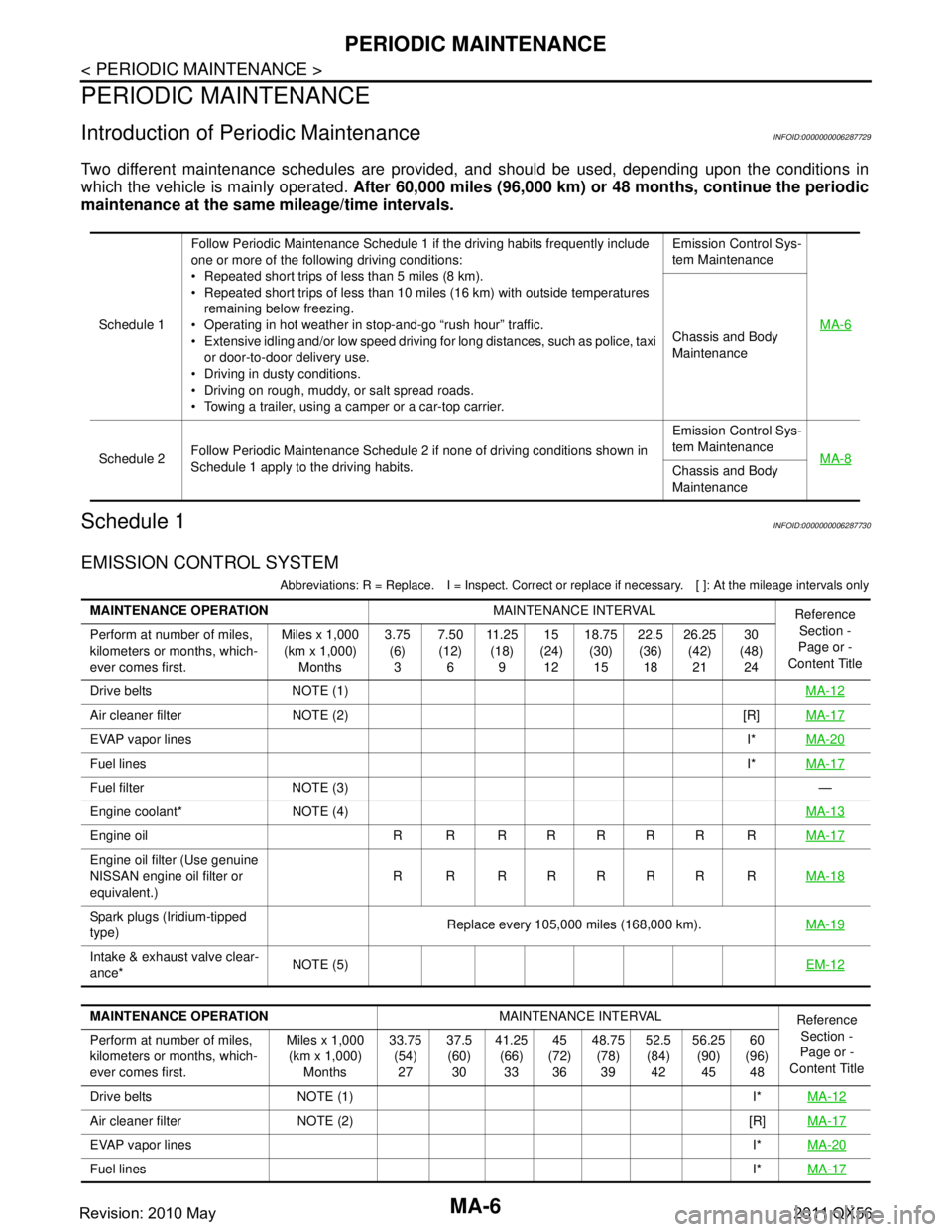
Two different maintenance schedules are provided, and should be used, depending upon the conditions in
which the vehicle is mainly operated. After 60,000 miles (96,000 km) or 48 months, continue the periodic
maintenance at the same mileage/time intervals.
Schedule 1INFOID:0000000006287730
EMISSION CONTROL SYSTEM
Abbreviations: R = Replace. I = Inspec t. Correct or replace if necessary. [ ]: At the mileage intervals only
Schedule 1Follow Periodic Maintenance Schedule 1 if the driving habits frequently include
one or more of the following driving conditions:
Repeated short trips of less than 5 miles (8 km).
Repeated short trips of less than 10 miles (16 km) with outside temperatures
remaining below freezing.
Operating in hot weather in stop-and-go “rush hour” traffic.
Extensive idling and/or low speed driving for long distances, such as police, taxi
or door-to-door delivery use.
Driving in dusty conditions.
Driving on rough, muddy, or salt spread roads.
Towing a trailer, using a camper or a car-top carrier. Emission Control Sys-
tem Maintenance
MA-6Chassis and Body
Maintenance
Schedule 2 Follow Periodic Maintenance Schedule 2 if none of driving conditions shown in
Schedule 1 apply to the driving habits. Emission Control Sys-
tem Maintenance
MA-8
Chassis and Body
Maintenance
MAINTENANCE OPERATION MAINTENANCE INTERVAL
Reference
Section -
Page or -
Content Title
Perform at number of miles,
kilometers or months, which-
ever comes first. Miles x 1,000
(km x 1,000) Months 3.75
(6)3 7.50
(12) 6 11 . 2 5
(18) 9 15
(24) 12 18.75
(30)15 22.5
(36) 18 26.25
(42)21 30
(48) 24
Drive belts NOTE (1) MA-12
Air cleaner filter NOTE (2) [R]MA-17
EVAP vapor linesI*MA-20
Fuel lines I*MA-17
Fuel filter NOTE (3) —
Engine coolant* NOTE (4) MA-13
Engine oil R R R R R R R RMA-17
Engine oil filter (Use genuine
NISSAN engine oil filter or
equivalent.)R R RRRRR R
MA-18
Spark plugs (Iridium-tipped
type)Replace every 105,000 miles (168,000 km).
MA-19
Intake & exhaust valve clear-
ance*NOTE (5)
EM-12
MAINTENANCE OPERATIONMAINTENANCE INTERVAL
Reference
Section -
Page or -
Content Title
Perform at number of miles,
kilometers or months, which-
ever comes first. Miles x 1,000
(km x 1,000) Months 33.75
(54)27 37.5
(60) 30 41.25
(66)33 45
(72) 36 48.75
(78)39 52.5
(84) 42 56.25
(90)45 60
(96) 48
Drive belts NOTE (1) I* MA-12
Air cleaner filter NOTE (2) [R]MA-17
EVAP vapor linesI*MA-20
Fuel lines I*MA-17
Revision: 2010 May2011 QX56
Page 3678 of 5598
MA-8
< PERIODIC MAINTENANCE >
PERIODIC MAINTENANCE
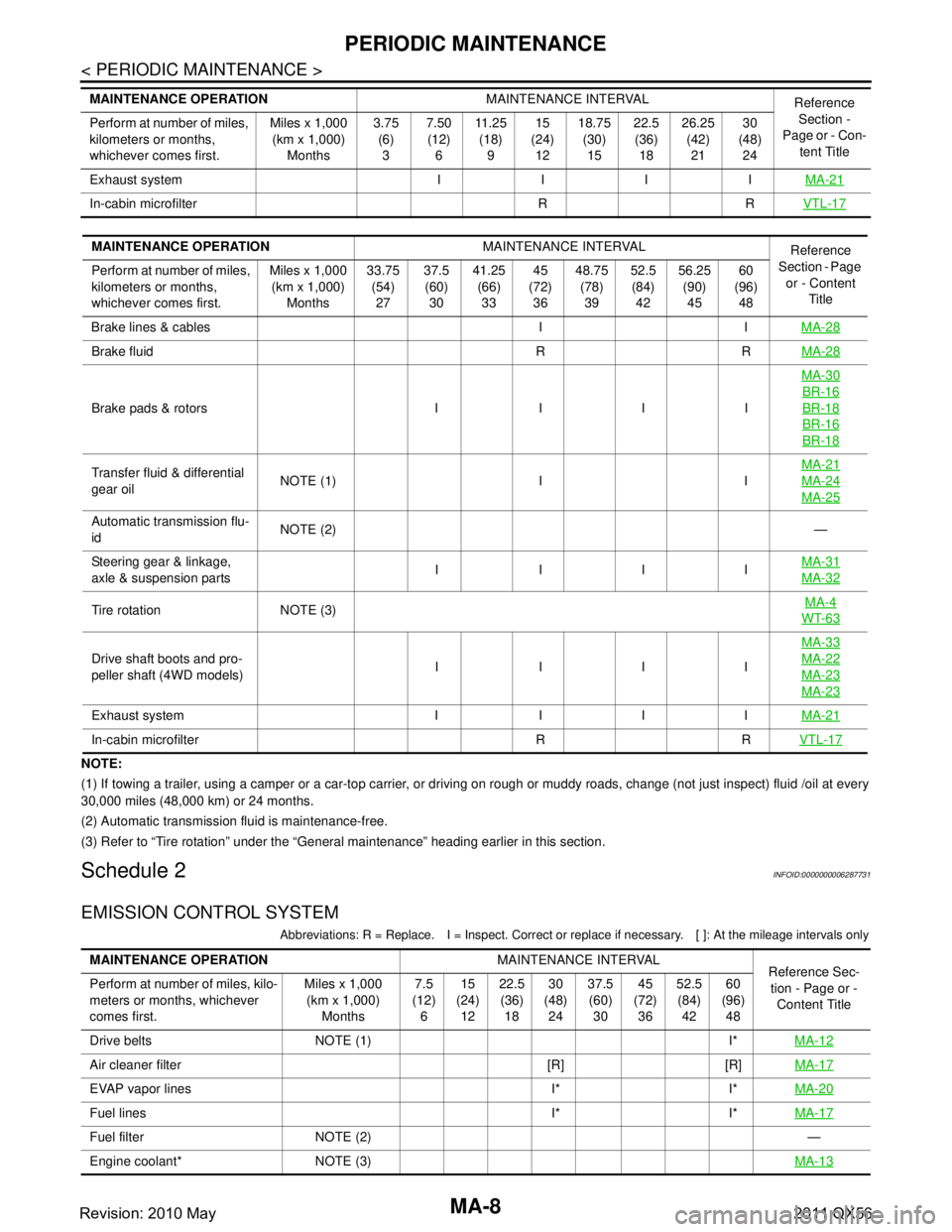
NOTE:
(1) If towing a trailer, using a camper or a car-top carrier, or driving on rough or muddy roads, change (not just inspect) fluid /oil at every
30,000 miles (48,000 km) or 24 months.
(2) Automatic transmission fluid is maintenance-free.
(3) Refer to “Tire rotation” unde r the “General maintenance” heading earlier in this section.
Schedule 2INFOID:0000000006287731
EMISSION CONTROL SYSTEM
Abbreviations: R = Replace. I = Inspec t. Correct or replace if necessary. [ ]: At the mileage intervals only
Exhaust system I I I I MA-21
In-cabin microfilter R RVTL-17
MAINTENANCE OPERATIONMAINTENANCE INTERVAL
Reference
Section -
Page or - Con- tent Title
Perform at number of miles,
kilometers or months,
whichever comes first. Miles x 1,000
(km x 1,000)
Months 3.75
(6)
3 7.50
(12)
6 11 . 2 5
(18)
9 15
(24)
12 18.75
(30)
15 22.5
(36)
18 26.25
(42)
21 30
(48)
24
MAINTENANCE OPERATION MAINTENANCE INTERVAL
Reference
Section - Page
or - Content Title
Perform at number of miles,
kilometers or months,
whichever comes first. Miles x 1,000
(km x 1,000) Months 33.75
(54)27 37.5
(60) 30 41.25
(66)33 45
(72) 36 48.75
(78)39 52.5
(84) 42 56.25
(90)45 60
(96) 48
Brake lines & cables I I MA-28
Brake fluid R RMA-28
Brake pads & rotors I I I IMA-30
BR-16
BR-18
BR-16
BR-18
Transfer fluid & differential
gear oil
NOTE (1) I I MA-21MA-24
MA-25
Automatic transmission flu-
id
NOTE (2)
—
Steering gear & linkage,
axle & suspension parts IIII
MA-31
MA-32
Tire rotation NOTE (3) MA-4WT-63
Drive shaft boots and pro-
peller shaft (4WD models)IIII MA-33MA-22
MA-23
MA-23
Exhaust system I I I I
MA-21
In-cabin microfilter R RVTL-17
MAINTENANCE OPERATIONMAINTENANCE INTERVAL
Reference Sec-
tion - Page or -
Content Title
Perform at number of miles, kilo-
meters or months, whichever
comes first. Miles x 1,000
(km x 1,000)
Months 7.5
(12)
6 15
(24)
12 22.5
(36)
18 30
(48)
24 37.5
(60)
30 45
(72)
36 52.5
(84)
42 60
(96)
48
Drive belts NOTE (1) I* MA-12
Air cleaner filter [R] [R]MA-17
EVAP vapor lines I* I*MA-20
Fuel lines I* I*MA-17
Fuel filter NOTE (2) —
Engine coolant* NOTE (3) MA-13
Revision: 2010 May2011 QX56
Page 3689 of 5598
ENGINE MAINTENANCEMA-19
< PERIODIC MAINTENANCE >
C
DE
F
G H
I
J
K L
M B
MA
N
O A
SPARK PLUG : Removal and InstallationINFOID:0000000006394839
REMOVAL
1. Remove engine cover. Refer to
EM-25, "Exploded View".
2. Remove ignition coil. Refer to EM-29, "
Exploded View".
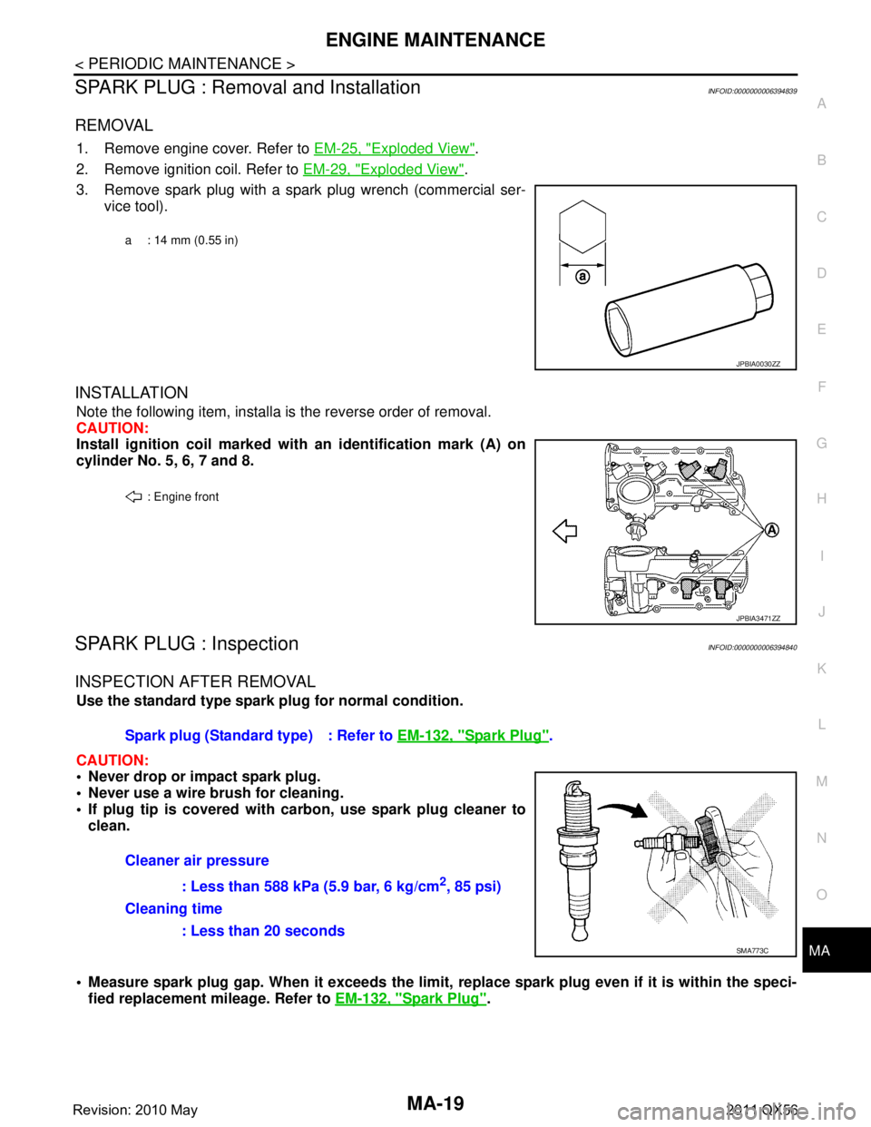
3. Remove spark plug with a spark plug wrench (commercial ser- vice tool).
INSTALLATION
Note the following item, installa is the reverse order of removal.
CAUTION:
Install ignition coil marked wi th an identification mark (A) on
cylinder No. 5, 6, 7 and 8.
SPARK PLUG : InspectionINFOID:0000000006394840
INSPECTION AFTER REMOVAL
Use the standard type spark plug for normal condition.
CAUTION:
Never drop or impact spark plug.
Never use a wire brush for cleaning.
If plug tip is covered with carbon, use spark plug cleaner to
clean.
Measure spark plug gap. When it exceeds the limit, replace spark plug even if it is within the speci-
fied replacement mileage. Refer to EM-132, "
Spark Plug".
a : 14 mm (0.55 in)
JPBIA0030ZZ
: Engine front
JPBIA3471ZZ
Spark plug (Standard type) : Refer to EM-132, "Spark Plug".
Cleaner air pressure : Less than 588 kPa (5.9 bar, 6 kg/cm
2, 85 psi)
Cleaning time
: Less than 20 seconds
SMA773C
Revision: 2010 May2011 QX56
Page 3754 of 5598
MWI
SYSTEMMWI-11
< SYSTEM DESCRIPTION >
C
DE
F
G H
I
J
K L
M B A
O P
ARRANGEMENT OF COMBINATION METER
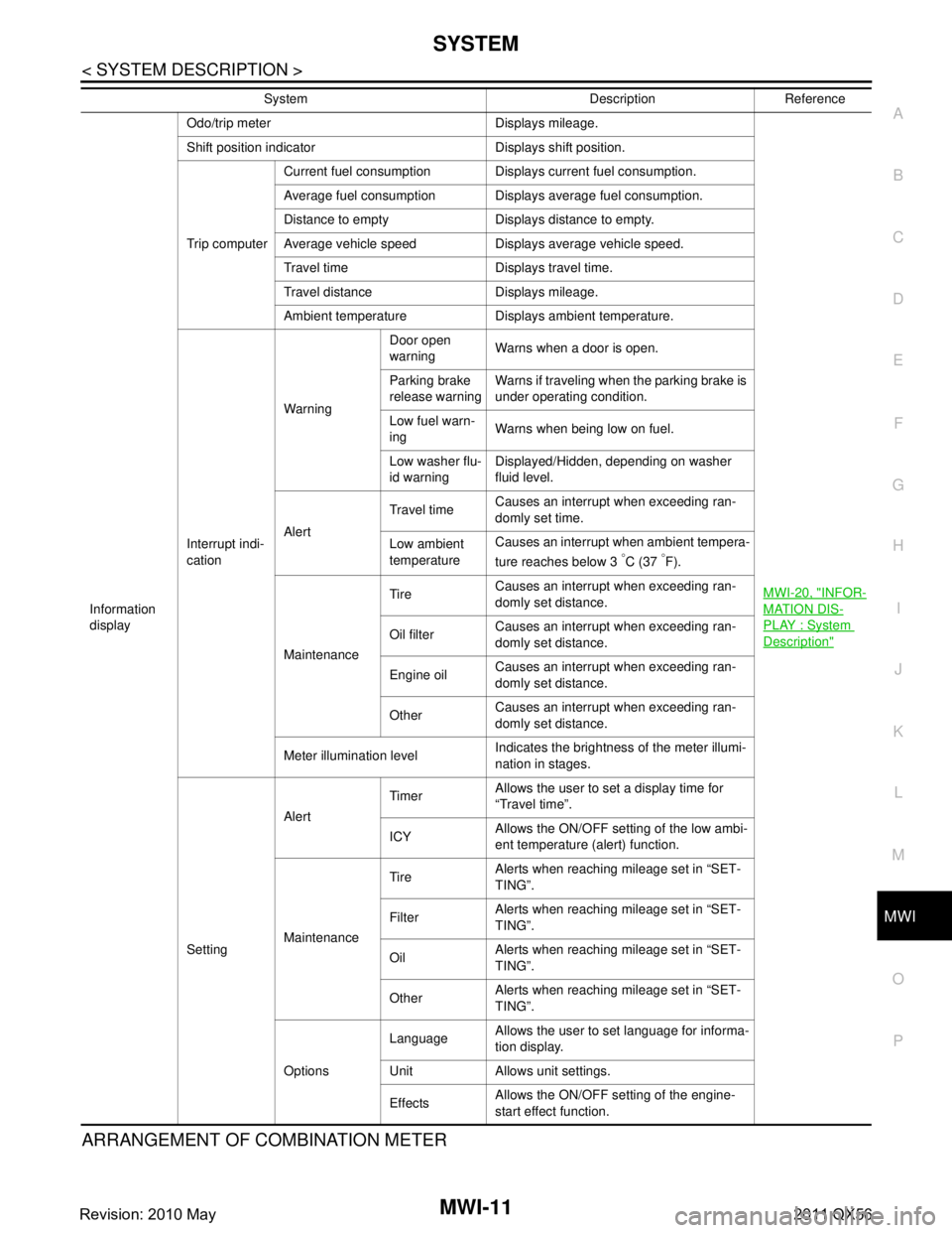
Information
display Odo/trip meter Displays mileage.
MWI-20, "
INFOR-
MATION DIS-
PLAY : System
Description"
Shift position indicator Displays shift position.
Trip computerCurrent fuel consumption Displays current fuel consumption.
Average fuel consumption Displays average fuel consumption.
Distance to empty Displays distance to empty.
Average vehicle speed Displays average vehicle speed.
Travel time Displays travel time.
Travel distance Displays mileage.
Ambient temperature Displays ambient temperature.
Interrupt indi-
cation Warning
Door open
warning
Warns when a door is open.
Parking brake
release warning Warns if traveling when the parking brake is
under operating condition.
Low fuel warn-
ing Warns when being low on fuel.
Low washer flu-
id warning Displayed/Hidden, depending on washer
fluid level.
Alert Travel time
Causes an interrupt when exceeding ran-
domly set time.
Low ambient
temperature Causes an interrupt when ambient tempera-
ture reaches below 3
°C (37 °F).
Maintenance Tire
Causes an interrupt when exceeding ran-
domly set distance.
Oil filter Causes an interrupt when exceeding ran-
domly set distance.
Engine oil Causes an interrupt when exceeding ran-
domly set distance.
Other Causes an interrupt when exceeding ran-
domly set distance.
Meter illumination level Indicates the brightness of the meter illumi-
nation in stages.
Setting Alert
Timer
Allows the user to set a display time for
“Travel time”.
ICY Allows the ON/OFF setting of the low ambi-
ent temperature (alert) function.
Maintenance Tire
Alerts when reaching mileage set in “SET-
TING”.
Filter Alerts when reaching mileage set in “SET-
TING”.
Oil Alerts when reaching mileage set in “SET-
TING”.
Other Alerts when reaching mileage set in “SET-
TING”.
Options Language
Allows the user to set language for informa-
tion display.
Unit Allows unit settings.
Effects Allows the ON/OFF setting of the engine-
start effect function.
System Description Reference
Revision: 2010 May2011 QX56
Page 3763 of 5598
MWI-20
< SYSTEM DESCRIPTION >
SYSTEM
INFORMATION DISPLAY : System Description
INFOID:0000000006221717
DESCRIPTION
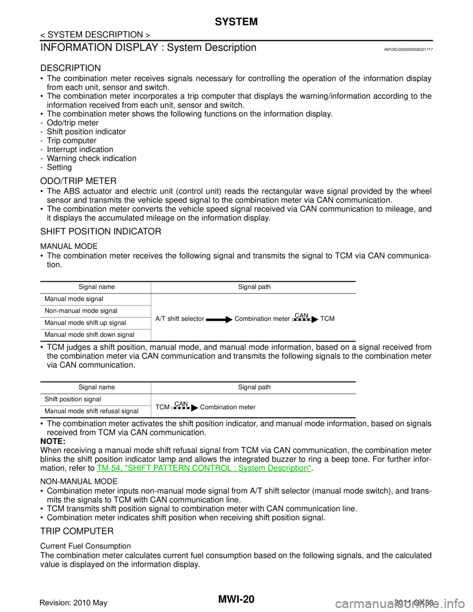
The combination meter receives signals necessary for controlling the operation of the information display from each unit, sensor and switch.
The combination meter incorporates a trip computer t hat displays the warning/information according to the
information received from each unit, sensor and switch.
The combination meter shows the following functions on the information display.
- Odo/trip meter
- Shift position indicator
- Trip computer
- Interrupt indication
- Warning check indication
- Setting
ODO/TRIP METER
The ABS actuator and electric unit (control unit) r eads the rectangular wave signal provided by the wheel
sensor and transmits the vehicle speed signal to the combination meter via CAN communication.
The combination meter converts the vehicle speed signal received via CAN communication to mileage, and it displays the accumulated mileage on the information display.
SHIFT POSITION INDICATOR
MANUAL MODE
The combination meter receives the following signal and transmits the signal to TCM via CAN communica-tion.
TCM judges a shift position, manual mode, and manual mode information, based on a signal received from
the combination meter via CAN communication and transmi ts the following signals to the combination meter
via CAN communication.
The combination meter activates the shift position indicator, and manual mode information, based on signals received from TCM via CAN communication.
NOTE:
When receiving a manual mode shift refusal signal from TCM via CAN communication, the combination meter
blinks the shift position indicator lamp and allows the integrated buzzer to ring a beep tone. For further infor-
mation, refer to TM-54, "
SHIFT PATTERN CONTROL : System Description".
NON-MANUAL MODE
Combination meter inputs non-manual mode signal from A/T shift selector (manual mode switch), and trans-
mits the signals to TCM with CAN communication line.
TCM transmits shift position signal to combination meter with CAN communication line.
Combination meter indicates shift position when receiving shift position signal.
TRIP COMPUTER
Current Fuel Consumption
The combination meter calculates current fuel cons umption based on the following signals, and the calculated
value is displayed on the information display.
Signal name Signal path
Manual mode signal
A/T shift selector Combination meter TCM
Non-manual mode signal
Manual mode shift up signal
Manual mode shift down signal
Signal name Signal path
Shift position signal TCM Combination meter
Manual mode shift refusal signal
Revision: 2010 May2011 QX56