2011 INFINITI QX56 hood open
[x] Cancel search: hood openPage 2876 of 5598

COWL TOPEXT-21
< REMOVAL AND INSTALLATION >
C
DE
F
G H
I
J
L
M A
B
EXT
N
O P
COWL TOP
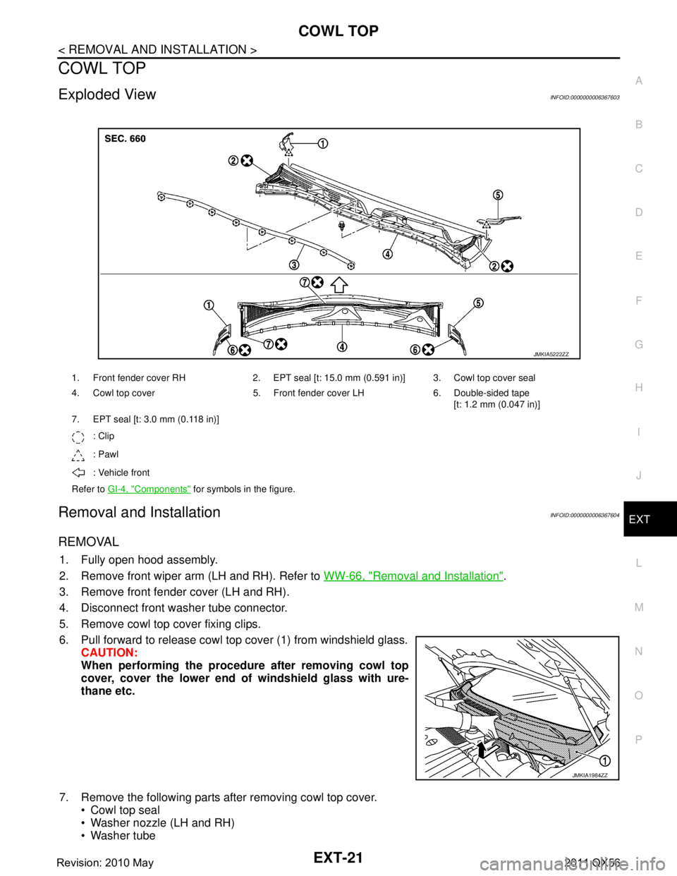
Exploded ViewINFOID:0000000006367603
Removal and InstallationINFOID:0000000006367604
REMOVAL
1. Fully open hood assembly.
2. Remove front wiper arm (LH and RH). Refer to WW-66, "
Removal and Installation".
3. Remove front fender cover (LH and RH).
4. Disconnect front wa sher tube connector.
5. Remove cowl top cover fixing clips.
6. Pull forward to release cowl top cover (1) from windshield glass. CAUTION:
When performing the procedur e after removing cowl top
cover, cover the lower end of windshield glass with ure-
thane etc.
7. Remove the following parts after removing cowl top cover. Cowl top seal
Washer nozzle (LH and RH)
Washer tube
1. Front fender cover RH 2. EPT seal [t: 15.0 mm (0.591 in)] 3. Cowl top cover seal
4. Cowl top cover 5. Front fender cover LH 6. Double-sided tape
[t: 1.2 mm (0.047 in)]
7. EPT seal [t: 3.0 mm (0.118 in)]
: Clip
: Pawl
: Vehicle front
Refer to GI-4, "
Components" for symbols in the figure.
JMKIA5222ZZ
JMKIA1984ZZ
Revision: 2010 May2011 QX56
Page 2975 of 5598

HOW TO READ WIRING DIAGRAMSGI-11
< HOW TO USE THIS MANUAL >
C
DE
F
G H
I
J
K L
M B
GI
N
O P
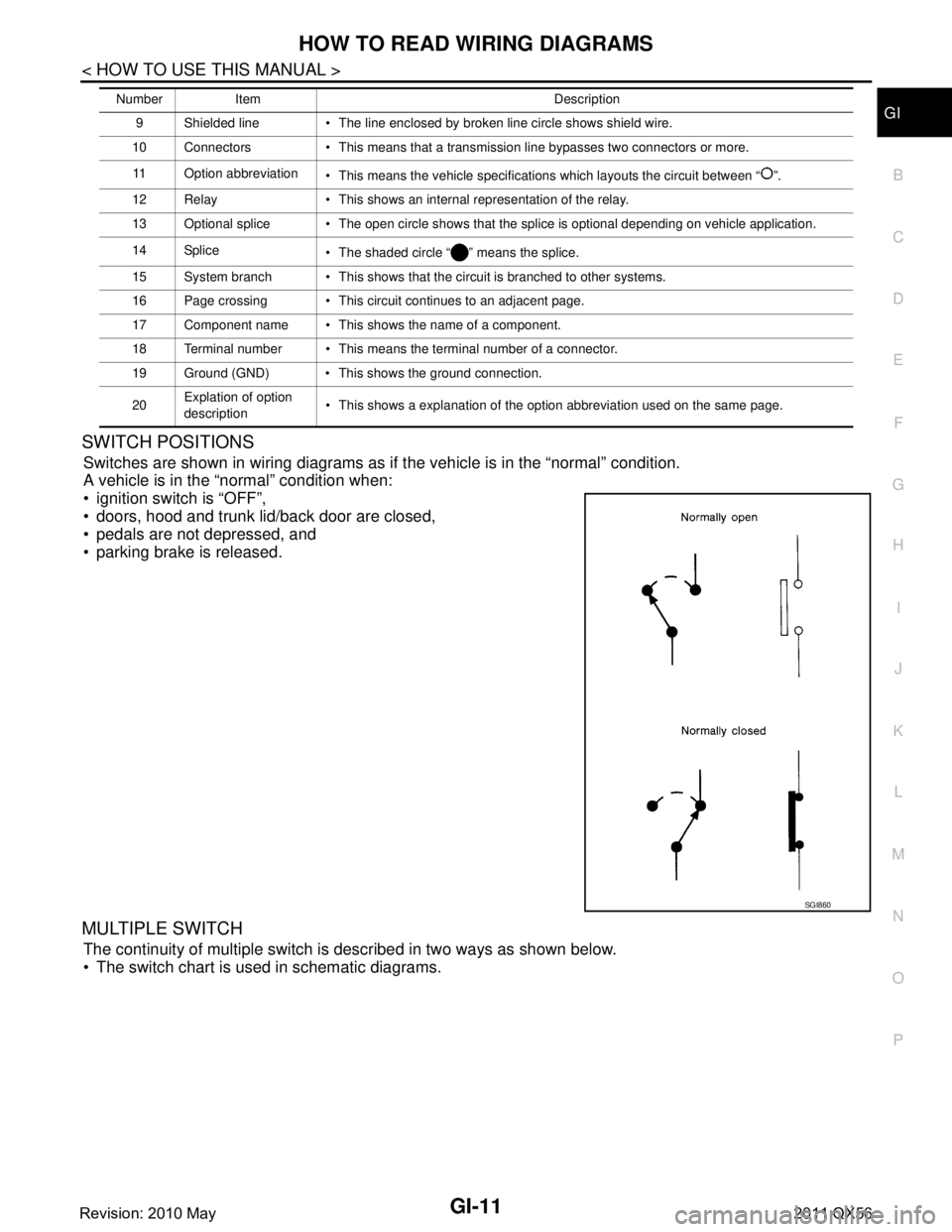
SWITCH POSITIONS
Switches are shown in wiring diagrams as if the vehicle is in the “normal” condition.
A vehicle is in the “normal” condition when:
ignition switch is “OFF”,
doors, hood and trunk lid/back door are closed,
pedals are not depressed, and
parking brake is released.
MULTIPLE SWITCH
The continuity of multiple switch is described in two ways as shown below.
The switch chart is used in schematic diagrams.
9 Shielded line The line enclosed by broken line circle shows shield wire.
10 Connectors This means that a transmission line bypasses two connectors or more.
11 Option abbreviation This means the vehicle specifications which layouts the circuit between “ ”.
12 Relay This shows an internal representation of the relay.
13 Optional splice The open circle shows that the splice is optional depending on vehicle application.
14 Splice The shaded circle “ ” means the splice.
15 System branch This shows that the circuit is branched to other systems.
16 Page crossing This circuit continues to an adjacent page.
17 Component name This shows the name of a component.
18 Terminal number This means the terminal number of a connector.
19 Ground (GND) This shows the ground connection.
20 Explation of option
description This shows a explanation of the option abbreviation used on the same page.
Number Item Description
SGI860
Revision: 2010 May2011 QX56
Page 3081 of 5598

PERFORMANCE TESTHA-25
< BASIC INSPECTION >
C
DE
F
G H
J
K L
M A
B
HA
N
O P
PERFORMANCE TEST
InspectionINFOID:0000000006276158
INSPECTION PROCEDURE
1. Connect recovery/recycling/recharging equipment (for HFC-134a) or manifold gauge.
2. Start the engine, and set to the following condition.
Test condition
3. Maintain test condition until A/C system becomes stable. (Approximately 10 minutes)
4. Check that test results of “recirculating-to-disc harge air temperature” and “ambient air temperature-to-
operating pressure” are within the specified value.
5. When test results are within the specified value, inspection is complete. If any of test result is out of the specified value, perform diagnosis by gauge pressure. Refer to HA-27,
"Symptom Table".
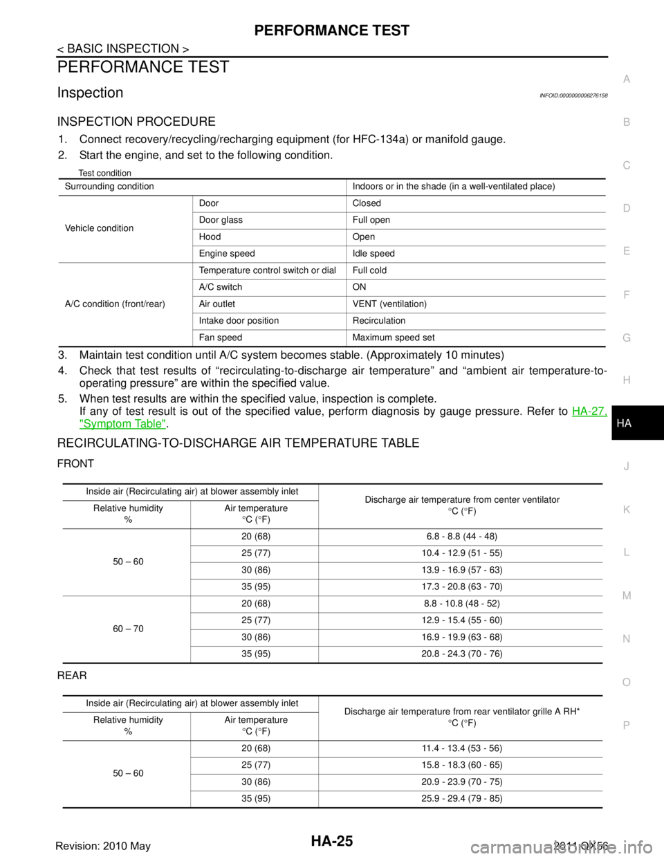
RECIRCULATING-TO-DISCHARGE AIR TEMPERATURE TABLE
FRONT
REAR
Surrounding condition Indoors or in the shade (in a well-ventilated place)
Vehicle conditionDoor Closed
Door glass Full open
Hood Open
Engine speed Idle speed
A/C condition (front/rear) Temperature control switch or dial Full cold
A/C switch ON
Air outlet VENT (ventilation)
Intake door position Recirculation
Fan speed Maximum speed set
Inside air (Recirculating air) at blower assembly inlet
Discharge air temperature from center ventilator
°C ( °F)
Relative humidity
% Air temperature
°C ( °F)
50 – 60 20 (68) 6.8 - 8.8 (44 - 48)
25 (77) 10.4 -
12.9 (51 - 55)
30 (86) 13.9 - 16.9 (57 - 63)
35 (95) 17.3 - 20.8 (63 - 70)
60 – 70 20 (68) 8.8 - 10.8 (48 - 52)
25 (77) 12.9 -
15.4 (55 - 60)
30 (86) 16.9 - 19.9 (63 - 68)
35 (95) 20.8 - 24.3 (70 - 76)
Inside air (Recirculating air) at blower assembly inlet
Discharge air temperature from rear ventilator grille A RH*
°C ( °F)
Relative humidity
% Air temperature
°C ( °F)
50 – 60 20 (68) 11.4 -
13.4 (53 - 56)
25 (77) 15.8 - 18.3 (60 - 65)
30 (86) 20.9 - 23.9 (70 - 75)
35 (95) 25.9 - 29.4 (79 - 85)
Revision: 2010 May2011 QX56
Page 3674 of 5598

MA-4
< PERIODIC MAINTENANCE >
GENERAL MAINTENANCE
PERIODIC MAINTENANCE
GENERAL MAINTENANCE
Explanation of General MaintenanceINFOID:0000000006287728
General maintenance includes those items which shoul d be checked during the normal day-to-day operation
of the vehicle. They are essential if the vehicle is to continue operating properly. The owners can perform
checks and inspections themselves or have their INFINITI dealers do them.
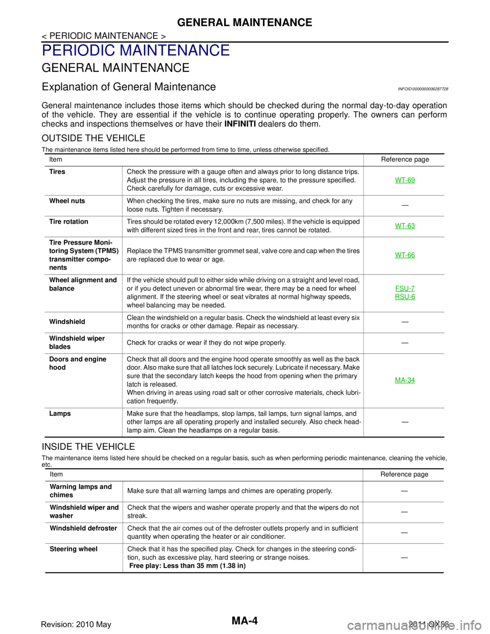
OUTSIDE THE VEHICLE
The maintenance items listed here should be performed fr om time to time, unless otherwise specified.
INSIDE THE VEHICLE
The maintenance items listed here should be checked on a regular basis, such as when performing periodic maintenance, cleaning the vehicle,
etc.
Item Reference page
Tires Check the pressure with a gauge often and always prior to long distance trips.
Adjust the pressure in all tires, including the spare, to the pressure specified.
Check carefully for damage, cuts or excessive wear. WT-69
Wheel nuts
When checking the tires, make sure no nuts are missing, and check for any
loose nuts. Tighten if necessary. —
Tire rotation Tires should be rotated every 12,000km (7,500 miles). If the vehicle is equipped
with different sized tires in the front and rear, tires cannot be rotated. WT-63
Tire Pressure Moni-
toring System (TPMS)
transmitter compo-
nentsReplace the TPMS transmitter grommet seal, valve core and cap when the tires
are replaced due to wear or age.
WT-66
Wheel alignment and
balanceIf the vehicle should pull to either side while driving on a straight and level road,
or if you detect uneven or abnormal tire wear, there may be a need for wheel
alignment. If the steering wheel or seat vibrates at normal highway speeds,
wheel balancing may be needed. FSU-7
RSU-6
Windshield
Clean the windshield on a regular basis. Check the windshield at least every six
months for cracks or other damage. Repair as necessary. —
Windshield wiper
blades Check for cracks or wear if they do not wipe properly. —
Doors and engine
hood Check that all doors and the engine hood operate smoothly as well as the back
door. Also make sure that all latches lock securely. Lubricate if necessary. Make
sure that the secondary latch keeps the hood from opening when the primary
latch is released.
When driving in areas using road salt or other corrosive materials, check lubri-
cation frequently. MA-34
Lamps
Make sure that the headlamps, stop lamps, tail lamps, turn signal lamps, and
other lamps are all operating properly and installed securely. Also check head-
lamp aim. Clean the headlamps on a regular basis. —
Item
Reference page
Warning lamps and
chimes Make sure that all warning lamps and chimes are operating properly. —
Windshield wiper and
washer Check that the wipers and washer operate properly and that the wipers do not
streak.
—
Windshield defroster Check that the air comes out of the defroster outlets properly and in sufficient
quantity when operating the heater or air conditioner. —
Steering wheel Check that it has the specified play. Check for changes in the steering condi-
tion, such as excessive play, hard steering or strange noises.
Free play: Less than 35 mm (1.38 in) —
Revision: 2010 May2011 QX56
Page 3851 of 5598
![INFINITI QX56 2011 Factory Service Manual
PCS-10
< SYSTEM DESCRIPTION >[IPDM E/R]
DIAGNOSIS SYSTEM (IPDM E/R)
DIAGNOSIS SYSTEM (IPDM E/R)
Diagnosis DescriptionINFOID:0000000006220170
AUTO ACTIVE TEST
Description
In auto active test, the IPDM INFINITI QX56 2011 Factory Service Manual
PCS-10
< SYSTEM DESCRIPTION >[IPDM E/R]
DIAGNOSIS SYSTEM (IPDM E/R)
DIAGNOSIS SYSTEM (IPDM E/R)
Diagnosis DescriptionINFOID:0000000006220170
AUTO ACTIVE TEST
Description
In auto active test, the IPDM](/manual-img/42/57033/w960_57033-3850.png)
PCS-10
< SYSTEM DESCRIPTION >[IPDM E/R]
DIAGNOSIS SYSTEM (IPDM E/R)
DIAGNOSIS SYSTEM (IPDM E/R)
Diagnosis DescriptionINFOID:0000000006220170
AUTO ACTIVE TEST
Description
In auto active test, the IPDM E/R sends a drive si
gnal to the following systems to check their operation.
Oil pressure warning lamp
Rear window defogger
Front wiper (LO, HI)
Parking lamp
License plate lamp
Tail lamp
Side marker lamp
Front fog lamp
Headlamp (LO, HI)
A/C compressor (magnet clutch)
Operation Procedure
CAUTION:
Never perform auto active test in the following conditions.
Engine is running.
CONSULT-III is connected.
1. Close the hood and lift the wiper arms from the windshield. (Prevent windshield damage due to wiper
operation)
NOTE:
When auto active test is performed with hood opened, sprinkle water on windshield beforehand.
2. Turn the ignition switch OFF.
3. Turn the ignition switch ON, and within 20 seconds, pr ess the driver door switch 10 times. Then turn the
ignition switch OFF.
CAUTION:
Close passenger door.
4. Turn the ignition switch ON within 10 seconds. Af ter that the horn sounds once and the auto active test
starts.
CAUTION:
Engine starts when igniti on switch is turned ON while brake pedal is depressed.
5. The oil pressure warning lamp starts blinking when the auto active test starts.
6. After a series of the following operations is repeated 3 times, auto active test is completed.
NOTE:
When auto active test has to be cancelled halfway through test, turn the ignition switch OFF.
When auto active test is not activated, door swit ch may be the cause. Check door switch. Refer to DLK-117,
"ComponentFunctionCheck".
Inspection in Auto Active Test
When auto active test is actuated, the following operation sequence is repeated 3 times.
Operation
sequence Inspection location Operation
1 Oil pressure warning lamp Blinks continuously during operation of auto active test
2 Rear window defogger 10 seconds
3 Front wiper LO for 5 seconds → HI for 5 seconds
4 Parking lamp
License plate lamp
Tail lamp
Side marker lamp
Front fog lamp 10 seconds
Revision: 2010 May2011 QX56
Page 3854 of 5598
![INFINITI QX56 2011 Factory Service Manual
PCS
DIAGNOSIS SYSTEM (IPDM E/R)PCS-13
< SYSTEM DESCRIPTION > [IPDM E/R]
C
D
E
F
G H
I
J
K L
B A
O P
N
ACTIVE TEST
Te s t i t e m
PUSH SW
[Off/On]
Displays the status of the push-button ignition swit INFINITI QX56 2011 Factory Service Manual
PCS
DIAGNOSIS SYSTEM (IPDM E/R)PCS-13
< SYSTEM DESCRIPTION > [IPDM E/R]
C
D
E
F
G H
I
J
K L
B A
O P
N
ACTIVE TEST
Te s t i t e m
PUSH SW
[Off/On]
Displays the status of the push-button ignition swit](/manual-img/42/57033/w960_57033-3853.png)
PCS
DIAGNOSIS SYSTEM (IPDM E/R)PCS-13
< SYSTEM DESCRIPTION > [IPDM E/R]
C
D
E
F
G H
I
J
K L
B A
O P
N
ACTIVE TEST
Te s t i t e m
PUSH SW
[Off/On]
Displays the status of the push-button ignition switch judged by IPDM E/R.
INTER/NP SW
[Off/On] Displays the status of the shift position judged by IPDM E/R.
ST RLY CONT
[Off/On] Displays the status of the starter relay status signal received from BCM via CAN
communication.
IHBT RLY -REQ
[Off/On] Displays the status of the starter control relay signal received from BCM via CAN
communication.
ST/INHI RLY
[Off/ ST ON/INHI ON/UNKWN] Displays the status of the starter relay and starter control relay judged by IPDM
E/R.
DETENT SW
[Off/On] Displays the status of the A/T shift selector (detention switch) judged by IPDM E/
R.
S/L RLY -REQ
[Off/On] Displays the status of the steering lock relay signal received from BCM via CAN
communication.
S/L STATE
[LOCK/UNLK/UNKWN] Displays the status of the steering lock judged by IPDM E/R.
OIL P SW
[Open/Close] Displays the status of the oil pressure switch judged by IPDM E/R.
HOOD SW
[Off/On] Displays the status of the hood switch judged by IPDM E/R.
HL WASHER REQ
[Off/On] Displays the status of the headlamp washer request signal received from BCM via
CAN communication.
THFT HRN REQ
[Off/On] Displays the status of the theft warning horn request signal received from BCM
via CAN communication.
HORN CHIRP
[Off/On] Displays the status of the horn reminder signal received from BCM via CAN com-
munication.
Monitor Item
[Unit] MAIN SIG-
NALS Description
Test item Operation Description
CORNERING LAMP LH
NOTE:
This item is indicated, but cannot be tested.
RH
HORN On Operates horn relay for 20 ms.
REAR DEFOGGER Off OFF
On Operates the rear window defogger relay.
FRONT WIPER Off OFF
Lo Operates the front wiper relay.
Hi Operates the front wiper relay and front wiper high relay.
MOTOR FAN* 1OFF
2 Transmits 50% pulse duty signal (PWM signal) to the cooling fan control module.
3 Transmits 75% pulse duty signal (PWM signal) to the cooling fan control module.
4
Transmits 100% pulse duty signal (PWM signal) to the cooling fan control mod-
ule.
HEAD LAMP WASHER On Operates the headlamp washer relay for 1 second.
Revision: 2010 May2011 QX56
Page 3857 of 5598
![INFINITI QX56 2011 Factory Service Manual
PCS-16
< ECU DIAGNOSIS INFORMATION >[IPDM E/R]
IPDM E/R
ST/INHI RLYIgnition switch ON Off
At engine cranking INHI ON
→ ST ON
The status of starter relay or starter control relay cannot be recogniz INFINITI QX56 2011 Factory Service Manual
PCS-16
< ECU DIAGNOSIS INFORMATION >[IPDM E/R]
IPDM E/R
ST/INHI RLYIgnition switch ON Off
At engine cranking INHI ON
→ ST ON
The status of starter relay or starter control relay cannot be recogniz](/manual-img/42/57033/w960_57033-3856.png)
PCS-16
< ECU DIAGNOSIS INFORMATION >[IPDM E/R]
IPDM E/R
ST/INHI RLYIgnition switch ON Off
At engine cranking INHI ON
→ ST ON
The status of starter relay or starter control relay cannot be recognized by
the battery voltage malfunction, etc. when the starter relay is ON and the
starter control relay is OFF. UNKWN
DETENT SW Ignition switch ON Pull the selector lever with selec-
tor lever in P position.
Selector lever in any position oth-
er than P. Off
Release the selector lever with selector lever in P position. On
S/L RLY -REQ None of the conditions below are present. Off
Open the driver door after the ignition switch is turned OFF (for a few
seconds).
Press the push-button ignition switch when the steering lock is activat-
ed. On
S/L STATE Steering lock is locked. LOCK
Steering lock is unlocked. UNLK
[DTC: B210A] is detected. UNKWN
OIL P SW Ignition switch OFF or ACC
Open
Ignition switch ON (engine running)
Ignition switch ON (engine stopped) Close
HOOD SW Close the hood Off
Open the hood On
HL WASHER REQ Not operating Off
Headlamp washer operating On
THFT HRN REQ Not operation Off
Panic alarm is activated
Theft warning alarm is activated
On
HORN CHIRP Not operation Off
Door locking with Intelligent Key (horn chirp mode) On
Monitor Item Condition Value/Status
Revision: 2010 May2011 QX56
Page 3859 of 5598
![INFINITI QX56 2011 Factory Service Manual
PCS-18
< ECU DIAGNOSIS INFORMATION >[IPDM E/R]
IPDM E/R
17
(B) Ground Cooling fan motor
ground
Output Ignition switch ON 0 V
18
(B) Ground Ground — Ignition switch ON 0 V
19
(V) Ground Front fog l INFINITI QX56 2011 Factory Service Manual
PCS-18
< ECU DIAGNOSIS INFORMATION >[IPDM E/R]
IPDM E/R
17
(B) Ground Cooling fan motor
ground
Output Ignition switch ON 0 V
18
(B) Ground Ground — Ignition switch ON 0 V
19
(V) Ground Front fog l](/manual-img/42/57033/w960_57033-3858.png)
PCS-18
< ECU DIAGNOSIS INFORMATION >[IPDM E/R]
IPDM E/R
17
(B) Ground Cooling fan motor
ground
Output Ignition switch ON 0 V
18
(B) Ground Ground — Ignition switch ON 0 V
19
(V) Ground Front fog lamp (RH) Output Lighting
switch 2ND or
AUTO (Light
is illuminated)Front fog lamp switch
OFF
0 V
Front fog lamp switch ON Battery voltage
20
(W) Ground Front fog lamp (LH) Output Lighting
switch 2ND or
AUTO (Light
is illuminated)Front fog lamp switch
OFF
0 V
Front fog lamp switch ON Battery voltage
21
(L) Ground
Headlamp washer re-
lay control Output
Ignition switch
ON Headlamp washer acti-
vated
0 V
Headlamp washer deacti-
vated 12 V
23
(GR/R) Ground Cranking request Output Select lever P or N (Ignition switch ON) 0 V
Select lever in any position other than P or
N (Ignition switch ON)
12 V
Engine running 12 V
24
(W/G) Ground Oil pressure switch Input Ignition switch
ONEngine stopped 0 V
Engine running 12 V
25
(L/Y) Ground Front wiper stop posi-
tion InputIgnition switch
ON Front wiper stop position 0 V
Any position other than
front wiper stop position
12 V
26
(P) Ground CAN-L Input/
Output ——
27
(L) Ground CAN-H
Input/
Output ——
30
(R/W) Ground Starter relay control Output Ignition switch OFF or ACC
At engine cranking
0 V
Ignition switch ON
Engine running 12 V
31
(B) Ground Injector relay control Output Approximately 1 second after turning
the ignition switch ON
Engine running 0 - 1.5 V
Approximately 1 second or more after turn-
ing the ignition switch ON Battery voltage
32
(LG) Ground Hood switch Input Close the hood 12 V
Open the hood 0 V
33
(R) Ground Alternator control Output Ignition switch OFF or ACC 0 V
Ignition switch ON 6 V
34
(P/B) Ground Horn relay control Output The horn is deactivated Battery voltage
The horn is activated 0 V
Te r m i n a l N O .
(Wire color) Description
Condition Va l u e
(Approx.)
Signal name Input/
Output
+–
Revision: 2010 May2011 QX56