Page 2978 of 5598

GI-14
< HOW TO USE THIS MANUAL >
ABBREVIATIONS
ABBREVIATIONS
Abbreviation ListINFOID:0000000006280882
The following ABBREVIATIONS are used:
A
B
C
D
ABBREVIATION DESCRIPTION
A/C Air conditioner
A/C Air conditioning
A/F sensor Air fuel ratio sensor A/T Automatic transaxle/transmission
ABS Anti-lock braking system
ACCS Advance climate control system ACL Air cleaner
AP Accelerator pedal
APP Accelerator pedal position ATF Automatic transmission fluid AV Audio visual
AWD All wheel drive
ABBREVIATION DESCRIPTION BARO Barometric pressureBCM Body control module
BLSD Brake limited slip differential BPP Brake pedal positionBSI Blind spot intervention
BSW Blind spot warning
ABBREVIATION DESCRIPTION CKP Crankshaft positionCL Closed loop
CMP Camshaft position CPP Clutch pedal positionCTP Closed throttle position
CVT Continuously Variable transaxle/transmission
ABBREVIATION DESCRIPTION D
1Drive range first gear
D
2Drive range second gear
D
3Drive range third gear
D
4Drive range fourth gear
DCA Distance control assist DFI Direct fuel injection system
DLC Data link connector
DTC Diagnostic trouble code
Revision: 2010 May2011 QX56
Page 2982 of 5598
GI-18
< HOW TO USE THIS MANUAL >
ABBREVIATIONS
2
3
4
5
6
7
121st range second gear
1GR First gear
ABBREVIATION DESCRIPTION 2
12nd range first gear
2
22nd range second gear
2GR Second gear
2WD 2-Wheel Drive
ABBREVIATION DESCRIPTION 3GR Third gear
ABBREVIATION DESCRIPTION 4GR Fourth gear
4WAS Four wheel active steer 4WD Four wheel drive
ABBREVIATION DESCRIPTION 5GR Fifth gear
ABBREVIATION DESCRIPTION 6GR Sixth gear
ABBREVIATION DESCRIPTION 7GR Seventh gear
ABBREVIATION DESCRIPTION
Revision: 2010 May2011 QX56
Page 3697 of 5598

CHASSIS MAINTENANCEMA-27
< PERIODIC MAINTENANCE >
C
DE
F
G H
I
J
K L
M B
MA
N
O A
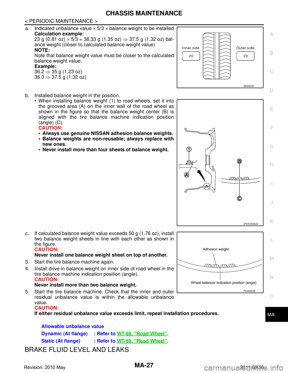
a. Indicated unbalance value
× 5/3 = balance weight to be installed
Calculation example:
23 g (0.81 oz) × 5/3 = 38.33 g (1.35 oz) ⇒ 37.5 g (1.32 oz) bal-
ance weight (closer to calculated balance weight value)
NOTE:
Note that balance weight value must be closer to the calculated
balance weight value.
Example:
36.2 ⇒ 35 g (1.23 oz)
36.3 ⇒ 37.5 g (1.32 oz)
b. Installed balance weight in the position. When installing balance weight (1) to road wheels, set it into
the grooved area (A) on the inner wall of the road wheel as
shown in the figure so that the balance weight center (B) is
aligned with the tire balance machine indication position
(angle) (C).
CAUTION:
Always use genuine NISSAN ad hesion balance weights.
Balance weights are non-re usable; always replace with
new ones.
Never install more than four sheets of balance weight.
c. If calculated balance weight value exceeds 50 g (1.76 oz), install two balance weight sheets in line with each other as shown in
the figure.
CAUTION:
Never install one balance weight sheet on top of another.
3. Start the tire balance machine again.
4. Install drive-in balance weight on inner side of road wheel in the tire balance machine indication position (angle).
CAUTION:
Never install more than two balance weight.
5. Start the tire balance machine. Check that the inner and outer residual unbalance value is within the allowable unbalance
value.
CAUTION:
If either residual unbalan ce value exceeds limit, repeat installation procedures.
BRAKE FLUID LEVEL AND LEAKS
SMA054D
JPEIC0040ZZ
Allowable unbalance value
Dynamic (At flange) : Refer to WT-69, "
Road Wheel".
Static (At flange) : Refer to WT-69, "
Road Wheel".
PEIA0033E
Revision: 2010 May2011 QX56
Page 5513 of 5598

ROAD WHEELWT-63
< PERIODIC MAINTENANCE >
C
DF
G H
I
J
K L
M A
B
WT
N
O P
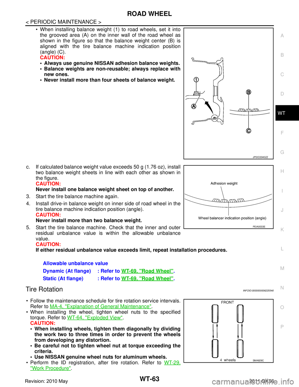
When installing balance weight (1) to road wheels, set it into the grooved area (A) on the inner wall of the road wheel as
shown in the figure so that the balance weight center (B) is
aligned with the tire balance machine indication position
(angle) (C).
CAUTION:
Always use genuine NISSAN ad hesion balance weights.
Balance weights are non-re usable; always replace with
new ones.
Never install more than four sheets of balance weight.
c. If calculated balance weight value exceeds 50 g (1.76 oz), install two balance weight sheets in line with each other as shown in
the figure.
CAUTION:
Never install one balance weight sheet on top of another.
3. Start the tire balance machine again.
4. Install drive-in balance weight on inner side of road wheel in the tire balance machine indication position (angle).
CAUTION:
Never install more than two balance weight.
5. Start the tire balance machine. Check that the inner and outer residual unbalance value is within the allowable unbalance
value.
CAUTION:
If either residual unbalan ce value exceeds limit, repeat installation procedures.
Tire RotationINFOID:0000000006225546
Follow the maintenance schedule for tire rotation service intervals.
Refer to MA-4, "
Explanation of General Maintenance".
When installing the wheel, tighten wheel nuts to the specified torque. Refer to WT-64, "
Exploded View".
CAUTION:
When installing wheels, tighte n them diagonally by dividing
the work two to three times in order to prevent the wheels
from developing any distortion.
Be careful not to tighten wh eel nut at torque exceeding the
criteria.
Use NISSAN genuine wheel nuts for aluminum wheels.
Perform the ID registration, after tire rotation. Refer to WT-29,
"Work Procedure".
JPEIC0040ZZ
Allowable unbalance value
Dynamic (At flange) : Refer to WT-69, "
Road Wheel".
Static (At flange) : Refer to WT-69, "
Road Wheel".
PEIA0033E
SMA829C
Revision: 2010 May2011 QX56