2011 INFINITI QX56 brake fluid
[x] Cancel search: brake fluidPage 485 of 5598

HYDRAULIC BOOSTER ASSEMBLYBR-15
< PERIODIC MAINTENANCE >
C
DE
G H
I
J
K L
M A
B
BR
N
O P
HYDRAULIC BOOSTER ASSEMBLY
InspectionINFOID:0000000006222467
OPERATION CHECK
1. Turn the ignition switch OFF.
2. Depress the brake pedal 20 times or more. NOTE:
The pressure loss in the accumulator results in a large brake pedal stroke. In addition to this, the brake
pedal depression becomes lighter in initial stage.
3. Check that the fluid level in the reservoir tank is MAX line.
4. Position the selector lever in P range to release the parking brake.
5. Turn the ignition switch ON to check the time between motor activation and motor stop.
6. After the motor is stopped, check that the ABS warning lamp and the VDC warning lamp in the combina- tion meter are OFF when the engine is started.
7. Stop the engine (ignition switch OFF).
8. Turn the ignition switch ON and depress the brake pedal 4 to 5 times to check the time between motor activation and motor stop.
9. Turn the ignition switch OFF. Turn the ignition switch ON again. Check that the VDC warning lamp turns ON when the brake pedal is depressed 15 to 20 times.
10. Check that the VDC warning lamp turns ON when the brake pedal is depressed 15 to 20 times after the lapse of 120 seconds or more after the ignition switch is turned ON again.
11. Perform the self-diagnosis for “ABS” with CONSULT-III and erase self-diagnosis results.
FUNCTION CHECK
1. Turn the ignition switch OFF.
2. Depress the brake pedal 20 times or more.
NOTE:
The pressure loss in the accumulator results in a large brake pedal stroke. In addition to this, the brake
pedal depression becomes lighter in initial stage.
3. Turn the ignition switch ON with the brake pedal depr essed to check that the clearance between the brake
pedal and the dash lower panel decreases. Motor operating time : 18 seconds or less
Motor operating time : 2
− 11 seconds
Revision: 2010 May2011 QX56
Page 493 of 5598

BRAKE PIPINGBR-23
< REMOVAL AND INSTALLATION >
C
DE
G H
I
J
K L
M A
B
BR
N
O P
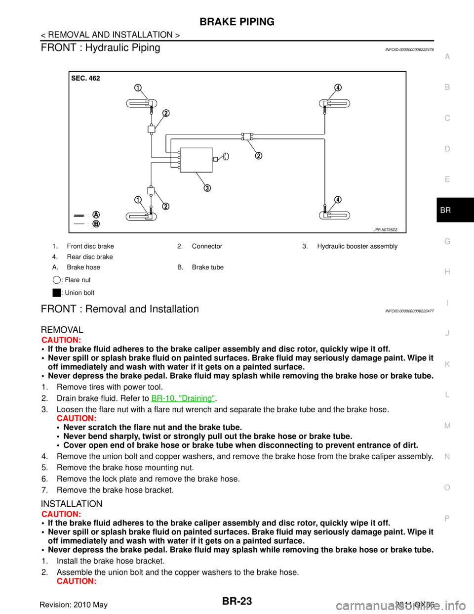
FRONT : Hydraulic PipingINFOID:0000000006222476
FRONT : Removal and InstallationINFOID:0000000006222477
REMOVAL
CAUTION:
If the brake fluid adheres to the brake caliper assembly and disc rotor, quickly wipe it off.
Never spill or splash brake fluid on painted surfaces. Brake fluid may seriously damage paint. Wipe it
off immediately and wash with wate r if it gets on a painted surface.
Never depress the brake pedal. Brake fluid may spl ash while removing the brake hose or brake tube.
1. Remove tires with power tool.
2. Drain brake fluid. Refer to BR-10, "
Draining".
3. Loosen the flare nut with a flare nut wrench and separate the brake tube and the brake hose.
CAUTION:
Never scratch the flare nut and the brake tube.
Never bend sharply, twist or strongly pull out the brake hose or brake tube.
Cover open end of brake hose or brake tube wh en disconnecting to prevent entrance of dirt.
4. Remove the union bolt and copper washers, and remove the brake hose from the brake caliper assembly.
5. Remove the brake hose mounting nut.
6. Remove the lock plate and remove the brake hose.
7. Remove the brake hose bracket.
INSTALLATION
CAUTION:
If the brake fluid adheres to the brake caliper assembly and disc rotor, quickly wipe it off.
Never spill or splash brake fluid on painted surfaces. Brake fluid may seriously damage paint. Wipe it
off immediately and wash with wate r if it gets on a painted surface.
Never depress the brake pedal. Brake fluid may spl ash while removing the brake hose or brake tube.
1. Install the brake hose bracket.
2. Assemble the union bolt and the copper washers to the brake hose. CAUTION:
1. Front disc brake 2. Connector 3. Hydraulic booster assembly
4. Rear disc brake
A. Brake hose B. Brake tube
: Flare nut
: Union bolt
JPFIA0726ZZ
Revision: 2010 May2011 QX56
Page 494 of 5598

BR-24
< REMOVAL AND INSTALLATION >
BRAKE PIPING
Never reuse the copper washer.
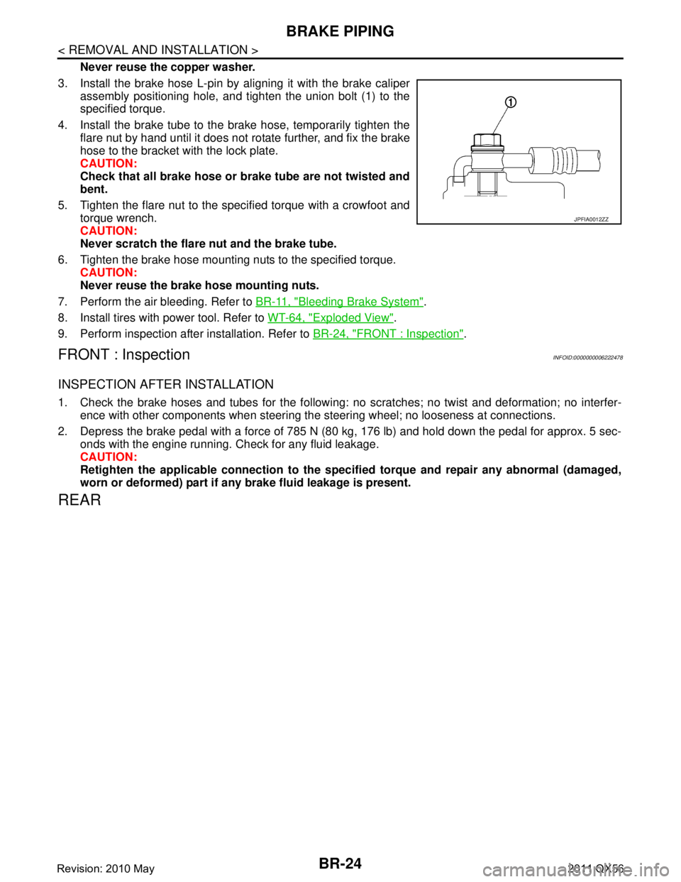
3. Install the brake hose L-pin by aligning it with the brake caliper assembly positioning hole, and tighten the union bolt (1) to the
specified torque.
4. Install the brake tube to the brake hose, temporarily tighten the flare nut by hand until it does not rotate further, and fix the brake
hose to the bracket with the lock plate.
CAUTION:
Check that all brake hose or brake tube are not twisted and
bent.
5. Tighten the flare nut to the specified torque with a crowfoot and torque wrench.
CAUTION:
Never scratch the flare nut and the brake tube.
6. Tighten the brake hose mounting nuts to the specified torque. CAUTION:
Never reuse the brake hose mounting nuts.
7. Perform the air bleeding. Refer to BR-11, "
Bleeding Brake System".
8. Install tires with power tool. Refer to WT-64, "
Exploded View".
9. Perform inspection after installation. Refer to BR-24, "
FRONT : Inspection".
FRONT : InspectionINFOID:0000000006222478
INSPECTION AFTER INSTALLATION
1. Check the brake hoses and tubes for the following: no scratches; no twist and deformation; no interfer-
ence with other components when steering the steering wheel; no looseness at connections.
2. Depress the brake pedal with a force of 785 N (80 kg, 176 lb) and hold down the pedal for approx. 5 sec- onds with the engine running. Check for any fluid leakage.
CAUTION:
Retighten the applicable connection to the specified torque and repair any abnormal (damaged,
worn or deformed) part if any brake fluid leakage is present.
REAR
JPFIA0012ZZ
Revision: 2010 May2011 QX56
Page 496 of 5598

BR-26
< REMOVAL AND INSTALLATION >
BRAKE PIPING
REAR : Removal and Installation
INFOID:0000000006222481
REMOVAL
CAUTION:
If the brake fluid adheres to the brake caliper assembly and disc rotor, quickly wipe it off.
Never spill or splash brake fluid on painted surfaces. Brake fluid may seriously damage paint. Wipe it
off immediately and wash with wate r if it gets on a painted surface.
Never depress the brake pedal. Brake fluid may spl ash while removing the brake hose or brake tube.
1. Remove tires with power tool.
2. Drain brake fluid. Refer to BR-10, "
Draining".
3. Loosen the flare nut with a flare nut wrench and separate the brake tube and the brake hose. CAUTION:
Never scratch the flare nut and the brake tube.
Never bend sharply, twist or strongly pull out the brake hose or brake tube.
Cover open end of brake hose or brake tube wh en disconnecting to prevent entrance of dirt.
4. Remove the union bolt and copper washers, and remove the brake hose from the brake caliper assembly.
5. Remove the lock plate and remove the brake hose.
INSTALLATION
CAUTION:
If the brake fluid adheres to the brake caliper assembly and disc rotor, quickly wipe it off.
Never spill or splash brake fluid on painted surfaces. Brake fluid may seriously damage paint. Wipe it
off immediately and wash with wate r if it gets on a painted surface.
Never depress the brake pedal. Brake fluid may spl ash while removing the brake hose or brake tube.
1. Assemble the union bolt and the copper washers to the brake hose. CAUTION:
Never reuse the copper washer.
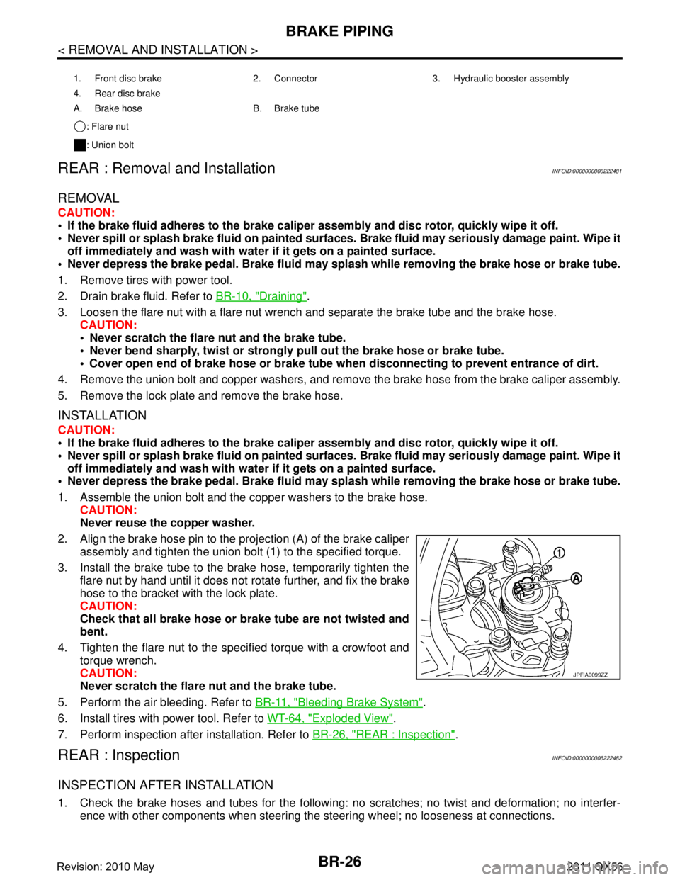
2. Align the brake hose pin to the projection (A) of the brake caliper
assembly and tighten the union bolt (1) to the specified torque.
3. Install the brake tube to the brake hose, temporarily tighten the flare nut by hand until it does not rotate further, and fix the brake
hose to the bracket with the lock plate.
CAUTION:
Check that all brake hose or brake tube are not twisted and
bent.
4. Tighten the flare nut to the specified torque with a crowfoot and torque wrench.
CAUTION:
Never scratch the flare nut and the brake tube.
5. Perform the air bleeding. Refer to BR-11, "
Bleeding Brake System".
6. Install tires with power tool. Refer to WT-64, "
Exploded View".
7. Perform inspection after installation. Refer to BR-26, "
REAR : Inspection".
REAR : InspectionINFOID:0000000006222482
INSPECTION AFTER INSTALLATION
1. Check the brake hoses and tubes for the following: no scratches; no twist and deformation; no interfer-
ence with other components when steering the steering wheel; no looseness at connections.
1. Front disc brake 2. Connector 3. Hydraulic booster assembly
4. Rear disc brake
A. Brake hose B. Brake tube
: Flare nut
: Union bolt
JPFIA0099ZZ
Revision: 2010 May2011 QX56
Page 497 of 5598

BRAKE PIPINGBR-27
< REMOVAL AND INSTALLATION >
C
DE
G H
I
J
K L
M A
B
BR
N
O P
2. Depress the brake pedal with a force of 785 N (80 kg, 176 lb) and hold down the pedal for approx. 5 sec- onds with the engine running. Check for any fluid leakage.
CAUTION:
Retighten the applicable connect ion to the specified torque and repair any abnormal (damaged,
worn or deformed) part if any brake fluid leakage is present.
Revision: 2010 May2011 QX56
Page 499 of 5598

HYDRAULIC BOOSTER ASSEMBLYBR-29
< REMOVAL AND INSTALLATION >
C
DE
G H
I
J
K L
M A
B
BR
N
O P
Removal and InstallationINFOID:0000000006222484
REMOVAL
1. Turn the ignition switch OFF. CAUTION:
Never turn the ignition switch ON before th e completion of the installation procedure.
2. Drain brake fluid. Refer to BR-10, "
Draining".
3. Depress the brake pedal 20 times or more to release the pressure from the accumulator. CAUTION:
Always perform this step before re moving the hydraulic booster assembly.
4. Disconnect hydraulic booster assembly harness connector.
5. Separate the brake tube from hydraulic booste r assembly with a flare nut wrench. Refer to BR-22,
"FRONT : Exploded View".
6. Remove brake tube from clip.
1. Reservoir cap 2. Lab el 3. Reservoir tank
4. Pin 5. Motor/accumulator assembly 6. Brake tube
7. Brake hose assembly 8. Grommet 9. Harness band
10. Collar 11. Bushing 12. Pin mount
13. Grommet 14. Bracket 15. Cap
16. Bushing 17. Bracket 18. ABS actuator and electric unit (con- trol unit)
19. Gasket 20. Spacer
: Apply brake fluid.
Refer to GI-4, "
Components" for symbols not described on the above.
JPFIA0748GB
Revision: 2010 May2011 QX56
Page 501 of 5598

HYDRAULIC BOOSTER ASSEMBLYBR-31
< REMOVAL AND INSTALLATION >
C
DE
G H
I
J
K L
M A
B
BR
N
O P
2. Remove the reservoir tank mounting pin with a pin punch (com- mercial service tool).
3. Remove bolt and remove the reservoir tank and grommets from the ABS actuator and electric unit (control unit).
CAUTION:
Never drop the removed parts. The parts must not be
reused if they are dropped.
4. Slide the clamp and remove brake hose assembly.
5. Remove the brake tube with a flare nut wrench. CAUTION:
Never scratch the flare nut and the brake tube.
6. Remove the cap with a suitable tool (A).
7. Remove grommets and screws ( ) and remove motor/accumu- lator assembly harness.
8. Cut harness band. CAUTION:
Never damage the harness.
9. Remove motor/accumulator assembly from ABS actuator and electric unit (control unit).
10. Remove bushings and collars from motor/accumulator assem- bly.
11. Remove brackets and bushing fr om ABS actuator and electric
unit (control unit).
12. Remove pin mount.
13. After replacing motor/accumulator assembly, always follow the accumulator disposal procedure to discard the motor/accumulator assembly. Refer to BR-33, "
Disposal".
ASSEMBLY
Note the following, and assembly in the reverse order of disassembly.
Never use mineral oils such as kerosene or gasoline and rubber grease during the cleaning and assembly
process.
Never drop the removed parts when installing. The parts must not be reused if they are dropped.
Never allow foreign matter (e.g. dust) and oils ot her than brake fluid to enter the reservoir tank.
For non reusable parts, refer to BR-28, "
Exploded View".
When connecting motor/accumulator assembly harness, check the order of harness colors.
Temporarily tighten the brake tube flare nut to the motor/accumula- tor assembly and ABS actuator and electric unit (control unit) by
hand. Then tighten it to the specified torque with a crowfoot and
torque wrench.
CAUTION:
Never scratch the flare nut and the brake tube.
JPFIA0750ZZ
JPFIA0752ZZ
JPFIA0751ZZ
A: Black
B: Red
JPFIA0753ZZ
Revision: 2010 May2011 QX56
Page 502 of 5598

BR-32
< REMOVAL AND INSTALLATION >
HYDRAULIC BOOSTER ASSEMBLY
Apply new brake fluid to grommet of between reservoir tank and grommet and ABS actuator and electric unit
(control unit).
Inspection and AdjustmentINFOID:0000000006222486
ADJUSTMENT BEFORE INSTALLATION
Input Rod Length adjustment
1. Loosen the lock nut (1) and adjust the input rod (2) to the speci-
fied length (A).
2. Tighten the lock nut to the specified torque.
INSPECTION AFTER INSTALLATION
Operation Check
1. Turn the ignition switch OFF.
2. Depress the brake pedal 20 times or more. NOTE:
The pressure loss in the accumulator results in a large brake pedal stroke. In addition to this, the brake
pedal depression becomes lighter in initial stage.
3. Check that the fluid level in the reservoir tank is MAX line.
4. Position the selector lever in P range to release the parking brake.
5. Turn the ignition switch ON to check the time between motor activation and motor stop.
6. After the motor is stopped, check that the ABS warn ing lamp and the VDC warning lamp in the combina-
tion meter are OFF when the engine is started.
7. Stop the engine (ignition switch OFF).
8. Turn the ignition switch ON and depress the brake pedal 4 to 5 times to check the time between motor activation and motor stop.
9. Turn the ignition switch OFF. Turn the ignition swit ch ON again. Check that the VDC warning lamp turns
ON when the brake pedal is depressed 15 to 20 times.
10. Check that the VDC warning lamp turns ON when the brake pedal is depressed 15 to 20 times after the lapse of 120 seconds or more after the ignition switch is turned ON again.
11. Perform the self-diagnosis for “ABS” with CONSULT- III and erase all the stored self-diagnosis results.
Function Check
1. Turn the ignition switch OFF.
2. Depress the brake pedal 20 times or more.
NOTE:
The pressure loss in the accumulator results in a large brake pedal stroke. In addition to this, the brake
pedal depression becomes lighter in initial stage.
3. Turn the ignition switch ON with the brake pedal depr essed to check that the clearance between the brake
pedal and the dash lower panel decreases. A : Refer to
BR-47, "
Brake Booster".
JPFIA0728ZZ
Motor operating time : 18 seconds or less
Motor operating time : 2 − 11 seconds
Revision: 2010 May2011 QX56