2011 INFINITI QX56 air filter
[x] Cancel search: air filterPage 2995 of 5598

PRECAUTIONSGI-31
< PRECAUTION >
C
DE
F
G H
I
J
K L
M B
GI
N
O P
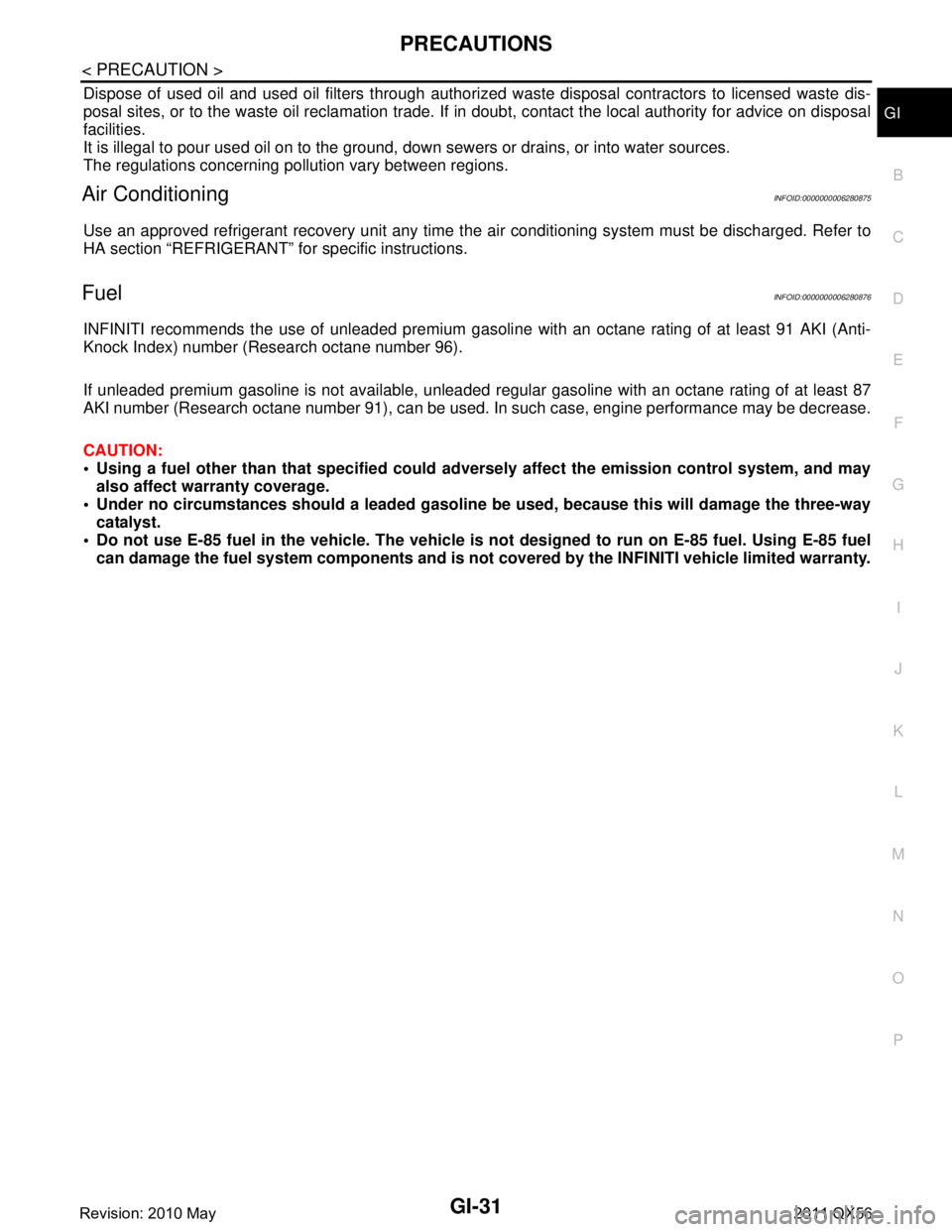
Dispose of used oil and used oil filters through authorized waste disposal contractors to licensed waste dis-
posal sites, or to the waste oil reclamation trade. If in doubt, contact the local authority for advice on disposal
facilities.
It is illegal to pour used oil on to the ground, dow n sewers or drains, or into water sources.
The regulations concerning po llution vary between regions.
Air ConditioningINFOID:0000000006280875
Use an approved refrigerant recovery unit any time t he air conditioning system must be discharged. Refer to
HA section “REFRIGERANT” fo r specific instructions.
FuelINFOID:0000000006280876
INFINITI recommends the use of unleaded premium gasoli ne with an octane rating of at least 91 AKI (Anti-
Knock Index) number (Research octane number 96).
If unleaded premium gasoline is not available, unleaded r egular gasoline with an octane rating of at least 87
AKI number (Research octane number 91), can be used. In such case, engine performance may be decrease.
CAUTION:
Using a fuel other than that specified could ad versely affect the emission control system, and may
also affect warranty coverage.
Under no circumstances should a leaded gasoline be used, because this will damage the three-way
catalyst.
Do not use E-85 fuel in the vehicle . The vehicle is not designed to run on E-85 fuel. Using E-85 fuel
can damage the fuel system components and is not covered by the INFINITI vehicle limited warranty.
Revision: 2010 May2011 QX56
Page 3125 of 5598
![INFINITI QX56 2011 Factory Service Manual
SYSTEMHAC-19
< SYSTEM DESCRIPTION > [AUTOMATIC AIR CONDITIONING]
C
D
E
F
G H
J
K L
M A
B
HAC
N
O P
*: Inlet status is displayed by indi cator when activating automatic control
Without ACCS (Advanced INFINITI QX56 2011 Factory Service Manual
SYSTEMHAC-19
< SYSTEM DESCRIPTION > [AUTOMATIC AIR CONDITIONING]
C
D
E
F
G H
J
K L
M A
B
HAC
N
O P
*: Inlet status is displayed by indi cator when activating automatic control
Without ACCS (Advanced](/manual-img/42/57033/w960_57033-3124.png)
SYSTEMHAC-19
< SYSTEM DESCRIPTION > [AUTOMATIC AIR CONDITIONING]
C
D
E
F
G H
J
K L
M A
B
HAC
N
O P
*: Inlet status is displayed by indi cator when activating automatic control
Without ACCS (Advanced Climate Control System)
1. Intake door 2. In-cabin microfilter 3. Blower motor
4. Evaporator 5. Air mix door (Driver side/Passenger
side)6. Heater core
7. Foot door 8. Ventilator door 9. Upper ventilator door
10. Defroster door Fresh air intake Recirculation air
Center ventilator Side ventilator Upper ventilator
Foot Rear foot Defroster
Switch/Dial position Door position
Ventilator door Foot
doorDefroster
door Intake
door Upper
ventilator
door Air mix
door
(Driver side) Air mix
door
(Passen-
ger
side)
AUTO switch AUTO — AUTO
MODE switch VENT H E N —
B/L I F N —
FOOT J G O — D/F J G O B —
DEF switch J E P B K —
Intake switch
*FRE — B —
REC — A —
Upper ventila- tor switch ON — L – M —
OFF — K —
Temperature control dial
(Driver side) DUAL
switch:
OFF18.0
°C (60 °F) — C
18.5 °C (61 °F) ⇔
31.5 °C (89 °F) —AUTO
32.0 °C (90 °F) — D
Temperature control dial
(Driver side) DUAL
switch:
ON18.0
°C (60 °F) — C —
18.5 °C (61 °F) ⇔
31.5 °C (89 °F) —AUTO—
32.0 °C (90 °F) — D —
Temperature control dial
(Passenger side) 18.0
°C (60 °F) — C
18.5 °C (61 °F) ⇔
31.5 °C (89 °F) —AUTO
32.0 °C (90 °F) — D
OFF switch AUTO —
Revision: 2010 May2011 QX56
Page 3126 of 5598
![INFINITI QX56 2011 Factory Service Manual
HAC-20
< SYSTEM DESCRIPTION >[AUTOMATIC AIR CONDITIONING]
SYSTEM
1. Intake door 2. In-cabin microfilter 3. Blower motor
4. Evaporator 5. Air mix door (Driver side/Passenger
side)6. Heater core
7. Fo INFINITI QX56 2011 Factory Service Manual
HAC-20
< SYSTEM DESCRIPTION >[AUTOMATIC AIR CONDITIONING]
SYSTEM
1. Intake door 2. In-cabin microfilter 3. Blower motor
4. Evaporator 5. Air mix door (Driver side/Passenger
side)6. Heater core
7. Fo](/manual-img/42/57033/w960_57033-3125.png)
HAC-20
< SYSTEM DESCRIPTION >[AUTOMATIC AIR CONDITIONING]
SYSTEM
1. Intake door 2. In-cabin microfilter 3. Blower motor
4. Evaporator 5. Air mix door (Driver side/Passenger
side)6. Heater core
7. Foot door 8. Ventilator door 9. Upper ventilator door
10. Defroster door Fresh air intake Recirculation air
Center ventilator Side ventilator Upper ventilator
Foot Rear foot Defroster
JMIIA0727ZZ
Switch/Dial position Door position
Ventilator door Foot
doorDefroster
door Intake
door Upper
ventilator door Air mix
door
(Driver side) Air mix
door
(Passen- ger
side)
AUTO switch AUTO — AUTO
MODE switch VENT H E N —
B/L I F N —
FOOT J G O — D/F J G O B —
DEF switch J EPBK —
FRE switch
*—B—
REC switch
*—A—
Upper ventila- tor switch ON — L – M —
OFF — K —
Revision: 2010 May2011 QX56
Page 3134 of 5598
![INFINITI QX56 2011 Factory Service Manual
HAC-28
< SYSTEM DESCRIPTION >[AUTOMATIC AIR CONDITIONING]
SYSTEM
ACCS (ADVANCED CLIMATE CONT ROL SYSTEM) : System Diagram
INFOID:0000000006275875
ACCS (ADVANCED CLIMATE CONTROL SYSTEM) : System Desc INFINITI QX56 2011 Factory Service Manual
HAC-28
< SYSTEM DESCRIPTION >[AUTOMATIC AIR CONDITIONING]
SYSTEM
ACCS (ADVANCED CLIMATE CONT ROL SYSTEM) : System Diagram
INFOID:0000000006275875
ACCS (ADVANCED CLIMATE CONTROL SYSTEM) : System Desc](/manual-img/42/57033/w960_57033-3133.png)
HAC-28
< SYSTEM DESCRIPTION >[AUTOMATIC AIR CONDITIONING]
SYSTEM
ACCS (ADVANCED CLIMATE CONT ROL SYSTEM) : System Diagram
INFOID:0000000006275875
ACCS (ADVANCED CLIMATE CONTROL SYSTEM) : System DescriptionINFOID:0000000006275876
ACCS (advanced climate control system) controls pass enger room air. It maintains the cleanliness of the
passenger room air using an in-cabin microfilter and a combination of each of the following functions.
- HAC-28, "
ACCS (ADVANCED CLIMATE CONT ROL SYSTEM) : Automatic Intake Control (Exhaust Gas /
Outside Odor Detecting Mechanism)"
-HAC-29, "ACCS (ADVANCED CLIMATE CONTROL SYSTEM) : Plasmacluster Control"
NOTE:
Plasmacluster
™ ion technology developed by Sharp Corporation is installed in this item.
Plasmacluster
™ is a trademark of Sharp Corporation.
Various operations of ACCS (advanced climate contro l system) are transmitted from preset switch to AV
control unit via communication line and from AV contro l unit to A/C auto amp. via CAN communication. A/C
auto amp. sends each indication information to AV c ontrol unit via CAN communication. AV control unit dis-
plays each indication information that is received.
ACCS (ADVANCED CLIMATE CONTROL SYSTE M) : Automatic Intake Control (Ex-
haust Gas / Outside Odor Detecting Mechanism)
INFOID:0000000006275877
DESCRIPTION
In addition to air inlet automatic control of front automatic air conditioning system, A/C auto amp. controls
automatically air inlet according to signal from ex haust gas / outside odor detecting sensor, so that unpleasant
outside odor does not enter in passenger room.
OPERATION DESCRIPTION
When pressing auto intake switch while front blower motor is operated and DEF switch is OFF, auto intake switch indicator lamp and intake switch indicator lamp turn ON. Air inlet is fixed to recirculation for approxi-
mately 5 minutes, and then is switched to automatic intake control (exhaust gas / outside odor detecting
mechanism).
Air inlet switches to recirculation when exhaust gas or outside odor is detected while automatic intake control
(exhaust gas / outside odor detecting mechanism) is operated. After that, air inlet switches to fresh air intake
when exhaust gas or outside odor becomes not detectable.
NOTE:
JMIIA0819GB
Revision: 2010 May2011 QX56
Page 3660 of 5598

ENGINE OILLU-7
< PERIODIC MAINTENANCE >
C
DE
F
G H
I
J
K L
M A
LU
NP
O
PERIODIC MAINTENANCE
ENGINE OIL
InspectionINFOID:0000000006289616
OIL LEVEL
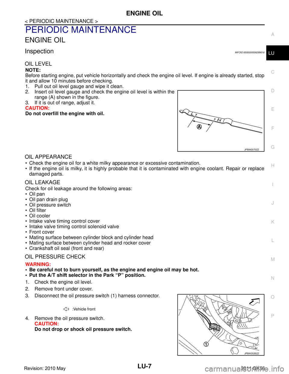
NOTE:
Before starting engine, put vehicle horizontally and check
the engine oil level. If engine is already started, stop
it and allow 10 minutes before checking.
1. Pull out oil level gauge and wipe it clean.
2. Insert oil level gauge and check the engine oil level is within the range (A) shown in the figure.
3. If it is out of range, adjust it.
CAUTION:
Do not overfill the engine with oil.
OIL APPEARANCE
Check the engine oil for a white milky appearance or excessive contamination.
If the engine oil is milky, it is highly probable that it is contaminated with engine coolant. Repair or replace
damaged parts.
OIL LEAKAGE
Check for oil leakage around the following areas:
Oil pan
Oil pan drain plug
Oil pressure switch
Oil filter
Oil cooler
Intake valve timing control cover
Intake valve timing control solenoid valve
Front cover
Mating surface between cylinder block and cylinder head
Mating surface between cylinder head and rocker cover
Crankshaft oil seal (front and rear)
OIL PRESSURE CHECK
WARNING:
• Be careful not to burn yourself, as th e engine and engine oil may be hot.
Put the A/T shift selector in the Park “P” position.
1. Check the engine oil level.
2. Remove front under cover.
3. Disconnect the oil pressure switch (1) harness connector.
4. Remove the oil pressure switch. CAUTION:
Do not drop or shock oil pressure switch.
JPBIA0070ZZ
:Vehicle front
JPBIA3526ZZ
Revision: 2010 May2011 QX56
Page 3665 of 5598

LU-12
< REMOVAL AND INSTALLATION >
OIL COOLER
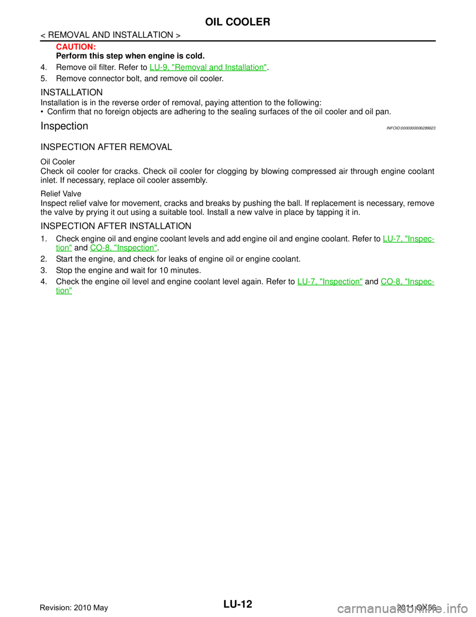
CAUTION:
Perform this step when engine is cold.
4. Remove oil filter. Refer to LU-9, "
Removal and Installation".
5. Remove connector bolt, and remove oil cooler.
INSTALLATION
Installation is in the reverse order of removal, paying attention to the following:
Confirm that no foreign objects are adhering to the sealing surfaces of the oil cooler and oil pan.
InspectionINFOID:0000000006289623
INSPECTION AFTER REMOVAL
Oil Cooler
Check oil cooler for cracks. Check oil cooler for clogging by blowing compressed air through engine coolant
inlet. If necessary, replace oil cooler assembly.
Relief Valve
Inspect relief valve for movement, cracks and breaks by pushing the ball. If replacement is necessary, remove
the valve by prying it out using a suitable tool. Install a new valve in place by tapping it in.
INSPECTION AFTER INSTALLATION
1. Check engine oil and engine coolant levels and add engine oil and engine coolant. Refer to LU-7, "Inspec-
tion" and CO-8, "Inspection".
2. Start the engine, and check for l eaks of engine oil or engine coolant.
3. Stop the engine and wait for 10 minutes.
4. Check the engine oil level and engine coolant level again. Refer to LU-7, "
Inspection" and CO-8, "Inspec-
tion"
Revision: 2010 May2011 QX56
Page 3671 of 5598

MA-1
MAINTENANCE
C
DE
F
G H
I
J
K L
M B
MA
SECTION MA
N
O A
CONTENTS
MAINTENANCE
PREPARATION .............
...............................3
PREPARATION .............................................. .....3
Special Service Tool ........................................... ......3
Commercial Service Tool ..........................................3
PERIODIC MAINTENANCE ..........................4
GENERAL MAINTENANCE ........................... .....4
Explanation of General Maintenance .................. ......4
PERIODIC MAINTENANCE ................................6
Introduction of Periodic Maintenance .................. ......6
Schedule 1 ................................................................6
Schedule 2 ................................................................8
RECOMMENDED FLUIDS AND LUBRI-
CANTS ................................................................
10
Fluids and Lubricants .......................................... ....10
Engine Oil Recommendation ..................................10
Anti-Freeze Coolant Mixture Ratio ..........................11
ENGINE MAINTENANCE ...................................12
DRIVE BELTS ....................................................... ....12
DRIVE BELTS : Exploded View ..............................12
DRIVE BELTS : Checking .......................................12
DRIVE BELTS : Tension Adjustment .....................12
ENGINE COOLANT ............................................... ....12
ENGINE COOLANT : Inspection .............................12
ENGINE COOLANT : Draining ................................13
ENGINE COOLANT : Refilling ................................13
ENGINE COOLANT : Flushing ...............................15
RESERVOIR TANK CAP ..........................................15
RESERVOIR TANK CAP : Inspection ................. ....15
RADIATOR ............................................................ ....16
RADIATOR : Inspection ..........................................16
FUEL LINES .......................................................... ....16
FUEL LINES : Inspection ........................................17
AIR CLEANER FILTER ......................................... ....17
AIR CLEANER FILTER : Removal and Installation
....
17
ENGINE OIL ........................................................... ....17
ENGINE OIL : Draining ............................................17
ENGINE OIL : Refilling ............................................17
OIL FILTER ............................................................ ....18
OIL FILTER : Removal and Installation ...................18
SPARK PLUG ........................................................ ....18
SPARK PLUG : Removal and Installation ...............19
SPARK PLUG : Inspection ......................................19
EVAP VAPOR LINES ............................................ ....20
EVAP VAPOR LINES : Inspection ...........................20
CHASSIS MAINTENANCE ...............................21
EXHAUST SYSTEM . ..................................................21
EXHAUST SYSTEM : Inspec tion ............................21
A/T FLUID .............................................................. ....21
A/T FLUID : Inspection ............................................21
TRANSFER FLUID ................................................ ....21
TRANSFER FLUID : Inspection ..............................21
TRANSFER FLUID : Draining .................................21
TRANSFER FLUID : Refilling ..................................22
FRONT PROPELLER SHAFT: 2F P15 ................. ....22
FRONT PROPELLER SHAFT: 2F P15 : Inspec-
tion ...........................................................................
22
REAR PROPELLER SHAFT: 2F P26 .................... ....23
REAR PROPELLER SHAFT: 2F P26 : Inspection ....23
REAR PROPELLER SHAFT: 2S1410 ................... ....23
REAR PROPELLER SHAFT: 2S1410 : Inspection ....23
FRONT DIFFERENTIAL GEAR OIL: R180A ........ ....24
FRONT DIFFERENTIAL GEAR OIL: R180A : In-
spection ...................................................................
24
Revision: 2010 May2011 QX56
Page 3676 of 5598

MA-6
< PERIODIC MAINTENANCE >
PERIODIC MAINTENANCE
PERIODIC MAINTENANCE
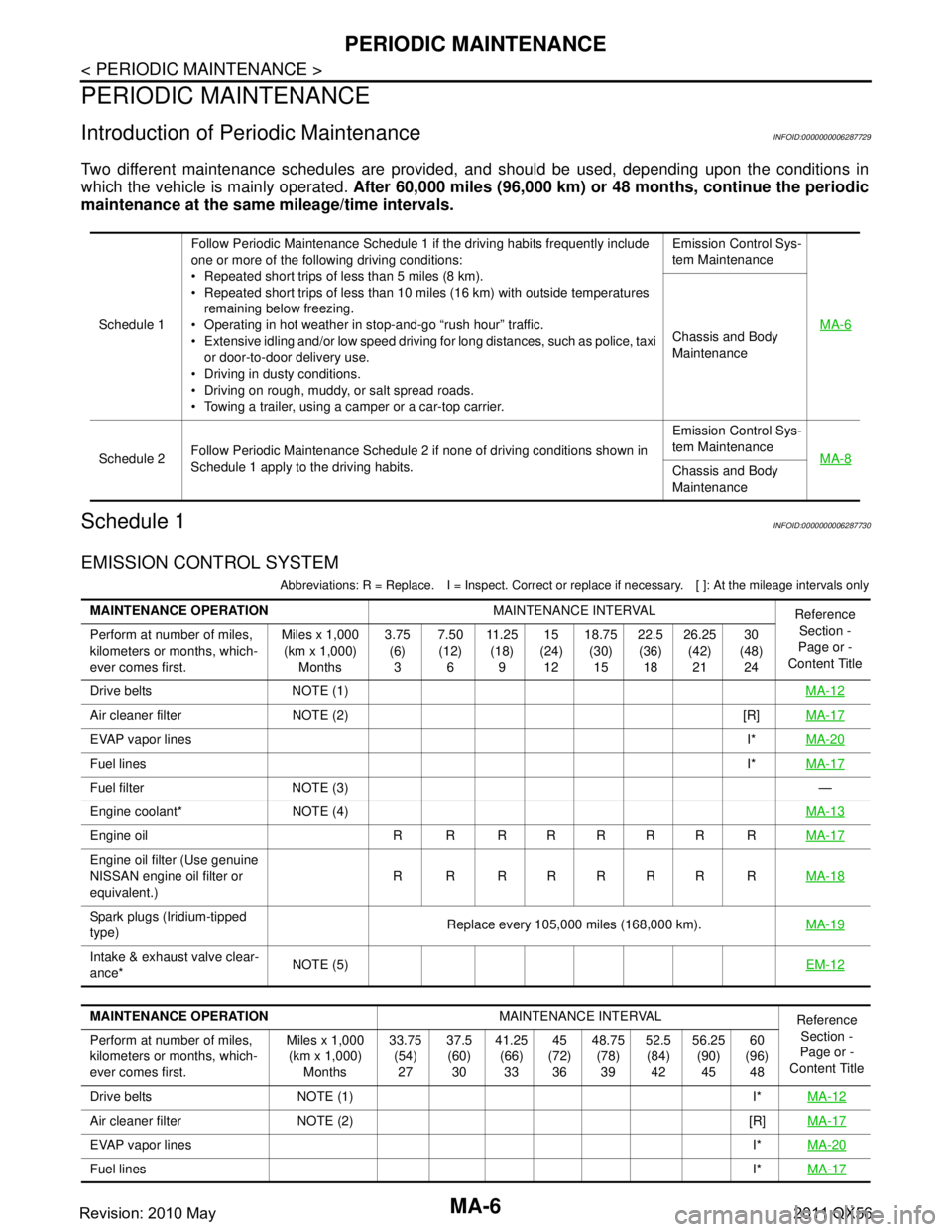
Introduction of Periodic MaintenanceINFOID:0000000006287729
Two different maintenance schedules are provided, and should be used, depending upon the conditions in
which the vehicle is mainly operated. After 60,000 miles (96,000 km) or 48 months, continue the periodic
maintenance at the same mileage/time intervals.
Schedule 1INFOID:0000000006287730
EMISSION CONTROL SYSTEM
Abbreviations: R = Replace. I = Inspec t. Correct or replace if necessary. [ ]: At the mileage intervals only
Schedule 1Follow Periodic Maintenance Schedule 1 if the driving habits frequently include
one or more of the following driving conditions:
Repeated short trips of less than 5 miles (8 km).
Repeated short trips of less than 10 miles (16 km) with outside temperatures
remaining below freezing.
Operating in hot weather in stop-and-go “rush hour” traffic.
Extensive idling and/or low speed driving for long distances, such as police, taxi
or door-to-door delivery use.
Driving in dusty conditions.
Driving on rough, muddy, or salt spread roads.
Towing a trailer, using a camper or a car-top carrier. Emission Control Sys-
tem Maintenance
MA-6Chassis and Body
Maintenance
Schedule 2 Follow Periodic Maintenance Schedule 2 if none of driving conditions shown in
Schedule 1 apply to the driving habits. Emission Control Sys-
tem Maintenance
MA-8
Chassis and Body
Maintenance
MAINTENANCE OPERATION MAINTENANCE INTERVAL
Reference
Section -
Page or -
Content Title
Perform at number of miles,
kilometers or months, which-
ever comes first. Miles x 1,000
(km x 1,000) Months 3.75
(6)3 7.50
(12) 6 11 . 2 5
(18) 9 15
(24) 12 18.75
(30)15 22.5
(36) 18 26.25
(42)21 30
(48) 24
Drive belts NOTE (1) MA-12
Air cleaner filter NOTE (2) [R]MA-17
EVAP vapor linesI*MA-20
Fuel lines I*MA-17
Fuel filter NOTE (3) —
Engine coolant* NOTE (4) MA-13
Engine oil R R R R R R R RMA-17
Engine oil filter (Use genuine
NISSAN engine oil filter or
equivalent.)R R RRRRR R
MA-18
Spark plugs (Iridium-tipped
type)Replace every 105,000 miles (168,000 km).
MA-19
Intake & exhaust valve clear-
ance*NOTE (5)
EM-12
MAINTENANCE OPERATIONMAINTENANCE INTERVAL
Reference
Section -
Page or -
Content Title
Perform at number of miles,
kilometers or months, which-
ever comes first. Miles x 1,000
(km x 1,000) Months 33.75
(54)27 37.5
(60) 30 41.25
(66)33 45
(72) 36 48.75
(78)39 52.5
(84) 42 56.25
(90)45 60
(96) 48
Drive belts NOTE (1) I* MA-12
Air cleaner filter NOTE (2) [R]MA-17
EVAP vapor linesI*MA-20
Fuel lines I*MA-17
Revision: 2010 May2011 QX56