2011 INFINITI QX56 air filter
[x] Cancel search: air filterPage 3678 of 5598
MA-8
< PERIODIC MAINTENANCE >
PERIODIC MAINTENANCE
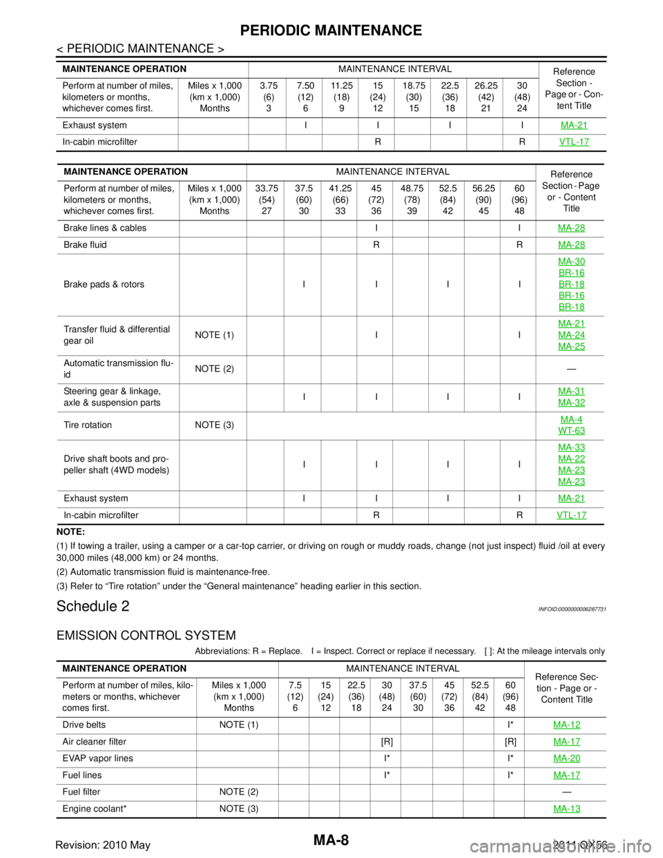
NOTE:
(1) If towing a trailer, using a camper or a car-top carrier, or driving on rough or muddy roads, change (not just inspect) fluid /oil at every
30,000 miles (48,000 km) or 24 months.
(2) Automatic transmission fluid is maintenance-free.
(3) Refer to “Tire rotation” unde r the “General maintenance” heading earlier in this section.
Schedule 2INFOID:0000000006287731
EMISSION CONTROL SYSTEM
Abbreviations: R = Replace. I = Inspec t. Correct or replace if necessary. [ ]: At the mileage intervals only
Exhaust system I I I I MA-21
In-cabin microfilter R RVTL-17
MAINTENANCE OPERATIONMAINTENANCE INTERVAL
Reference
Section -
Page or - Con- tent Title
Perform at number of miles,
kilometers or months,
whichever comes first. Miles x 1,000
(km x 1,000)
Months 3.75
(6)
3 7.50
(12)
6 11 . 2 5
(18)
9 15
(24)
12 18.75
(30)
15 22.5
(36)
18 26.25
(42)
21 30
(48)
24
MAINTENANCE OPERATION MAINTENANCE INTERVAL
Reference
Section - Page
or - Content Title
Perform at number of miles,
kilometers or months,
whichever comes first. Miles x 1,000
(km x 1,000) Months 33.75
(54)27 37.5
(60) 30 41.25
(66)33 45
(72) 36 48.75
(78)39 52.5
(84) 42 56.25
(90)45 60
(96) 48
Brake lines & cables I I MA-28
Brake fluid R RMA-28
Brake pads & rotors I I I IMA-30
BR-16
BR-18
BR-16
BR-18
Transfer fluid & differential
gear oil
NOTE (1) I I MA-21MA-24
MA-25
Automatic transmission flu-
id
NOTE (2)
—
Steering gear & linkage,
axle & suspension parts IIII
MA-31
MA-32
Tire rotation NOTE (3) MA-4WT-63
Drive shaft boots and pro-
peller shaft (4WD models)IIII MA-33MA-22
MA-23
MA-23
Exhaust system I I I I
MA-21
In-cabin microfilter R RVTL-17
MAINTENANCE OPERATIONMAINTENANCE INTERVAL
Reference Sec-
tion - Page or -
Content Title
Perform at number of miles, kilo-
meters or months, whichever
comes first. Miles x 1,000
(km x 1,000)
Months 7.5
(12)
6 15
(24)
12 22.5
(36)
18 30
(48)
24 37.5
(60)
30 45
(72)
36 52.5
(84)
42 60
(96)
48
Drive belts NOTE (1) I* MA-12
Air cleaner filter [R] [R]MA-17
EVAP vapor lines I* I*MA-20
Fuel lines I* I*MA-17
Fuel filter NOTE (2) —
Engine coolant* NOTE (3) MA-13
Revision: 2010 May2011 QX56
Page 3687 of 5598
ENGINE MAINTENANCEMA-17
< PERIODIC MAINTENANCE >
C
DE
F
G H
I
J
K L
M B
MA
N
O A
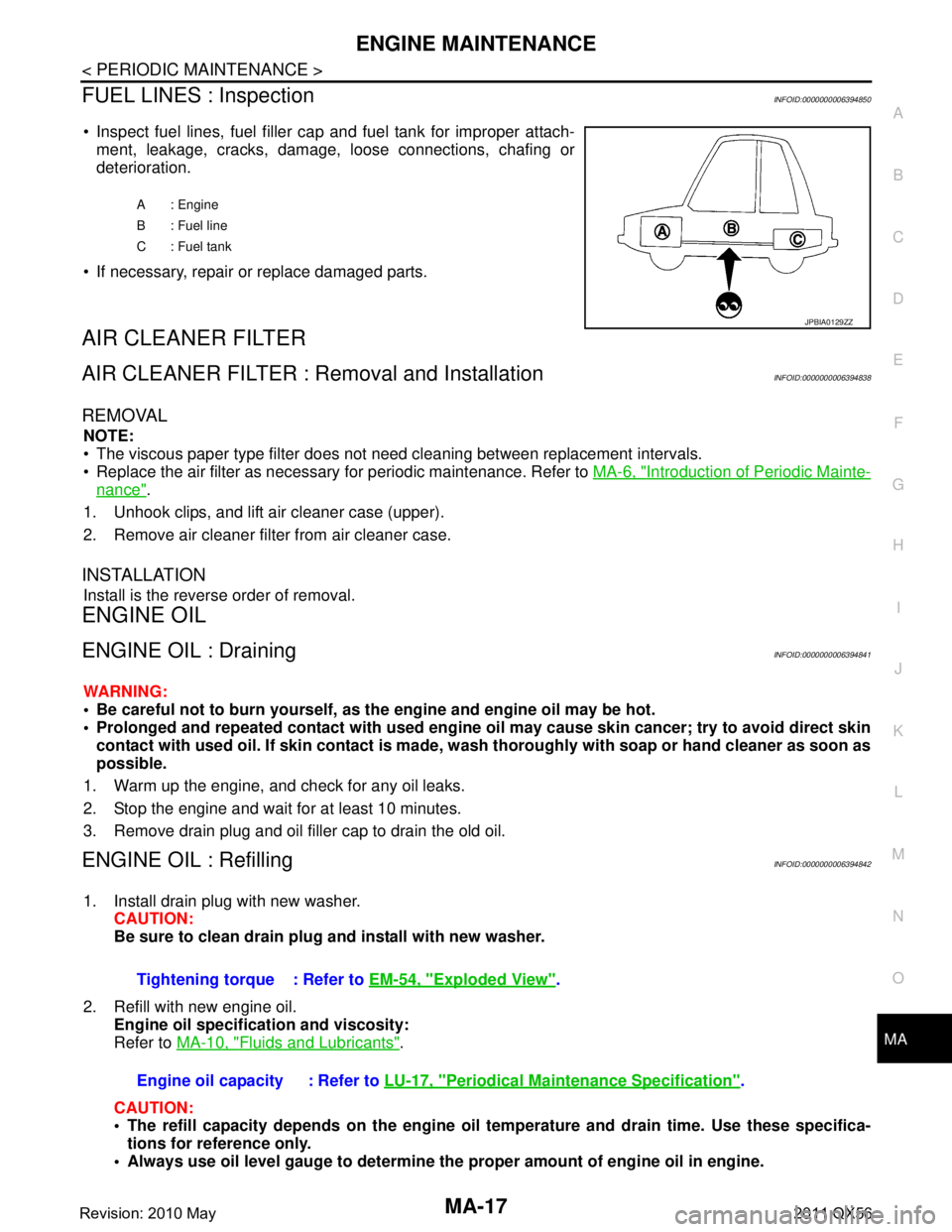
FUEL LINES : InspectionINFOID:0000000006394850
Inspect fuel lines, fuel filler cap and fuel tank for improper attach-
ment, leakage, cracks, damage, loose connections, chafing or
deterioration.
If necessary, repair or replace damaged parts.
AIR CLEANER FILTER
AIR CLEANER FILTER : Removal and InstallationINFOID:0000000006394838
REMOVAL
NOTE:
The viscous paper type filter does not need cleaning between replacement intervals.
Replace the air filter as necessary for periodic maintenance. Refer to MA-6, "
Introduction of Periodic Mainte-
nance".
1. Unhook clips, and lift air cleaner case (upper).
2. Remove air cleaner filter from air cleaner case.
INSTALLATION
Install is the reverse order of removal.
ENGINE OIL
ENGINE OIL : DrainingINFOID:0000000006394841
WARNING:
Be careful not to burn yourself, as th e engine and engine oil may be hot.
Prolonged and repeated contact with used engine oil may cau se skin cancer; try to avoid direct skin
contact with used oil. If skin contact is made, w ash thoroughly with soap or hand cleaner as soon as
possible.
1. Warm up the engine, and check for any oil leaks.
2. Stop the engine and wait for at least 10 minutes.
3. Remove drain plug and oil filler cap to drain the old oil.
ENGINE OIL : RefillingINFOID:0000000006394842
1. Install drain plug with new washer. CAUTION:
Be sure to clean drain plug and install with new washer.
2. Refill with new engine oil. Engine oil specificat ion and viscosity:
Refer to MA-10, "
Fluids and Lubricants".
CAUTION:
The refill capacity depends on the engine oi l temperature and drain time. Use these specifica-
tions for reference only.
Always use oil level gauge to determine the proper amount of engine oil in engine.
A : Engine
B : Fuel line
C : Fuel tank
JPBIA0129ZZ
Tightening torque : Refer to EM-54, "Exploded View".
Engine oil capacity : Refer to LU-17, "
Periodical Maintenance Specification".
Revision: 2010 May2011 QX56
Page 4398 of 5598
![INFINITI QX56 2011 Factory Service Manual
SCS-38
< REMOVAL AND INSTALLATION >[HBMC]
HYDRAULIC BODY-MOTION CONTROL SYSTEM
Completely engage hooks on frame when installing accumulator
assembly.
ACCUMULATOR : InspectionINFOID:0000000006256026 INFINITI QX56 2011 Factory Service Manual
SCS-38
< REMOVAL AND INSTALLATION >[HBMC]
HYDRAULIC BODY-MOTION CONTROL SYSTEM
Completely engage hooks on frame when installing accumulator
assembly.
ACCUMULATOR : InspectionINFOID:0000000006256026](/manual-img/42/57033/w960_57033-4397.png)
SCS-38
< REMOVAL AND INSTALLATION >[HBMC]
HYDRAULIC BODY-MOTION CONTROL SYSTEM
Completely engage hooks on frame when installing accumulator
assembly.
ACCUMULATOR : InspectionINFOID:0000000006256026
INSPECTION AFTER REMOVAL
O-ring must be free of scratches and damage.
Pipe and tube must be free of scratches and damage.
INSPECTION AFTER INSTALLATION
Check oil leakage, twists, deformation, cont act with other parts, and loose connections.
ADJUSTMENT AFTER INSTALLATION
Perform air bleeding. Refer to SCS-18, "Work Procedure".
ACCUMULATOR : DisposalINFOID:0000000006256027
CAUTION:
Always wear safety goggles.
Always wear safety gloves.
Be careful since pressure is higher when temperature is high.
Be careful since metal shavings or oi l may be blown away by compressed gas.
Discard drained oil in accordance with local laws and regulations.
WORK PROCEDURE
1. Remove both tanks using an oil filter wrench.
2. Secure tank using a vise.
3. Drill a hole as shown in the figure ( �z) using an electric drill.
Drain gas and oil.
NOTE:
Gas is colorless, odorless, and harmless.
Use an electric drill with a drill bit of approximately 4 mm (0.16 in).
Drilling a hole is easier when electric drill speed is slow.
PPMU, MIDDLE TUBE AS SEMBLY, PPMU PIPE
JSEIA0202ZZ
JSEIA0182ZZ
Revision: 2010 May2011 QX56
Page 4403 of 5598
![INFINITI QX56 2011 Factory Service Manual
HYDRAULIC BODY-MOTION CONTROL SYSTEMSCS-43
< REMOVAL AND INSTALLATION > [HBMC]
C
D
F
G H
I
J
K L
M A
B
SCS
N
O P
PPMU, MIDDLE TUBE ASSEMBLY, PPMU PIPE : InspectionINFOID:0000000006256030
INSPECTION A INFINITI QX56 2011 Factory Service Manual
HYDRAULIC BODY-MOTION CONTROL SYSTEMSCS-43
< REMOVAL AND INSTALLATION > [HBMC]
C
D
F
G H
I
J
K L
M A
B
SCS
N
O P
PPMU, MIDDLE TUBE ASSEMBLY, PPMU PIPE : InspectionINFOID:0000000006256030
INSPECTION A](/manual-img/42/57033/w960_57033-4402.png)
HYDRAULIC BODY-MOTION CONTROL SYSTEMSCS-43
< REMOVAL AND INSTALLATION > [HBMC]
C
D
F
G H
I
J
K L
M A
B
SCS
N
O P
PPMU, MIDDLE TUBE ASSEMBLY, PPMU PIPE : InspectionINFOID:0000000006256030
INSPECTION AFTER REMOVAL
O-ring must be free of scratches and damage.
Pipe and tube must be free of scratches and damage.
INSPECTION AFTER INSTALLATION
Check oil leakage, twists, deformation, contact with other parts, and loose connections.
ADJUSTMENT AFTER INSTALLATION
Perform air bleeding. Refer to SCS-18, "Work Procedure".
PPMU, MIDDLE TUBE ASSEMBLY , PPMU PIPE : DisposalINFOID:0000000006256031
CAUTION:
Always wear safety goggles.
Always wear safety gloves.
Be careful since pressure is higher when temperature is high.
Be careful since metal shavings or oi l may be blown away by compressed gas.
Discard drained oil in accordance wi th local laws and regulations.
WORK PROCEDURE
1. Remove both tanks using an oil filter wrench.
2. Secure tank using a vise.
3. Drill a hole as shown in the figure ( �z) using an electric drill.
Drain gas and oil.
NOTE:
Gas is colorless, odorless, and harmless.
Use an electric drill with a drill bit of approximately 4 mm (0.16
in).
Drilling a hole is easier when electric drill speed is slow.
REAR TUBE ASSEMBLY
JSEIA0182ZZ
Revision: 2010 May2011 QX56
Page 4461 of 5598

SE-2
SECOND HEATED SEAT SYSTEM : System De-
scription ..................................................................
16
CLIMATE CONTROLLED SEAT SYSTEM ........... ...17
CLIMATE CONTROLLED SEAT SYSTEM : Sys-
tem Diagram ........................................................ ...
17
CLIMATE CONTROLLED SEAT SYSTEM : Sys-
tem Description .................................................... ...
17
CLIMATE CONTROLLED SEAT SYSTEM : Fail-
safe .........................................................................
17
ECU DIAGNOSIS INFORMATION ..............20
CLIMATE CONTROLLED SEAT CONTROL
UNIT ................................................................ ...
20
Reference Value .................................................. ...20
Fail-safe ..................................................................21
WIRING DIAGRAM .....................................24
POWER SEAT CONTROL SYSTEM (PAS-
SENGER SIDE) ............................................... ...
24
Wiring Diagram .................................................... ...24
LUMBAR SUPPORT SYSTEM ..........................28
Wiring Diagram .................................................... ...28
SECOND SEAT POWER UNLOCK SYSTEM ...33
Wiring Diagram .......................................................33
THIRD SEAT SEATBACK POWER FOLDING
SYSTEM .......................................................... ...
39
Wiring Diagram .................................................... ...39
FRONT HEATED SEAT SYSTEM .....................45
Wiring Diagram .................................................... ...45
SECOND HEATED SEAT SYSTEM ..................50
Wiring Diagram .................................................... ...50
CLIMATE CONTROLLED SEAT SYSTEM .......55
Wiring Diagram .................................................... ...55
BASIC INSPECTION ...................................66
DIAGNOSIS AND REPAIR WORK FLOW ..... ...66
Work Flow ............................................................ ...66
DTC/CIRCUIT DIAGNOSIS ...................... ...67
POWER SUPPLY AND GROUND CIRCUIT .. ...67
CLIMATE CONTROLLED SEAT CONTROL UNIT ...67
CLIMATE CONTROLLED SEAT CONTROL UNIT
: Diagnosis Procedure ............................................
67
CLIMATE CONTROLLED SEAT CONTROL UNIT
: Component Inspection ..........................................
70
CLIMATE CONTROLLED SEAT SWITCH ........72
Component Function Check .............................. ...72
Diagnosis Procedure ..............................................72
Component Inspection ............................................74
SEATBACK THERMAL ELECTRIC UNIT ........75
Component Function Check ............................... ...75
Diagnosis Procedure ...............................................75
SEATBACK THERMAL ELECTRIC UNIT
SENSOR ............................................................
77
Component Function Check ............................... ...77
Diagnosis Procedure ...............................................77
Component Inspection ............................................78
SEAT CUSHION THERMAL ELECTRIC UNIT ...79
Component Function Check ............................... ...79
Diagnosis Procedure ...............................................79
SEAT CUSHION THERMAL ELECTRIC UNIT
SENSOR ............................................................
81
Component Function Check ............................... ...81
Diagnosis Procedure ...............................................81
Component Inspection ............................................82
CLIMATE CONTROLLED SEATBACK
BLOWER MOTOR .............................................
83
Component Function Check ............................... ...83
Diagnosis Procedure ...............................................83
CLIMATE CONTROLLED SEAT CUSHION
BLOWER MOTOR .............................................
86
Component Function Check ............................... ...86
Diagnosis Procedure ...............................................86
CLIMATE CONTROLLED SEAT SWITCH IN-
DICATOR ...........................................................
89
Component Function Check ............................... ...89
Diagnosis Procedure ...............................................89
CLIMATE CONTROLLED SEAT BLOWER
FILTER ...............................................................
91
SEATBACK BLOWER MOTOR ............................. ...91
SEATBACK BLOWER MOTOR : Diagnosis Pro-
cedure .....................................................................
91
SEAT CUSHION BLOWER MOTOR ..................... ...91
SEAT CUSHION BLOWER MOTOR : Diagnosis
Procedure ...............................................................
91
SYMPTOM DIAGNOSIS ............................92
CLIMATE CONTROLLED SEAT DOES NOT
OPERATE. ...................................................... ...
92
Diagnosis Procedure ............................................ ...92
TEMPERATURE ADJUSTMENT IS IMPOSSI-
BLE ....................................................................
94
SEATBACK ............................................................ ...94
SEATBACK : Diagnosis Procedure ........................94
SEAT CUSHION ..................................................... ...94
SEAT CUSHION : Diagnosis Procedure .................94
Revision: 2010 May2011 QX56
Page 4553 of 5598
SE-94
< SYMPTOM DIAGNOSIS >
TEMPERATURE ADJUSTMENT IS IMPOSSIBLE
TEMPERATURE ADJUSTMENT IS IMPOSSIBLE
SEATBACK
SEATBACK : Diagnosis ProcedureINFOID:0000000006217413
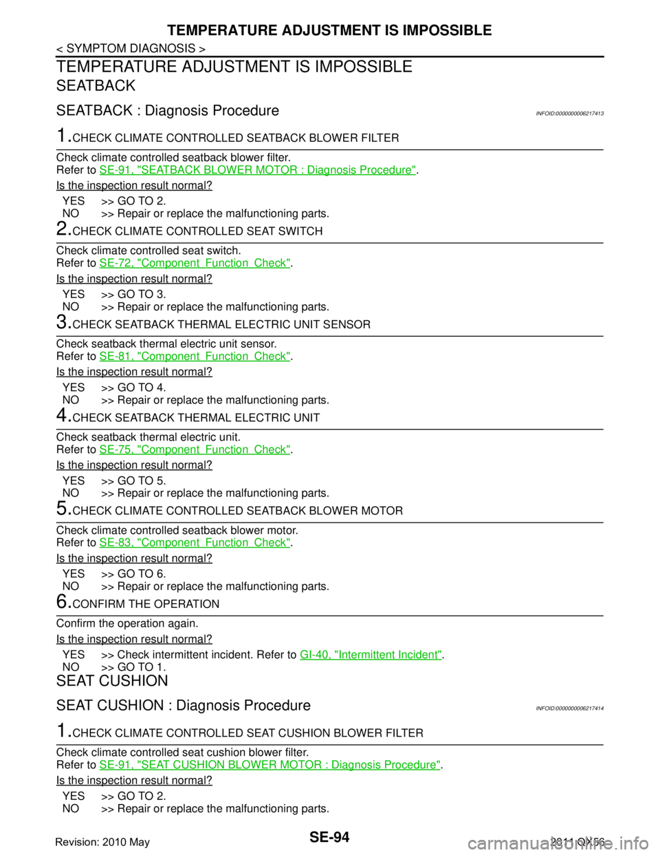
1.CHECK CLIMATE CONTROLLED SEATBACK BLOWER FILTER
Check climate controlled seatback blower filter.
Refer to SE-91, "
SEATBACK BLOWER MOTOR : Diagnosis Procedure".
Is the inspection result normal?
YES >> GO TO 2.
NO >> Repair or replace the malfunctioning parts.
2.CHECK CLIMATE CONTROLLED SEAT SWITCH
Check climate controlled seat switch.
Refer to SE-72, "
ComponentFunctionCheck".
Is the inspection result normal?
YES >> GO TO 3.
NO >> Repair or replace the malfunctioning parts.
3.CHECK SEATBACK THERMAL ELECTRIC UNIT SENSOR
Check seatback thermal electric unit sensor.
Refer to SE-81, "
ComponentFunctionCheck".
Is the inspection result normal?
YES >> GO TO 4.
NO >> Repair or replace the malfunctioning parts.
4.CHECK SEATBACK THERMAL ELECTRIC UNIT
Check seatback thermal electric unit.
Refer to SE-75, "
ComponentFunctionCheck".
Is the inspection result normal?
YES >> GO TO 5.
NO >> Repair or replace the malfunctioning parts.
5.CHECK CLIMATE CONTROLLED SEATBACK BLOWER MOTOR
Check climate controlled seatback blower motor.
Refer to SE-83, "
ComponentFunctionCheck".
Is the inspection result normal?
YES >> GO TO 6.
NO >> Repair or replace the malfunctioning parts.
6.CONFIRM THE OPERATION
Confirm the operation again.
Is the inspection result normal?
YES >> Check intermittent incident. Refer to GI-40, "Intermittent Incident".
NO >> GO TO 1.
SEAT CUSHION
SEAT CUSHION : Diagnosis ProcedureINFOID:0000000006217414
1.CHECK CLIMATE CONTROLLED SEAT CUSHION BLOWER FILTER
Check climate controlled seat cushion blower filter.
Refer to SE-91, "
SEAT CUSHION BLOWER MOTOR : Diagnosis Procedure".
Is the inspection result normal?
YES >> GO TO 2.
NO >> Repair or replace the malfunctioning parts.
Revision: 2010 May2011 QX56
Page 4569 of 5598
SE-110
< REMOVAL AND INSTALLATION >
FRONT SEAT
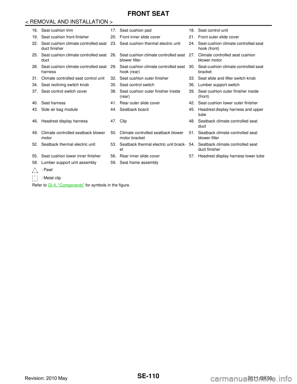
16. Seat cushion trim 17. Seat cushion pad 18. Seat control unit
19. Seat cushion front finisher 20. Front inner slide cover 21. Front outer slide cover
22. Seat cushion climate controlled seat duct finisher 23. Seat cushion thermal electric unit 24. Seat cushion climate controlled seat
hook (front)
25. Seat cushion climate controlled seat duct 26. Seat cushion climate controlled seat
blower filter 27. Climate controlled seat cushion
blower motor
28. Seat cushion climate controlled seat harness 29. Seat cushion climate controlled seat
hook (rear) 30. Seat cushion climate controlled seat
bracket
31. Climate controlled seat control unit 32. Seat cushion outer finisher 33. Seat slide and lifter switch knob
34. Seat reclining switch knob 35. Seat control switch 36. Lumber support switch
37. Seat control switch cover 38. Seat cushion outer finisher inside (rear)39. Seat cushion outer finisher inside
(front)
40. Seat harness 41. Rear outer slide cover 42. Seat cushion lower outer finisher
43. Side air bag module 44. Seatback board 45. Headrest display harness and upper tube
46. Headrest display harness 47. Clip 48. Seatback climate controlled seat duct
49. Climate controlled seatback blower motor 50. Climate controlled seatback blower
motor bracket 51. Seatback climate controlled seat
blower filter
52. Seatback thermal electric unit 53. Seatback thermal electric unit brack- et54. Seatback climate controlled seat
duct finisher
55. Seat cushion lower inner finisher 56. Rear inner slide cover 57. Headrest display harness lower tube
58. Lumber support unit assembly 59. Seat frame assembly
: Pawl
: Metal clip
Refer to GI-4, "
Components" for symbols in the figure.
Revision: 2010 May2011 QX56
Page 4802 of 5598
COMPONENT PARTSSRC-9
< SYSTEM DESCRIPTION >
C
DE
F
G
I
J
K L
M A
B
SRC
N
O P
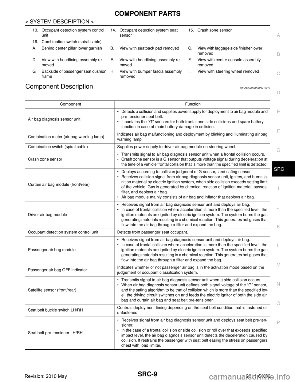
Component DescriptionINFOID:0000000006219949
13. Occupant detection system control unit 14. Occupant detection system seat
sensor 15. Crash zone sensor
16. Combination switch (spiral cable)
A. Behind center pillar lower garnish B. View with seatback pad removed C. View with laggage side finisher lower removed
D. View with headlining assembly re- moved E. View with headlining assembly re-
moved F. View with center console assembly
removed
G. Backside of passenger seat cushion frame H. View with bumper fascia assembly
removed I. View with steering wheel removed
Component Function
Air bag diagnosis sensor unit Detects a collision and supplies power supply for deployment to air bag module and
pre-tensioner seat belt.
It contains the “G” sensors for both frontal and side collisions and spare battery function in case of main battery damage in collision.
Combination meter (air bag warning lamp) Indicates air bag malfunctioning and deployment by blinking and illuminating air bag
warning lamp.
Combination switch (spiral cable) Supplies power supply to driver air bag module on steering wheel.
Crash zone sensor Transmits signal to air bag diagnosis sensor unit when a frontal collision occurs.
Crash zone sensor is a G sensor that outputs voltage signal during deceleration at
the time of a vehicle frontal collision that is more than the specified limit is detected.
Curtain air bag module (front/rear) Deploys according to collision judgment of G sensor, and safing sensor.
Receives collision signal from air bag diagnosis sensor unit, ignites, and burns ig-
nition material by electric ignition system, when side collision exceeds setting limit
of the vehicle. Gas is generated by chemical reaction of ignition material, passes
filter, and deploys air bag.
Air bag module mainly consists of air bag and inflator that deploys air bag.
Driver air bag module Receives signal from air bag diagnosis sensor unit and deploys air bag.
In case of frontal collision where acceleration is more than the specified level, the
ignition materials are ignited by electric ignition system. The system burns the gas
generating materials resulting in a chemical reaction. This generates hot gases that
flow into the air bag through a filter and expand the bag.
Occupant detection system control unit Detects front passenger seat occupant.
Passenger air bag module Receives signal from air bag diagnosis sensor unit and deploys air bag.
In case of frontal collision where acceleration is more than the specified level, the
ignition materials are ignited by electric ignition system. The system burns the gas
generating materials resulting in a chemical reaction. This generates hot gases that
flow into the air bag through a filter and expand the bag.
Passenger air bag OFF indicator Indicates whether or not passenger air bag is in the activation mode based on the
judgement of occupant classification system.
Satellite sensor (front/rear) Transmits signal to air bag diagnosis sensor unit when a side collision occurs.
When air bag diagnosis sensor unit defines both signal voltage of the “G” sensor,
and the safing algorithm to be that of collision which is more than the specified lev-
el, the driving circuit switches on and feeds the electric ignitor of both the side air
bag and curtain air bag and seat belt pre-tensioner.
Seat belt buckle switch LH/RH Controls deployment timing depending on the seat belt condition that is fastened or
unfastened.
Seat belt pre-tensioner LH/RH Receives signal from air bag diagnosis sensor unit and deploys seat belt pre-ten-
sioner.
In the case of a frontal collision or side collision or roll over that exceeds specified impact level, the air bag diagnosis sensor unit detects the deceleration caused by
collision. It restrains the passenger with seat belt easing the stress on passengers
chest with load limiter.
Revision: 2010 May2011 QX56