2011 INFINITI QX56 Map sensor
[x] Cancel search: Map sensorPage 2093 of 5598
DIAGNOSIS SYSTEM (ECM)EC-69
< SYSTEM DESCRIPTION > [VK56VD]
C
D
E
F
G H
I
J
K L
M A
EC
NP
O
FUEL INJ B1 msec
ECM-calculated injection pulse width of the fuel in-
jector on the Bank 1 side.
FUEL INJ B2 msec ECM-calculated injection pulse width of the fuel in-
jector on the Bank 2 side.
INT/V TIM (B1) °CA Indicates [ °CA] of intake camshaft advance angle.
INT/V TIM (B2)
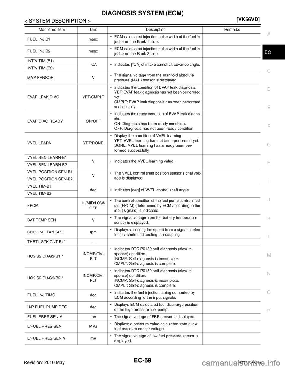
MAP SENSOR V The signal voltage from the manifold absolute
pressure (MAP) sensor is displayed.
EVAP LEAK DIAG YET/CMPLT Indicates the condition of EVAP leak diagnosis.
YET: EVAP leak diagnosis has not been performed
yet.
CMPLT: EVAP leak diagnosis has been performed
successfully.
EVAP DIAG READY ON/OFF Indicates the ready condition of EVAP leak diagno-
sis.
ON: Diagnosis has been ready condition.
OFF: Diagnosis has not been ready condition.
VVEL LEARN YET/DONE Display the conditi
on of VVEL learning
YET: VVEL learning has not been performed yet.
DONE: VVEL learning has already been per-
formed successfully.
VVEL SEN LEARN-B1 V Indicates the VVEL learning value.
VVEL SEN LEARN-B2
VVEL POSITION SEN-B1 V The VVEL control shaft position sensor signal volt-
age is displayed.
VVEL POSITION SEN-B2
VVEL TIM-B1
deg Indicates [deg] of VVEL control shaft angle.
VVEL TIM-B2
FPCM HI/MID/LOW/
OFF The control condition of the fuel pump control mod-
ule (FPCM) (determined by ECM according to the
input signals) is indicated.
BAT TEMP SEN V The signal voltage from the battery temperature
sensor is displayed.
COOLING FAN SPD rpm Displays a cooling fan speed from a signal of elec-
trically-controlled cooling fan coupling.
THRTL STK CNT B1* — —
HO2 S2 DIAG2(B1)* INCMP/CM-
PLT Indicates DTC P0139 self-diagnosis (slow re-
sponse) condition.
INCMP: Self-diagnosis is incomplete.
CMPLT: Self-diagnosis is complete.
HO2 S2 DIAG2(B2)* INCMP/CM-
PLT Indicates DTC P0159 self-diagnosis (slow re-
sponse) condition.
INCMP: Self-diagnosis is incomplete.
CMPLT: Self-diagnosis is complete.
FUEL INJ TIMG deg Indicates the fuel injection timing computed by
ECM according to the input signals.
H/P FUEL PUMP DEG deg Displays ECM-calculated fuel discharge position
of the high pressure fuel pump.
FUEL PRES SEN V mV The signal voltage of FRP sensor is displayed.
L/FUEL PRES SEN MPa Displays a pressure value calculated from a low
fuel pressure sensor voltage.
L/FUEL PRES SEN V mV The signal voltage of low fuel pressure sensor is
displayed.
Monitored item Unit Description Remarks
Revision: 2010 May2011 QX56
Page 2099 of 5598
ECM
EC-75
< ECU DIAGNOSIS INFORMATION > [VK56VD]
C
D
E
F
G H
I
J
K L
M A
EC
NP
O
BRAKE SW2
(Stop lamp switch)
Ignition switch: ON Brake pedal: Fully released OFF
Brake pedal: Slightly depressed ON
DIST SW Ignition switch: ON DISTANCE switch: Pressed ON
DISTANCE switch: Released OFF
CRUISE LAMP Ignition switch: ON MAIN switch: Pressed at the 1st time
→
at the 2nd time ON
→ OFF
AC EVA TEMP Engine: Running Indicates A/C evaporator
temperature sent from“uni-
fied meter and A/C amp.”.
AC EVA TARGET Engine: Running Indicates target A/C evapo-
rator temperature sentfrom
“unified meter and A/C
amp.”.
FAN DUTY Engine: Running 0 - 100%
ALT DUTY Engine: Idle 0 - 80%
BAT CUR SEN Engine speed: Idle
Battery: Fully charged*
2
Selector lever: P or N position
A/C switch: OFF
No load Approx. 2,600 - 3,500 mV
A/F ADJ-B1 Engine: Running −0.330 - 0.330
A/F ADJ-B2 Engine: Running −0.330 - 0.330
P/N POSI SW Ignition switch: ON Selector lever: P or N ON
Selector lever: Except above position OFF
INT/A TEMP SE Ignition switch: ON Indicates intake air temper-
ature
AC PRESS SEN Engine: Idle
Both A/C switch and blower fan switch: ON (Compressor operates) 1.0 - 4.0 V
FUEL PRES SEN Engine: After warming up
Selector lever: P or N position
A/C switch: OFF
No load Idle Approx. 2.74 Mpa
2,000 rpm Approx. 3.0 Mpa
FUEL INJ B1 Engine: After warming up
Selector lever: P or N position
A/C switch: OFF
No load Idle Approx. 1.4 msec
2,000 rpm Approx. 1.0 msec
FUEL INJ B2 Engine: After warming up
Selector lever: P or N position
A/C switch: OFF
No load Idle Approx. 1.4 msec
2,000 rpm Approx. 1.0 msec
INT/V TIM (B1) Engine: After warming up
Selector lever: P or N position
A/C switch: OFF
No load Idle
−5 - 5 °CA
2,000 rpm Approx. 0 - 30 °CA
INT/V TIM (B2) Engine: After warming up
Selector lever: P or N position
A/C switch: OFF
No load Idle
−5 - 5 °CA
2,000 rpm Approx. 0 - 30 °CA
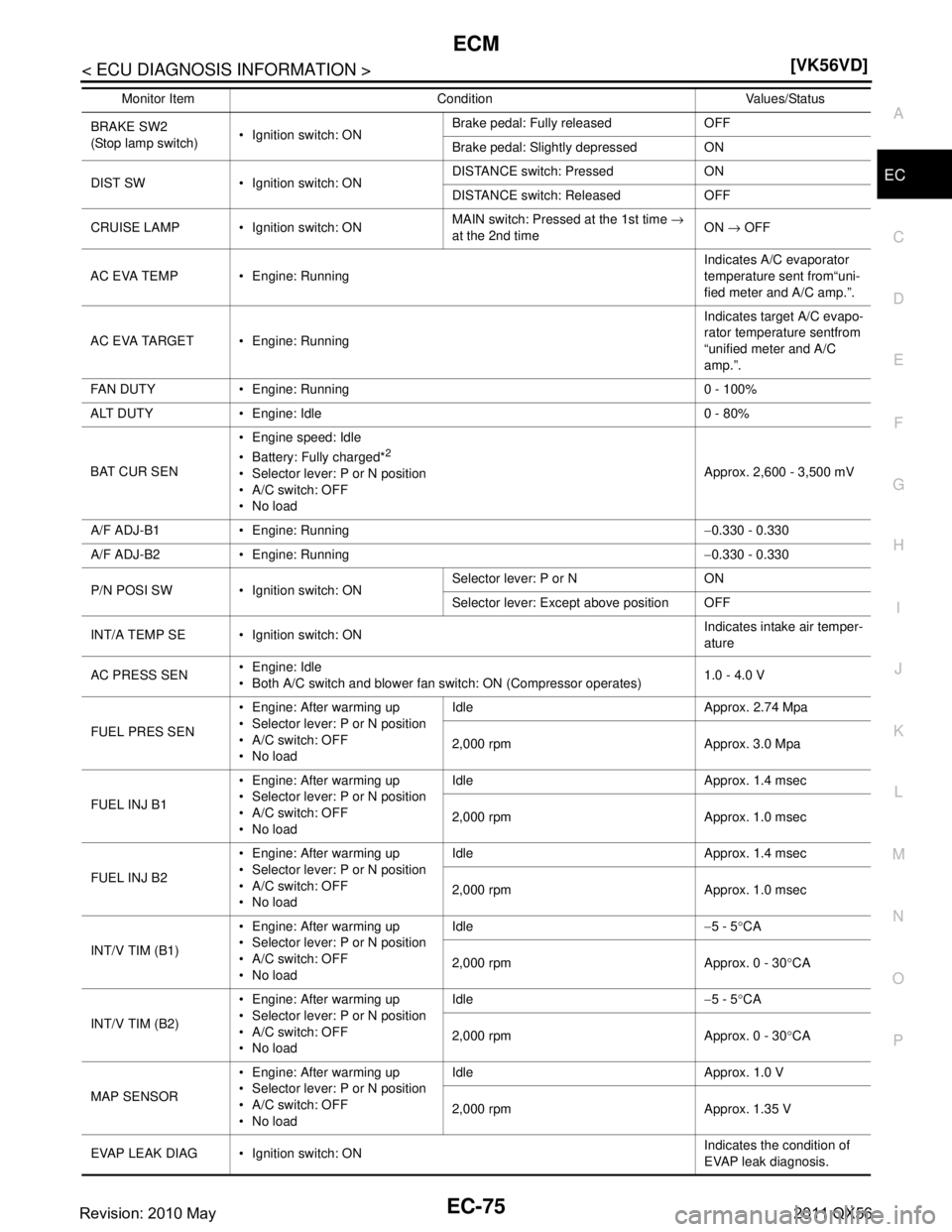
MAP SENSOR Engine: After warming up
Selector lever: P or N position
A/C switch: OFF
No load Idle Approx. 1.0 V
2,000 rpm Approx. 1.35 V
EVAP LEAK DIAG Ignition switch: ON Indicates the condition of
EVAP leak diagnosis.
Monitor Item Condition Values/Status
Revision: 2010 May2011 QX56
Page 2123 of 5598
ECM
EC-99
< ECU DIAGNOSIS INFORMATION > [VK56VD]
C
D
E
F
G H
I
J
K L
M A
EC
NP
OU1024 1024 VVEL CAN COMM CIRCUIT — 1
×EC-175
P0000 0000 NO DTC IS DETECTED.
FURTHER TESTING
MAY BE REQUIRED. ——
Blinking*6—
P0011 0011 INT/V TIM CONT-B1 ×2 ×
EC-177
P0021 0021 INT/V TIM CONT-B2 ×2 ×
P0031 0031 A/F SEN1 HTR (B1) — 2 ×
EC-181
P0032 0032 A/F SEN1 HTR (B1) — 2 ×
P0037 0037 HO2S2 HTR (B1) — 2 ×
EC-184
P0038 0038 HO2S2 HTR (B1) — 2 ×
P0051 0051 A/F SEN1 HTR (B2) — 2 ×
EC-181
P0052 0052 A/F SEN1 HTR (B2) — 2 ×
P0057 0057 HO2S2 HTR (B2) — 2 ×
EC-184
P0058 0058 HO2S2 HTR (B2) — 2 ×
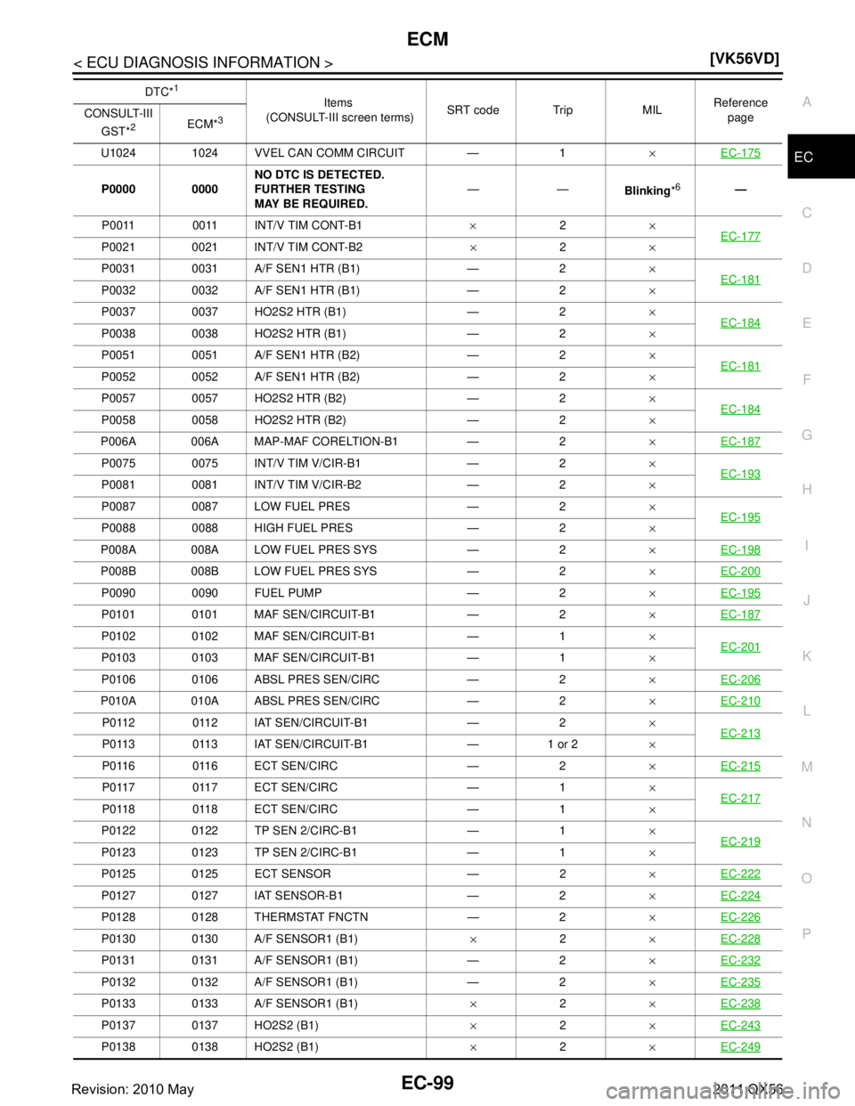
P006A 006A MAP-MAF CORELTION-B1 — 2 ×EC-187
P0075 0075 INT/V TIM V/CIR-B1 — 2 ×
EC-193
P0081 0081 INT/V TIM V/CIR-B2 — 2 ×
P0087 0087 LOW FUEL PRES — 2 ×
EC-195
P0088 0088 HIGH FUEL PRES — 2 ×
P008A 008A LOW FUEL PRES SYS — 2 ×EC-198
P008B 008B LOW FUEL PRES SYS — 2 ×EC-200
P0090 0090 FUEL PUMP — 2 ×EC-195
P0101 0101 MAF SEN/CIRCUIT-B1 — 2 ×EC-187
P0102 0102 MAF SEN/CIRCUIT-B1 — 1 ×
EC-201
P0103 0103 MAF SEN/CIRCUIT-B1 — 1 ×
P0106 0106 ABSL PRES SEN/CIRC — 2 ×EC-206
P010A 010A ABSL PRES SEN/CIRC — 2 ×EC-210
P0112 0112 IAT SEN/CIRCUIT-B1 — 2 ×
EC-213
P0113 0113 IAT SEN/CIRCUIT-B1 — 1 or 2 ×
P0116 0116 ECT SEN/CIRC — 2 ×EC-215
P0117 0117 ECT SEN/CIRC — 1 ×
EC-217
P0118 0118 ECT SEN/CIRC — 1 ×
P0122 0122 TP SEN 2/CIRC-B1 — 1 ×
EC-219
P0123 0123 TP SEN 2/CIRC-B1 — 1 ×
P0125 0125 ECT SENSOR — 2 ×EC-222
P0127 0127 IAT SENSOR-B1 — 2 ×EC-224
P0128 0128 THERMSTAT FNCTN — 2 ×EC-226
P0130 0130 A/F SENSOR1 (B1) ×2 ×EC-228
P0131 0131 A/F SENSOR1 (B1) — 2 ×EC-232
P0132 0132 A/F SENSOR1 (B1) — 2 ×EC-235
P0133 0133 A/F SENSOR1 (B1) ×2 ×EC-238
P0137 0137 HO2S2 (B1) ×2 ×EC-243
P0138 0138 HO2S2 (B1) ×2 ×EC-249
DTC*1
Items
(CONSULT-III screen terms) SRT code Trip MIL Reference
page
CONSULT-III
GST*
2ECM*3
Revision: 2010 May2011 QX56
Page 2211 of 5598
P006A, P0101 MAF SENSOREC-187
< DTC/CIRCUIT DIAGNOSIS > [VK56VD]
C
D
E
F
G H
I
J
K L
M A
EC
NP
O
P006A, P0101 MAF SENSOR
DTC LogicINFOID:0000000006288269
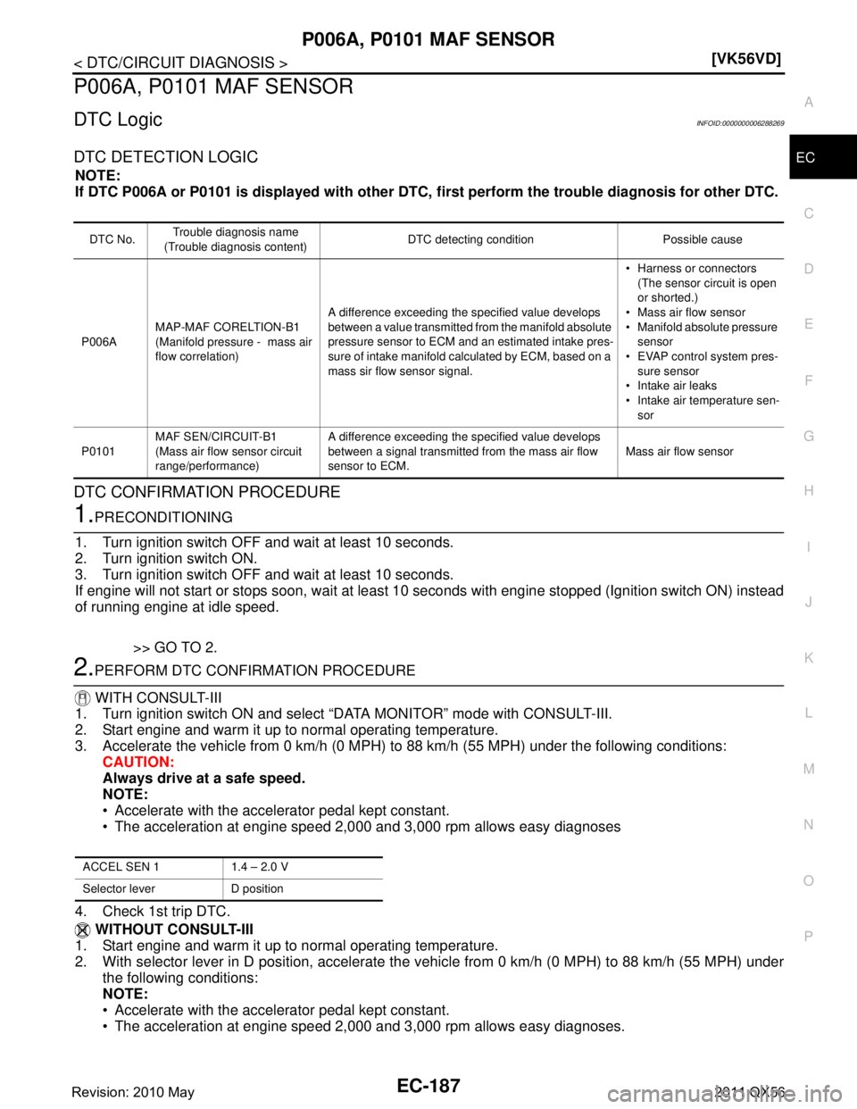
DTC DETECTION LOGIC
NOTE:
If DTC P006A or P0101 is displayed with other DTC,
first perform the trouble diagnosis for other DTC.
DTC CONFIRMATION PROCEDURE
1.PRECONDITIONING
1. Turn ignition switch OFF and wait at least 10 seconds.
2. Turn ignition switch ON.
3. Turn ignition switch OFF and wait at least 10 seconds.
If engine will not start or stops soon, wait at leas t 10 seconds with engine stopped (Ignition switch ON) instead
of running engine at idle speed.
>> GO TO 2.
2.PERFORM DTC CONFIRMATION PROCEDURE
WITH CONSULT-III
1. Turn ignition switch ON and select “DATA MONITOR” mode with CONSULT-III.
2. Start engine and warm it up to normal operating temperature.
3. Accelerate the vehicle from 0 km/h (0 MPH) to 88 km/h (55 MPH) under the following conditions:
CAUTION:
Always drive at a safe speed.
NOTE:
Accelerate with the accelerator pedal kept constant.
The acceleration at engine speed 2,000 and 3,000 rpm allows easy diagnoses
4. Check 1st trip DTC. WITHOUT CONSULT-III
1. Start engine and warm it up to normal operating temperature.
2. With selector lever in D position, accelerate the vehicle from 0 km/h (0 MPH) to 88 km/h (55 MPH) under
the following conditions:
NOTE:
Accelerate with the accelerator pedal kept constant.
The acceleration at engine speed 2,000 and 3,000 rpm allows easy diagnoses.
DTC No. Trouble diagnosis name
(Trouble diagnosis content) DTC detecting condition Possible cause
P006A MAP-MAF CORELTION-B1
(Manifold pressure
- mass air
flow correlation) A difference exceeding the specified value develops
between a value transmitted from the manifold absolute
pressure sensor to ECM and an estimated intake pres-
sure of intake manifold calculated by ECM, based on a
mass sir flow sensor signal. Harness or connectors
(The sensor circuit is open
or shorted.)
Mass air flow sensor
Manifold absolute pressure
sensor
EVAP control system pres-
sure sensor
Intake air leaks
Intake air temperature sen- sor
P0101 MAF SEN/CIRCUIT-B1
(Mass air flow sensor circuit
range/performance) A difference exceeding the specified value develops
between a signal transmitted from the mass air flow
sensor to ECM.
Mass air flow sensor
ACCEL SEN 1 1.4 – 2.0 V
Selector lever D position
Revision: 2010 May2011 QX56
Page 2213 of 5598
P006A, P0101 MAF SENSOREC-189
< DTC/CIRCUIT DIAGNOSIS > [VK56VD]
C
D
E
F
G H
I
J
K L
M A
EC
NP
O
Is the inspection result normal?
YES >> GO TO 5.
NO >> Repair open circuit, short to ground or short to power in harness or connectors.
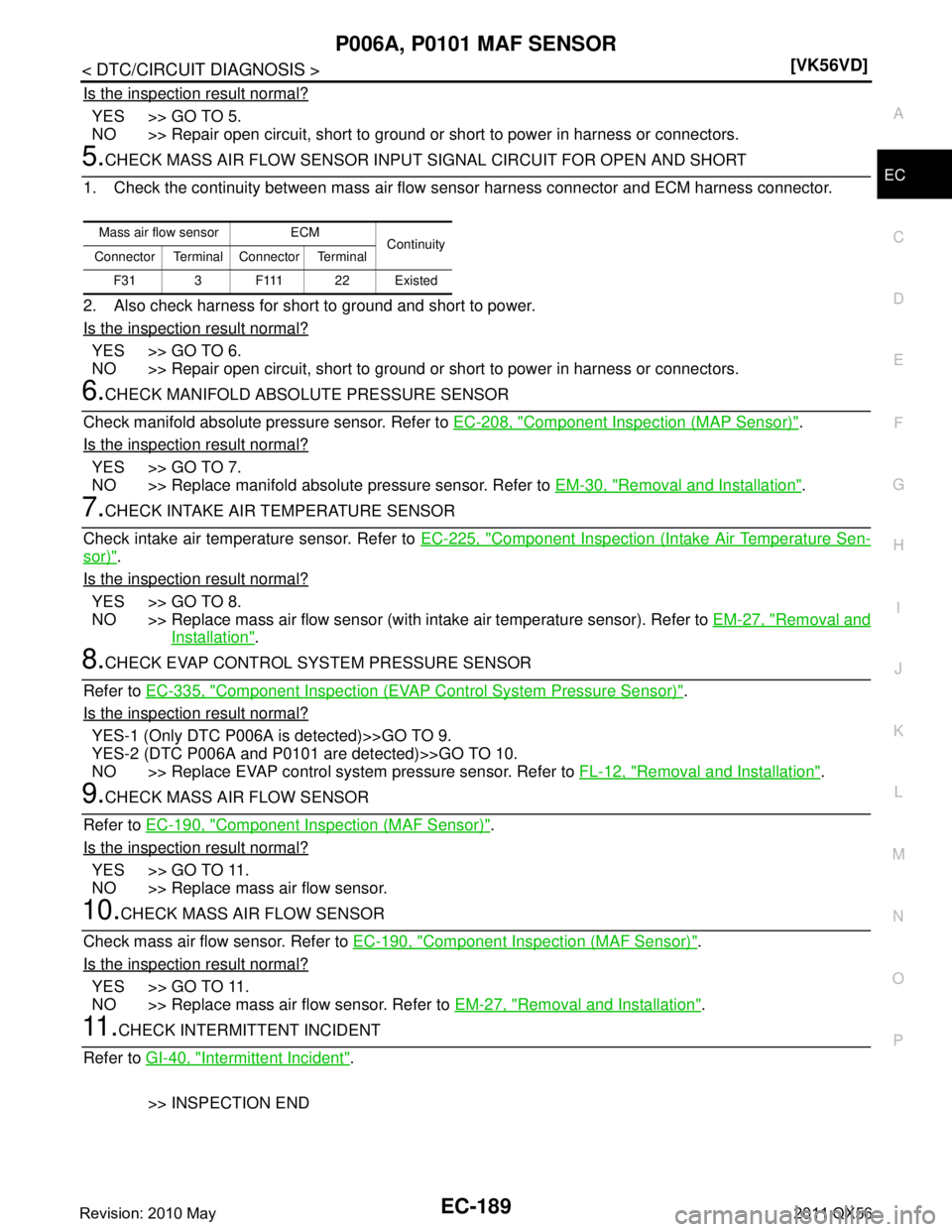
5.CHECK MASS AIR FLOW SENSOR INPUT SIGNAL CIRCUIT FOR OPEN AND SHORT
1. Check the continuity between mass air flow sensor harness connector and ECM harness connector.
2. Also check harness for short to ground and short to power.
Is the inspection result normal?
YES >> GO TO 6.
NO >> Repair open circuit, short to ground or short to power in harness or connectors.
6.CHECK MANIFOLD ABSO LUTE PRESSURE SENSOR
Check manifold absolute pressure sensor. Refer to EC-208, "
Component Inspection (MAP Sensor)".
Is the inspection result normal?
YES >> GO TO 7.
NO >> Replace manifold absolute pressure sensor. Refer to EM-30, "
Removal and Installation".
7.CHECK INTAKE AIR TEMPERATURE SENSOR
Check intake air temperature sensor. Refer to EC-225, "
Component Inspection (Intake Air Temperature Sen-
sor)".
Is the inspection result normal?
YES >> GO TO 8.
NO >> Replace mass air flow sensor (with intake air temperature sensor). Refer to EM-27, "
Removal and
Installation".
8.CHECK EVAP CONTROL SYSTEM PRESSURE SENSOR
Refer to EC-335, "
Component Inspection (EVAP Control System Pressure Sensor)".
Is the inspection result normal?
YES-1 (Only DTC P006A is detected)>>GO TO 9.
YES-2 (DTC P006A and P0101 are detected)>>GO TO 10.
NO >> Replace EVAP control system pressure sensor. Refer to FL-12, "
Removal and Installation".
9.CHECK MASS AIR FLOW SENSOR
Refer to EC-190, "
Component Inspection (MAF Sensor)".
Is the inspection result normal?
YES >> GO TO 11.
NO >> Replace mass air flow sensor.
10.CHECK MASS AIR FLOW SENSOR
Check mass air flow sensor. Refer to EC-190, "
Component Inspection (MAF Sensor)".
Is the inspection result normal?
YES >> GO TO 11.
NO >> Replace mass air flow sensor. Refer to EM-27, "
Removal and Installation".
11 .CHECK INTERMITTENT INCIDENT
Refer to GI-40, "
Intermittent Incident".
>> INSPECTION END
Mass air flow sensor ECM Continuity
Connector Terminal Connector Terminal
F 3 1 3 F 111 2 2 E x i s t e d
Revision: 2010 May2011 QX56
Page 2230 of 5598
EC-206
< DTC/CIRCUIT DIAGNOSIS >[VK56VD]
P0106 MANIFOLD ABSOL
UTE PRESSURE SENSOR
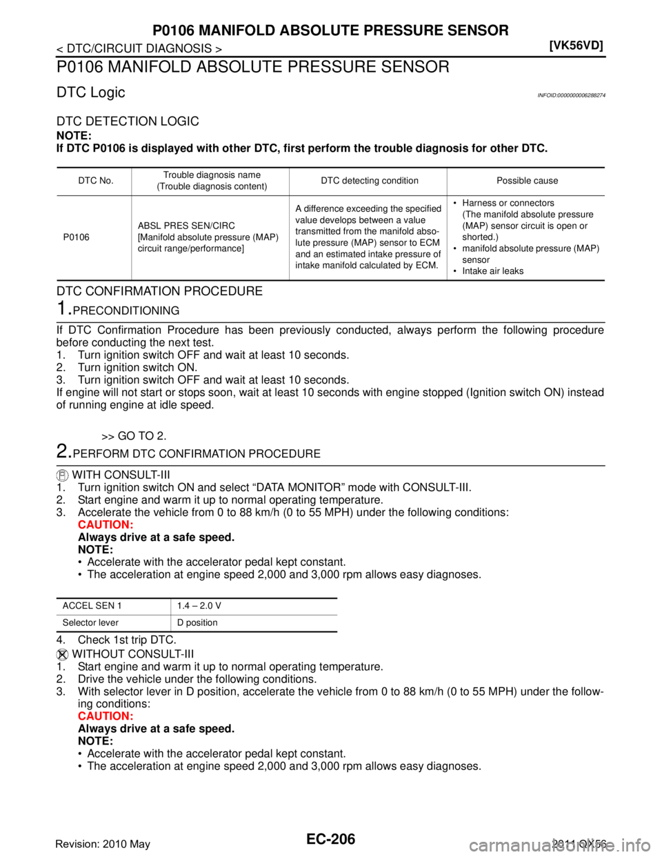
P0106 MANIFOLD ABSOLU TE PRESSURE SENSOR
DTC LogicINFOID:0000000006288274
DTC DETECTION LOGIC
NOTE:
If DTC P0106 is displayed with ot her DTC, first perform the trouble diagnosis for other DTC.
DTC CONFIRMATION PROCEDURE
1.PRECONDITIONING
If DTC Confirmation Procedure has been previously conducted, always perform the following procedure
before conducting the next test.
1. Turn ignition switch OFF and wait at least 10 seconds.
2. Turn ignition switch ON.
3. Turn ignition switch OFF and wait at least 10 seconds.
If engine will not start or stops soon, wait at leas t 10 seconds with engine stopped (Ignition switch ON) instead
of running engine at idle speed.
>> GO TO 2.
2.PERFORM DTC CONFIRMATION PROCEDURE
WITH CONSULT-III
1. Turn ignition switch ON and select “DATA MONITOR” mode with CONSULT-III.
2. Start engine and warm it up to normal operating temperature.
3. Accelerate the vehicle from 0 to 88 km/h (0 to 55 MPH) under the following conditions: CAUTION:
Always drive at a safe speed.
NOTE:
Accelerate with the accelerator pedal kept constant.
The acceleration at engine speed 2,000 and 3,000 rpm allows easy diagnoses.
4. Check 1st trip DTC. WITHOUT CONSULT-III
1. Start engine and warm it up to normal operating temperature.
2. Drive the vehicle under the following conditions.
3. With selector lever in D position, accelerate the v ehicle from 0 to 88 km/h (0 to 55 MPH) under the follow-
ing conditions:
CAUTION:
Always drive at a safe speed.
NOTE:
Accelerate with the accelerator pedal kept constant.
The acceleration at engine speed 2,000 and 3,000 rpm allows easy diagnoses.
DTC No. Trouble diagnosis name
(Trouble diagnosis content) DTC detecting condition Possible cause
P0106 ABSL PRES SEN/CIRC
[Manifold absolute pressure (MAP)
circuit range/performance] A difference exceeding the specified
value develops between a value
transmitted from the manifold abso-
lute pressure (MAP) sensor to ECM
and an estimated intake pressure of
intake manifold calculated by ECM. Harness or connectors
(The manifold absolute pressure
(MAP) sensor circuit is open or
shorted.)
manifold absolute pressure (MAP)
sensor
Intake air leaks
ACCEL SEN 1 1.4 – 2.0 V
Selector lever D position
Revision: 2010 May2011 QX56
Page 2231 of 5598
P0106 MANIFOLD ABSOLUTE PRESSURE SENSOREC-207
< DTC/CIRCUIT DIAGNOSIS > [VK56VD]
C
D
E
F
G H
I
J
K L
M A
EC
NP
O
4. Check 1st trip DTC.
Is 1st trip DTC detected?
YES >> Proceed to
EC-207, "Diagnosis Procedure".
NO >> INSPECTION END
Diagnosis ProcedureINFOID:0000000006288275
1.CHECK INTAKE SYSTEM
Check the following for connection.
Air duct
Vacuum hoses
Intake air passage between air duct and intake manifold.
Is the inspection result normal?
YES >> GO TO 2.
NO >> Repair or replace malfunctioning part.
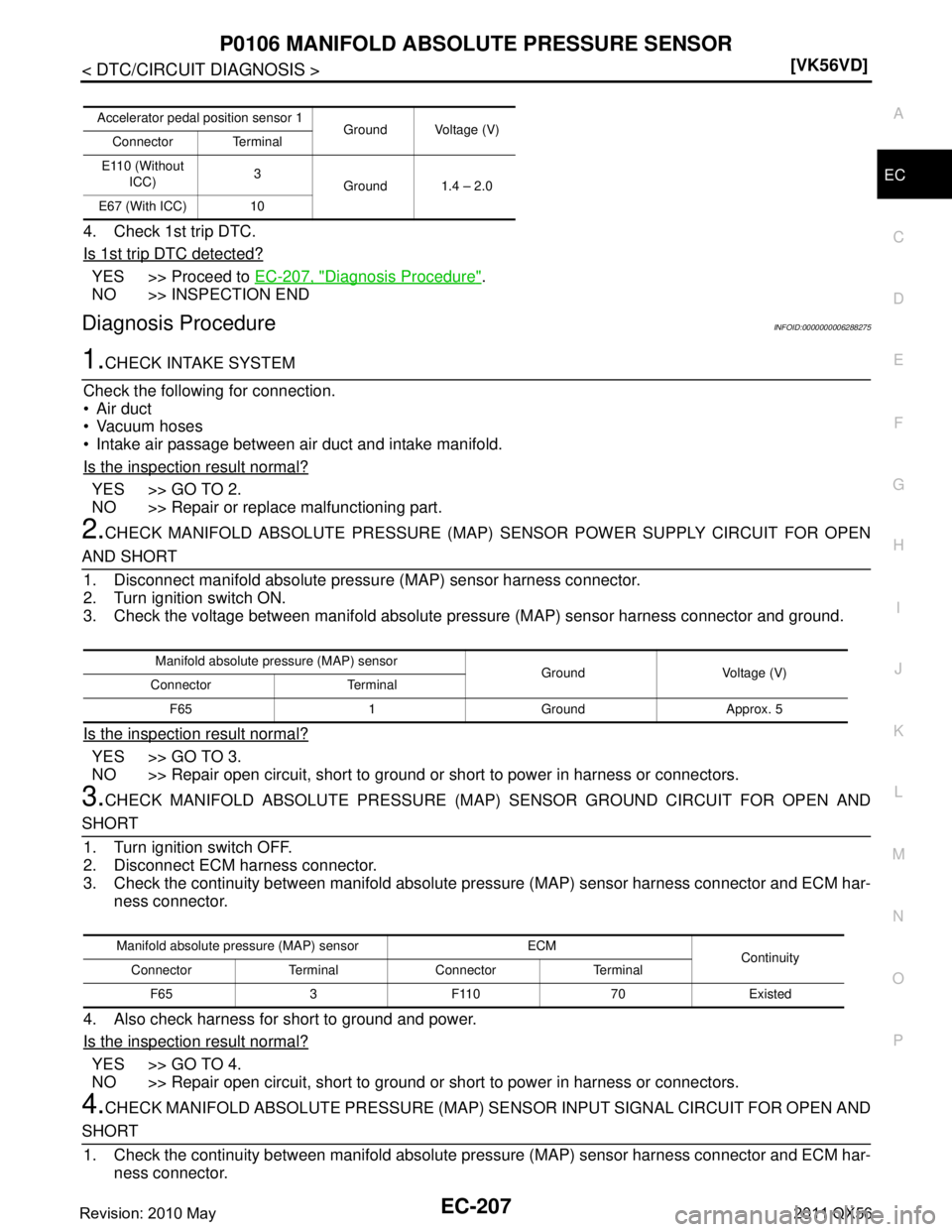
2.CHECK MANIFOLD ABSOLUTE PR ESSURE (MAP) SENSOR POWER SUPPLY CIRCUIT FOR OPEN
AND SHORT
1. Disconnect manifold absolute pressu re (MAP) sensor harness connector.
2. Turn ignition switch ON.
3. Check the voltage between manifold absolute pr essure (MAP) sensor harness connector and ground.
Is the inspection result normal?
YES >> GO TO 3.
NO >> Repair open circuit, short to ground or short to power in harness or connectors.
3.CHECK MANIFOLD ABSOLUTE PRESSURE (MAP) SENSOR GR OUND CIRCUIT FOR OPEN AND
SHORT
1. Turn ignition switch OFF.
2. Disconnect ECM harness connector.
3. Check the continuity between manifold absolute pressure (MAP) sensor harness connector and ECM har-
ness connector.
4. Also check harness for short to ground and power.
Is the inspection result normal?
YES >> GO TO 4.
NO >> Repair open circuit, short to ground or short to power in harness or connectors.
4.CHECK MANIFOLD ABSOLUTE PRESSURE (MAP) SE NSOR INPUT SIGNAL CIRCUIT FOR OPEN AND
SHORT
1. Check the continuity between manifold absolute pressure (MAP) sensor harness connector and ECM har-
ness connector.
Accelerator pedal position sensor 1 Ground Voltage (V)
Connector Terminal
E110 (Without ICC) 3
Ground 1.4 – 2.0
E67 (With ICC) 10
Manifold absolute pressure (MAP) sensor Ground Voltage (V)
Connector Terminal
F65 1 Ground Approx. 5
Manifold absolute pressure (MAP) sensor ECM Continuity
Connector Terminal Connector Terminal
F65 3 F110 70 Existed
Revision: 2010 May2011 QX56
Page 2232 of 5598
EC-208
< DTC/CIRCUIT DIAGNOSIS >[VK56VD]
P0106 MANIFOLD ABSOL
UTE PRESSURE SENSOR
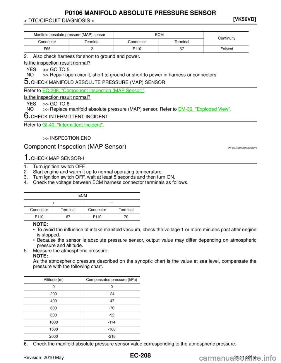
2. Also check harness for short to ground and power.
Is the inspection result normal?
YES >> GO TO 5.
NO >> Repair open circuit, short to ground or short to power in harness or connectors.
5.CHECK MANIFOLD ABSOLUTE PRESSURE (MAP) SENSOR
Refer to EC-208, "
Component Inspection (MAP Sensor)".
Is the inspection result normal?
YES >> GO TO 6.
NO >> Replace manifold absolute pr essure (MAP) sensor. Refer to EM-30, "
Exploded View".
6.CHECK INTERMITTENT INCIDENT
Refer to GI-40, "
Intermittent Incident".
>> INSPECTION END
Component Inspecti on (MAP Sensor)INFOID:0000000006288276
1.CHECK MAP SENSOR-I
1. Turn ignition switch OFF.
2. Start engine and warm it up to normal operating temperature.
3. Turn ignition switch OFF, wait at least 5 seconds and then turn ON.
4. Check the voltage between ECM harness connector terminals as follows.
NOTE:
To avoid the influence of intake manifold vacuum, check the voltage 1 or more minutes past after engine
is stopped.
Because the sensor is absolute pressure sens or, output value may differ depending on atmospheric
pressure and altitude.
5. Measure the atmospheric pressure. NOTE:
As the atmospheric pressure described on the synoptic chart is the value at sea level, compensate the
pressure with the following chart.
6. Check the manifold absolute pressure sensor value corresponding to the atmospheric pressure.
Manifold absolute pressure (MAP) sensor ECM
Continuity
Connector Terminal Connector Terminal
F65 2 F110 67 Existed
ECM
+–
Connector Terminal Connector Terminal F110 67 F110 70
Altitude (m) Compensated pressure (hPa)00
200 -24
400 -47
600 -70
800 -92
1000 -114
1500 -168
2000 -218
Revision: 2010 May2011 QX56