2011 INFINITI QX56 timing cover
[x] Cancel search: timing coverPage 2022 of 5598

DLN-220
< UNIT DISASSEMBLY AND ASSEMBLY >[REAR FINAL DRIVE: R230]
DRIVE PINION
10. Apply anti-corrosion oil to the thread and seat of drive pinion
lock nut, and temporarily tighten drive pinion lock nut to drive
pinion, using flange wrench (c ommercial service tool).
CAUTION:
Never reuse drive pinion lock nut.
11. Adjust to the drive pinion lock nut tightening torque and pinion bearing preload torque, using preload gauge [SST: ST3127S000
(J-25765-A)].
CAUTION:
Adjust to the lower limit of the drive pinion lock nut tight-
ening torque first.
If the preload torque exceeds the specified value, replace
collapsible spacer and tighte n it again to adjust. Never
loosen drive pinion lock nut to adjust the preload torque.
After adjustment, rotate dri ve pinion back and forth 2 to 3
times to check for unusual no ise, rotation malfunction,
and other malfunctions.
12. Install differential case assembly. Refer to DLN-206, "
Assem-
bly".
CAUTION:
Never install rear cover at this timing.
13. Check and adjust drive gear runout, tooth contact, drive gear to drive pinion backlash, and companion flange runout. Refer to DLN-210, "
Adjustment" and DLN-220, "Adjustment".
Recheck above items. Readjust the above description, if necessary.
14. Check total preload torque. Refer to DLN-210, "
Adjustment".
15. Install rear cover. Refer to DLN-206, "
Assembly".
AdjustmentINFOID:0000000006222428
COMPANION FLANGE RUNOUT
1. Fit a test indicator to the inner side of the companion flange
(socket diameter).
2. Rotate companion flange to check for runout.
3. If the runout value is outside t he runout limit, follow the proce-
dure below to adjust.
a. Check for runout while changing the phase between companion flange and drive pinion by 90 ° step, and search for the position
where the runout is the minimum.
b. If the runout value is still outside of the limit after the phase has been changed, possible cause will be an
assembly malfunction of drive pinion and pinion bearing and malfunction of pinion bearing. Check for
these items and repair if necessary.
c. If the runout value is still outside of the limit after the check and repair, replace companion flange.
InspectionINFOID:0000000006222429
INSPECTION AFTER DISASSEMBLY
Drive Gear and Drive Pinion
Clean up the disassembled parts.
If the gear teeth never mesh or line-up correctly, det ermine the cause and adjust or replace as necessary.
Pinion bearing preload : Refer to
DLN-222, "
Pre-
load Torque".
JSDIA0047ZZ
Inner side of companion
flange runout: Refer to
DLN-222, "Com-
panion Flange Runout".
JPDID0399ZZ
Revision: 2010 May2011 QX56
Page 2025 of 5598
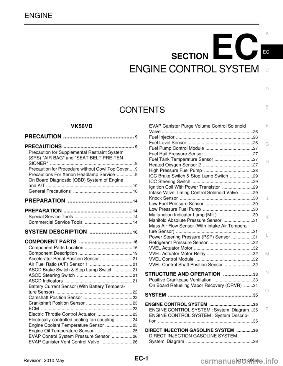
EC-1
ENGINE
C
DE
F
G H
I
J
K L
M
SECTION EC
A
EC
N
O P
CONTENTS
ENGINE CONTROL SYSTEM
VK56VD
PRECAUTION ................ ...............................
9
PRECAUTIONS .............................................. .....9
Precaution for Supplemental Restraint System
(SRS) "AIR BAG" and "SEAT BELT PRE-TEN-
SIONER" ............................................................. ......
9
Precaution for Procedure without Cowl Top Cover ......9
Precautions For Xenon Headlamp Service ...............9
On Board Diagnostic (OBD) System of Engine
and A/T ....................................................................
10
General Precautions ...............................................10
PREPARATION ...........................................14
PREPARATION .............................................. ....14
Special Service Tools .......................................... ....14
Commercial Service Tools ......................................14
SYSTEM DESCRIPTION .............................16
COMPONENT PARTS ................................... ....16
Component Parts Location .................................. ....16
Component Description ...........................................19
Accelerator Pedal Position Sensor ..........................21
Air Fuel Ratio (A/F) Sensor 1 ..................................21
ASCD Brake Switch & Stop Lamp Switch ...............21
ASCD Steering Switch ............................................21
ASCD Indicators ......................................................21
Battery Current Sensor (With Battery Tempera-
ture Sensor) ............................................................
22
Camshaft Position Sensor .......................................22
Crankshaft Position Sensor .....................................23
ECM ........................................................................23
Electric Throttle Control Actuator ............................23
Electrically-controlled cooling fan coupling .............24
Engine Coolant Temperature Sensor ......................25
Engine Oil Temperature Sensor ..............................25
EVAP Control System Pressure Sensor .................26
EVAP Canister Vent Control Valve .........................26
EVAP Canister Purge Volume Control Solenoid
Valve .................................................................... ....
26
Fuel Injector .............................................................26
Fuel Level Sensor ....................................................26
Fuel Pump Control Module ......................................27
Fuel Rail Pressure Sensor .......................................27
Fuel Tank Temperature Sensor ...............................27
Heated Oxygen Sensor 2 ........................................27
High Pressure Fuel Pump .......................................28
ICC Brake Switch & Stop Lamp Switch ...................29
ICC Steering Switch ................................................29
Ignition Coil With Power Transistor .........................29
Intake Valve Timing Control Solenoid Valve ...........29
Knock Sensor ...................................................... ....30
Low Fuel Pressure Sensor ......................................30
Low Pressure Fuel Pump ........................................30
Malfunction Indicator Lamp (MIL) ............................30
Manifold Absolute Pressure Sensor ........................31
Mass Air Flow Sensor (With Intake Air Tempera-
ture Sensor) .............................................................
31
Power Steering Pressure (PSP) Sensor ..................31
Refrigerant Pressure Sensor ............................... ....32
VVEL Actuator Motor ...............................................32
VVEL Actuator Motor Relay .....................................32
VVEL Control Module ..............................................32
VVEL Control Shaft Position Sensor .......................32
STRUCTURE AND OPERATION .....................33
Positive Crankcase Ventilation ................................33
On Board Refueling Vapor Recovery (ORVR) ........34
SYSTEM ............................................................35
ENGINE CONTROL SYSTEM ........................ ...........35
ENGINE CONTROL SYSTEM : System Diagram ....35
ENGINE CONTROL SYSTEM : System Descrip-
tion ...........................................................................
35
DIRECT INJECTION GASOLINE SYSTEM .......... ....36
DIRECT INJECTION GASOLINE SYSTEM :
System Diagram .....................................................
36
Revision: 2010 May2011 QX56
Page 2564 of 5598
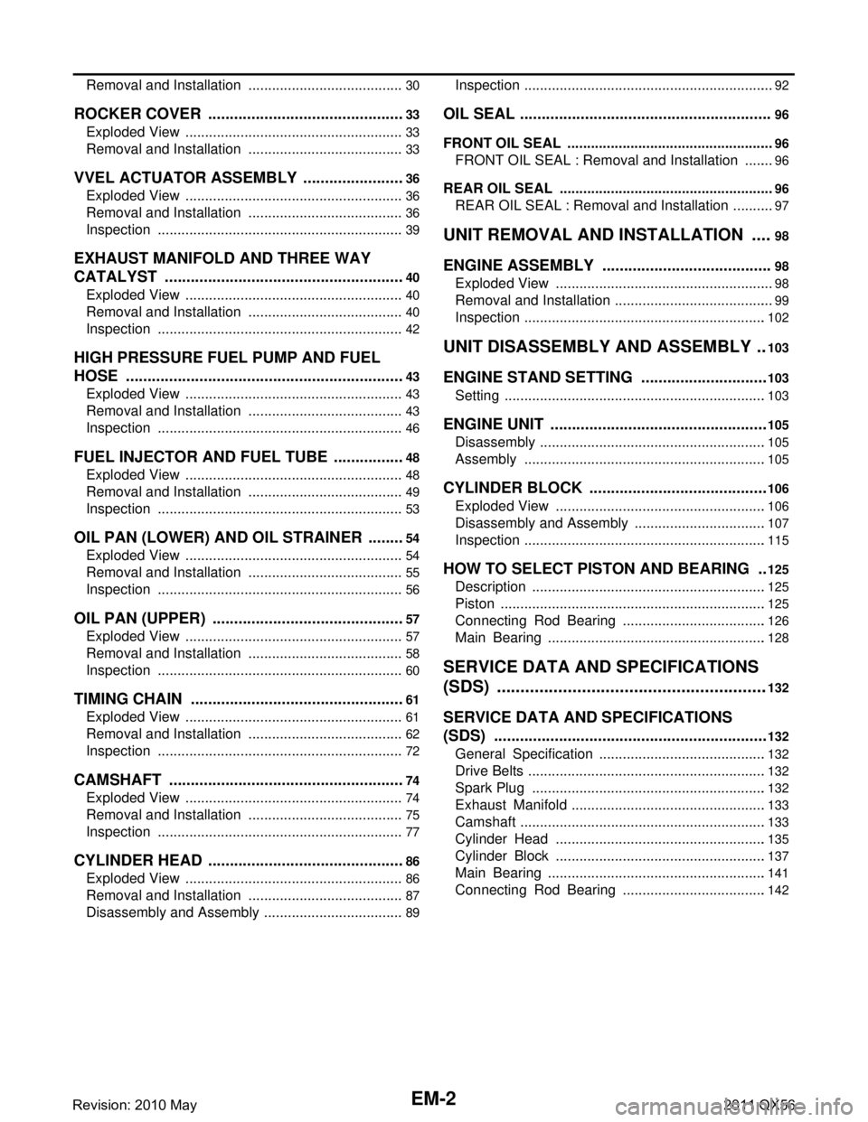
EM-2
Removal and Installation ........................................30
ROCKER COVER ..............................................33
Exploded View ..................................................... ...33
Removal and Installation ........................................33
VVEL ACTUATOR ASSEMBLY ........................36
Exploded View ..................................................... ...36
Removal and Installation ........................................36
Inspection ...............................................................39
EXHAUST MANIFOLD AND THREE WAY
CATALYST ........................................................
40
Exploded View ..................................................... ...40
Removal and Installation ........................................40
Inspection ...............................................................42
HIGH PRESSURE FUEL PUMP AND FUEL
HOSE .................................................................
43
Exploded View ..................................................... ...43
Removal and Installation ........................................43
Inspection ...............................................................46
FUEL INJECTOR AND FUEL TUBE .................48
Exploded View ..................................................... ...48
Removal and Installation ........................................49
Inspection ...............................................................53
OIL PAN (LOWER) AND OIL STRAINER .........54
Exploded View ..................................................... ...54
Removal and Installation ........................................55
Inspection ...............................................................56
OIL PAN (UPPER) .......................................... ...57
Exploded View ..................................................... ...57
Removal and Installation ........................................58
Inspection ...............................................................60
TIMING CHAIN ............................................... ...61
Exploded View ..................................................... ...61
Removal and Installation ........................................62
Inspection ...............................................................72
CAMSHAFT .......................................................74
Exploded View ..................................................... ...74
Removal and Installation ........................................75
Inspection ...............................................................77
CYLINDER HEAD ..............................................86
Exploded View ..................................................... ...86
Removal and Installation ........................................87
Disassembly and Assembly ....................................89
Inspection ............................................................. ...92
OIL SEAL ...........................................................96
FRONT OIL SEAL .................................................. ...96
FRONT OIL SEAL : Removal and Installation ........96
REAR OIL SEAL .................................................... ...96
REAR OIL SEAL : Removal and Installation ...........97
UNIT REMOVAL AND INSTALLATION ....98
ENGINE ASSEMBL Y ..................................... ...98
Exploded View ..................................................... ...98
Removal and Installation .........................................99
Inspection ..............................................................102
UNIT DISASSEMBLY AND ASSEMBLY ..103
ENGINE STAND SETTING ..............................103
Setting .................................................................. .103
ENGINE UNIT ...................................................105
Disassembly ......................................................... .105
Assembly ..............................................................105
CYLINDER BLOCK ..........................................106
Exploded View ..................................................... .106
Disassembly and Assembly ..................................107
Inspection ..............................................................115
HOW TO SELECT PISTON AND BEARING ...125
Description ........................................................... .125
Piston ....................................................................125
Connecting Rod Bearing .....................................126
Main Bearing ........................................................128
SERVICE DATA AND SPECIFICATIONS
(SDS) ........ .................................................
132
SERVICE DATA AND SPECIFICATIONS
(SDS) .............................................................. ..
132
General Specification .......................................... .132
Drive Belts .............................................................132
Spark Plug ............................................................132
Exhaust Manifold ..................................................133
Camshaft ...............................................................133
Cylinder Head ......................................................135
Cylinder Block ......................................................137
Main Bearing ........................................................141
Connecting Rod Bearing .....................................142
Revision: 2010 May2011 QX56
Page 2581 of 5598
NOISE, VIBRATION AND HARSHNESS (NVH) TROUBLESHOOTINGEM-19
< SYMPTOM DIAGNOSIS >
C
DE
F
G H
I
J
K L
M A
EM
NP
O
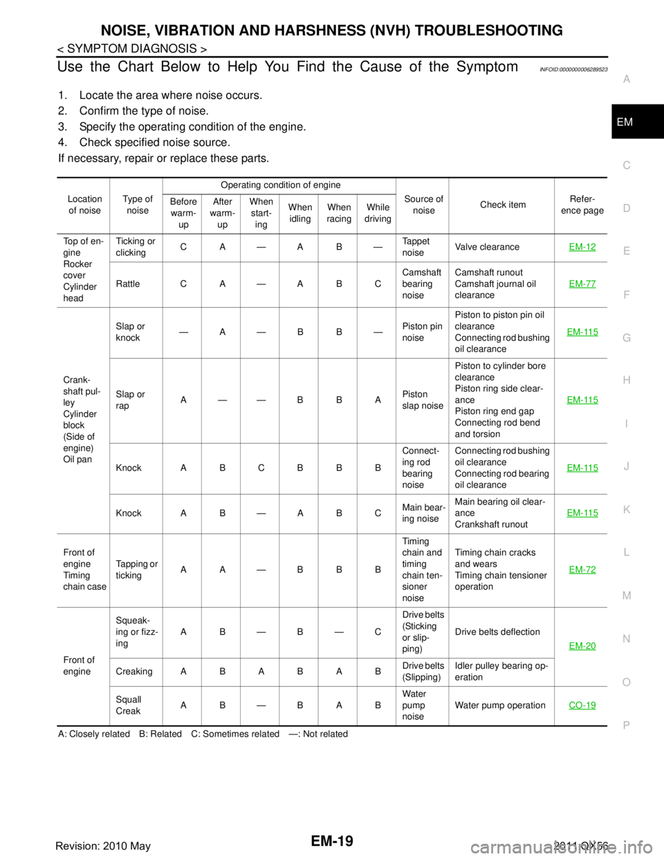
Use the Chart Below to Help You Find the Cause of the SymptomINFOID:0000000006289523
1. Locate the area where noise occurs.
2. Confirm the type of noise.
3. Specify the operating condition of the engine.
4. Check specified noise source.
If necessary, repair or replace these parts.
A: Closely related B: Related C: Sometimes related —: Not related Location
of noise Type of
noise Operating condition of engine
Source of noise Check item Refer-
ence page
Before
warm- up After
warm- up When
start- ing When
idling When
racing While
driving
Top of en-
gine
Rocker
cover
Cylinder
head Ticking or
clicking
CA—AB— Tappet
noiseValve clearance
EM-12
Rattle C A — A B C Camshaft
bearing
noiseCamshaft runout
Camshaft journal oil
clearance
EM-77
Crank-
shaft pul-
ley
Cylinder
block
(Side of
engine)
Oil panSlap or
knock
—A—B B—
Piston pin
noisePiston to piston pin oil
clearance
Connecting rod bushing
oil clearance
EM-115
Slap or
rap
A——B B A
Piston
slap noisePiston to cylinder bore
clearance
Piston ring side clear-
ance
Piston ring end gap
Connecting rod bend
and torsion
EM-115
Knock A B C B B B
Connect-
ing rod
bearing
noiseConnecting rod bushing
oil clearance
Connecting rod bearing
oil clearance
EM-115
Knock A B — A B C
Main bear-
ing noiseMain bearing oil clear-
ance
Crankshaft runout
EM-115
Front of
engine
Timing
chain caseTapping or
ticking
AA—BBB Timing
chain and
timing
chain ten-
sioner
noiseTiming chain cracks
and wears
Timing chain tensioner
operation
EM-72
Front of
engineSqueak-
ing or fizz-
ing
AB—B—C Drive belts
(Sticking
or slip-
ping)Drive belts deflection
EM-20
CreakingABABAB Drive belts
(Slipping)Idler pulley bearing op-
eration
Squall
Creak AB—BAB Water
pump
noiseWater pump operation
CO-19
Revision: 2010 May2011 QX56
Page 2624 of 5598
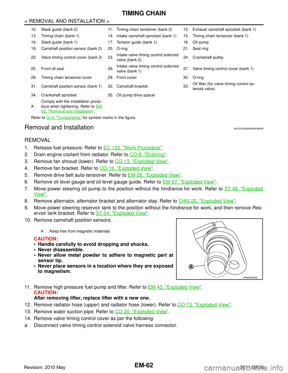
EM-62
< REMOVAL AND INSTALLATION >
TIMING CHAIN
Removal and Installation
INFOID:0000000006289566
REMOVAL
1. Release fuel pressure. Refer to EC-153, "Work Procedure".
2. Drain engine coolant from radiator. Refer to CO-8, "
Draining".
3. Remove fan shroud (lower). Refer to CO-13, "
Exploded View".
4. Remove fan bracket. Refer to CO-16, "
Exploded View".
5. Remove drive belt auto-tensioner. Refer to EM-26, "
Exploded View".
6. Remove oil level gauge and oil level gauge guide. Refer to EM-57, "
Exploded View".
7. Move power steering oil pump to the posit ion without the hindrance for work. Refer to ST-48, "
Exploded
View".
8. Remove alternator, alternator bracket and alternator stay. Refer to CHG-25, "
Exploded View".
9. Move power steering reservoir tank to the position without the hindrance for work, and then remove Res- ervoir tank bracket. Refer to ST-54, "
Exploded View".
10. Remove camshaft position sensors.
CAUTION:
Handle carefully to avoid dropping and shocks.
Never disassemble.
Never allow metal powder to adhere to magnetic part atsensor tip.
Never place sensors in a lo cation where they are exposed
to magnetism.
11. Remove high pressure fuel pump and lifter. Refer to EM-43, "
Exploded View".
CAUTION:
After removing lifter, replace lifter with a new one.
12. Remove radiator hose (upper) and radiator hose (lower). Refer to CO-13, "
Exploded View".
13. Remove water suction pipe. Refer to CO-20, "
Exploded View".
14. Remove valve timing control cover as per the following:
a. Disconnect valve timing control solenoid valve harness connector.
10. Slack guide (bank 2) 11. Timing chain tensioner (bank 2) 12. Exhaust camshaft sprocket (bank 1)
13. Timing chain (bank 1) 14. Intake camshaft sprocket (bank 1) 15. Timing chain tensioner (bank 1)
16. Slack guide (bank 1) 17. Tension guide (bank 1) 18. Oil pump
19. Camshaft position sensor (bank 2) 20. O-ring 21. Seal ring
22. Valve timing control cover (bank 2) 23. Intake valve timing control solenoid
valve (bank 2)24. Crankshaft pulley
25. Front oil seal 26. Intake valve timing control solenoid
valve (bank 1)27. Valve timing control cover (bank 1)
28. Timing chain tensioner cover 29. Front cover 30. O-ring
31. Camshaft position sensor (bank 1) 32. Camshaft bracket 33. Oil filter (for valve timing control so-
lenoid valve)
34. Crankshaft sprocket 35. Oil pump drive spacer
A. Comply with the installation proce-
dure when tightening. Refer to
EM-
62, "Removal and Installation".
Refer to GI-4, "
Components" for symbol marks in the figure.
A : Keep free from magnetic materials
JPBIA0454ZZ
Revision: 2010 May2011 QX56
Page 2625 of 5598
TIMING CHAINEM-63
< REMOVAL AND INSTALLATION >
C
DE
F
G H
I
J
K L
M A
EM
NP
O
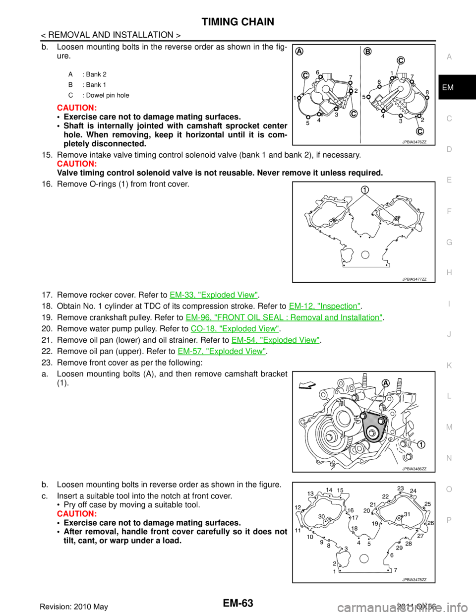
b. Loosen mounting bolts in the reverse order as shown in the fig-
ure.
CAUTION:
Exercise care not to damage mating surfaces.
Shaft is internally jointed with camshaft sprocket center
hole. When removing, keep it horizontal until it is com-
pletely disconnected.
15. Remove intake valve timing control solenoid valve (bank 1 and bank 2), if necessary. CAUTION:
Valve timing control solenoid valve is no t reusable. Never remove it unless required.
16. Remove O-rings (1) from front cover.
17. Remove rocker cover. Refer to EM-33, "
Exploded View".
18. Obtain No. 1 cylinder at TDC of its compression stroke. Refer to EM-12, "
Inspection".
19. Remove crankshaft pulley. Refer to EM-96, "
FRONT OIL SEAL : Removal and Installation".
20. Remove water pump pulley. Refer to CO-18, "
Exploded View".
21. Remove oil pan (lower) and oil strainer. Refer to EM-54, "
Exploded View".
22. Remove oil pan (upper). Refer to EM-57, "
Exploded View".
23. Remove front cover as per the following:
a. Loosen mounting bolts (A), and then remove camshaft bracket (1).
b. Loosen mounting bolts in reverse order as shown in the figure.
c. Insert a suitable tool into the notch at front cover. Pry off case by moving a suitable tool.
CAUTION:
Exercise care not to damage mating surfaces.
After removal, handle front cover carefully so it does not
tilt, cant, or warp under a load.
A: Bank 2
B: Bank 1
C : Dowel pin hole
JPBIA3476ZZ
JPBIA3477ZZ
JPBIA3486ZZ
JPBIA3478ZZ
Revision: 2010 May2011 QX56
Page 2626 of 5598
EM-64
< REMOVAL AND INSTALLATION >
TIMING CHAIN
24. Remove oil pump and oil pump drive spacer.
25. Remove front oil seal from front cover using suitable tool. Use screwdriver for removal.
CAUTION:
Be careful not to damage front cover.
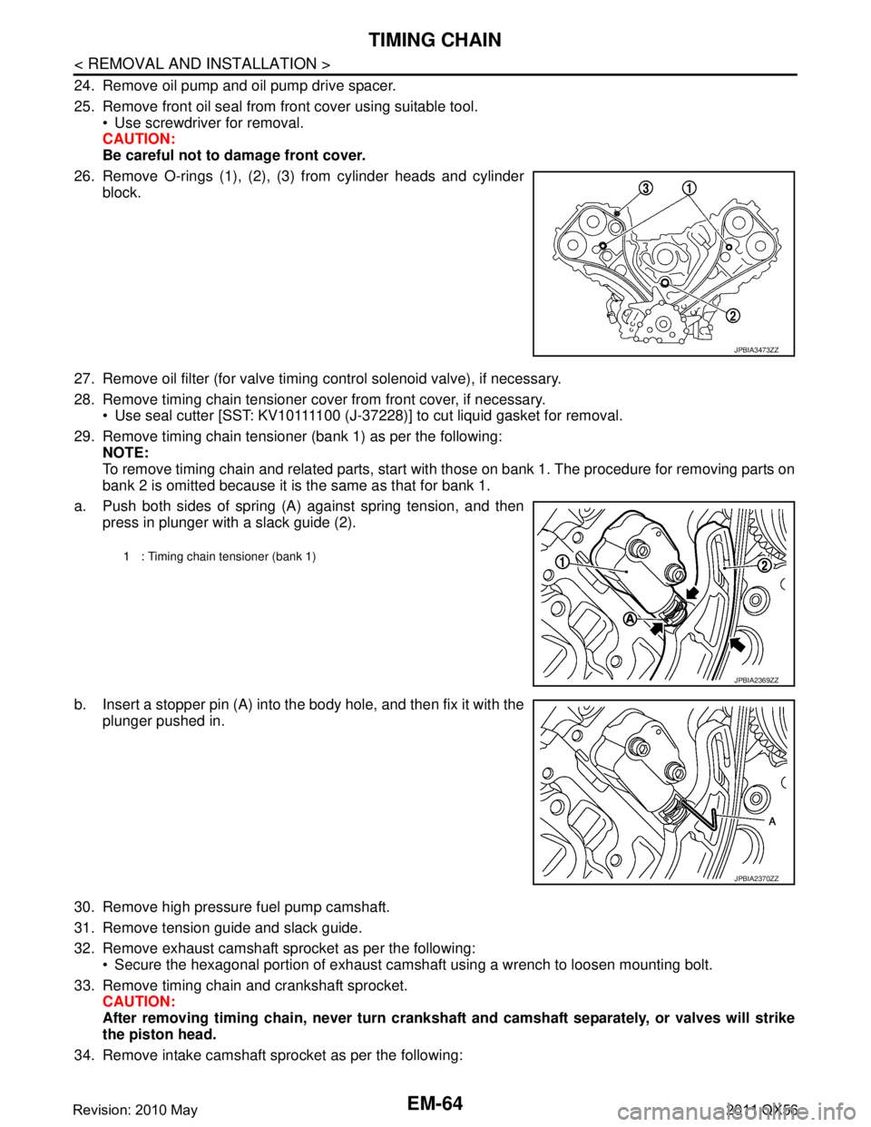
26. Remove O-rings (1), (2), (3) from cylinder heads and cylinder block.
27. Remove oil filter (for valve timing control solenoid valve), if necessary.
28. Remove timing chain tensioner cover from front cover, if necessary. Use seal cutter [SST: KV10111100 (J-37228)] to cut liquid gasket for removal.
29. Remove timing chain tensioner (bank 1) as per the following: NOTE:
To remove timing chain and related parts, start with those on bank 1. The procedure for removing parts on
bank 2 is omitted because it is the same as that for bank 1.
a. Push both sides of spring (A) against spring tension, and then press in plunger with a slack guide (2).
b. Insert a stopper pin (A) into the body hole, and then fix it with the
plunger pushed in.
30. Remove high pressure fuel pump camshaft.
31. Remove tension guide and slack guide.
32. Remove exhaust camshaft sprocket as per the following: Secure the hexagonal portion of exhaust camshaf t using a wrench to loosen mounting bolt.
33. Remove timing chain and crankshaft sprocket. CAUTION:
After removing timing chain, never turn cranksh aft and camshaft separately, or valves will strike
the piston head.
34. Remove intake camshaft sprocket as per the following:
JPBIA3473ZZ
1 : Timing chain tensioner (bank 1)
JPBIA2369ZZ
JPBIA2370ZZ
Revision: 2010 May2011 QX56
Page 2627 of 5598
TIMING CHAINEM-65
< REMOVAL AND INSTALLATION >
C
DE
F
G H
I
J
K L
M A
EM
NP
O
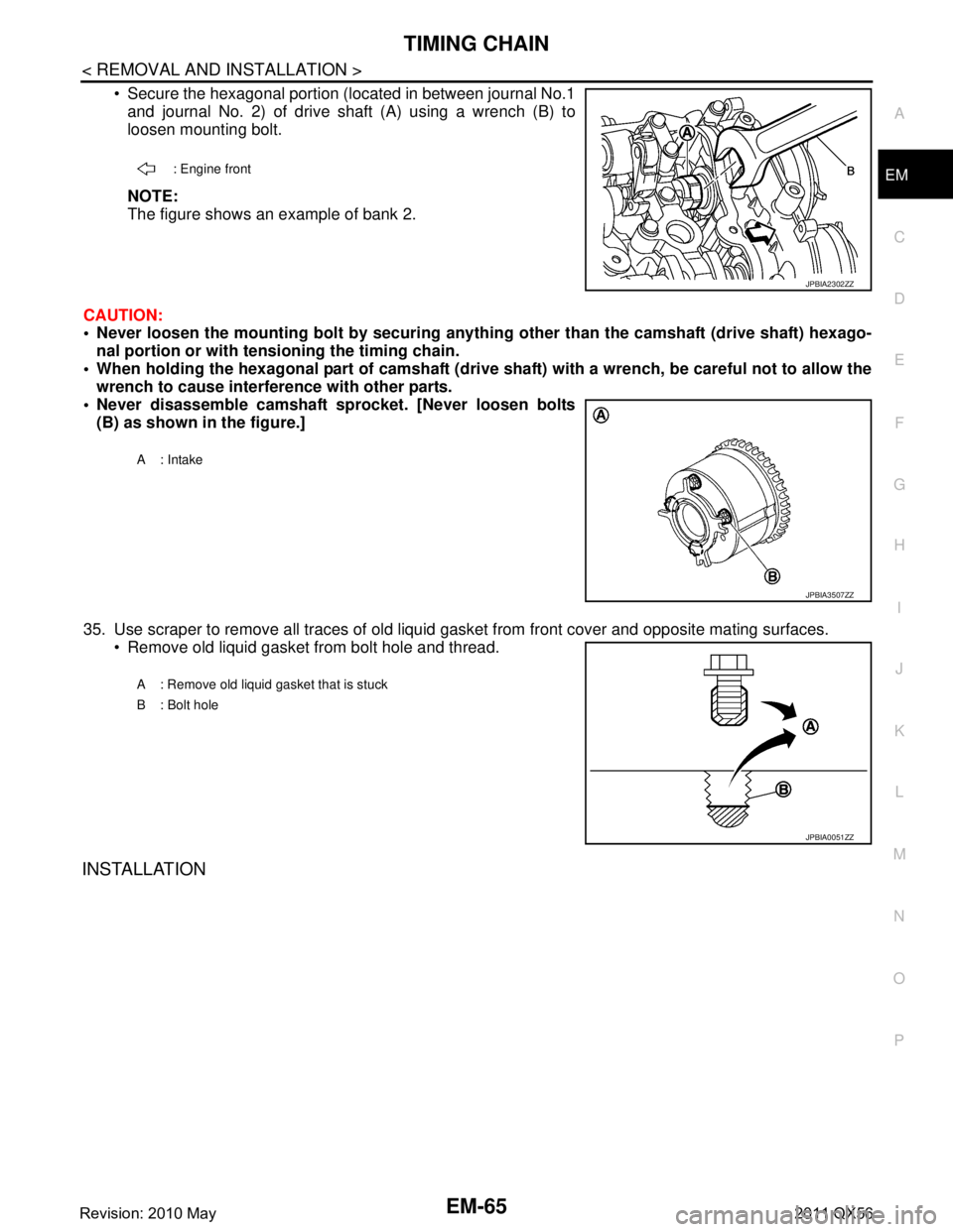
Secure the hexagonal portion (located in between journal No.1
and journal No. 2) of drive shaft (A) using a wrench (B) to
loosen mounting bolt.
NOTE:
The figure shows an example of bank 2.
CAUTION:
Never loosen the mounting bolt by securing anyt hing other than the camshaft (drive shaft) hexago-
nal portion or with tensioning the timing chain.
When holding the hexagonal part of camshaft (drive shaft) with a wrench, be careful not to allow the
wrench to cause interference with other parts.
Never disassemble camshaft sprocket. [Never loosen bolts (B) as shown in the figure.]
35. Use scraper to remove all traces of old liquid gasket from front cover and opposite mating surfaces. Remove old liquid gasket from bolt hole and thread.
INSTALLATION
: Engine front
JPBIA2302ZZ
A: Intake
JPBIA3507ZZ
A : Remove old liquid gasket that is stuck
B : Bolt hole
JPBIA0051ZZ
Revision: 2010 May2011 QX56