Page 2980 of 5598
GI-16
< HOW TO USE THIS MANUAL >
ABBREVIATIONS
I
K
L
M
N
O
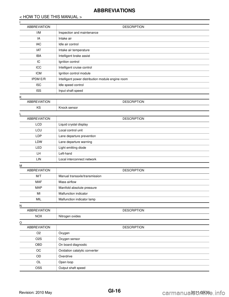
ABBREVIATION DESCRIPTIONI/M Inspection and maintenanceIA Intake air
IAC Idle air control IAT Intake air temperature
IBA Intelligent brake assist IC Ignition control
ICC Intelligent cruise control
ICM Ignition control module
IPDM E/R Intelligent power distribution module engine room ISC Idle speed controlISS Input shaft speed
ABBREVIATION DESCRIPTION KS Knock sensor
ABBREVIATION DESCRIPTION LCD Liquid crystal display
LCU Local control unitLDP Lane departure prevention
LDW Lane departure warning LED Light emitting diode LH Left-hand
LIN Local interconnect network
ABBREVIATION DESCRIPTION M/T Manual transaxle/transmission
MAF Mass airflow
MAP Manifold absolute pressure MI Malfunction indicator
MIL Malfunction indicator lamp
ABBREVIATION DESCRIPTION NOX Nitrogen oxides
ABBREVIATION DESCRIPTION O2 Oxygen
O2S Oxygen sensor
OBD On board diagnostic OC Oxidation catalytic converter
OD OverdriveOL Open loop
OSS Output shaft speed
Revision: 2010 May2011 QX56
Page 3271 of 5598
INL-4
< SYSTEM DESCRIPTION >
COMPONENT PARTS
SYSTEM DESCRIPTION
COMPONENT PARTS
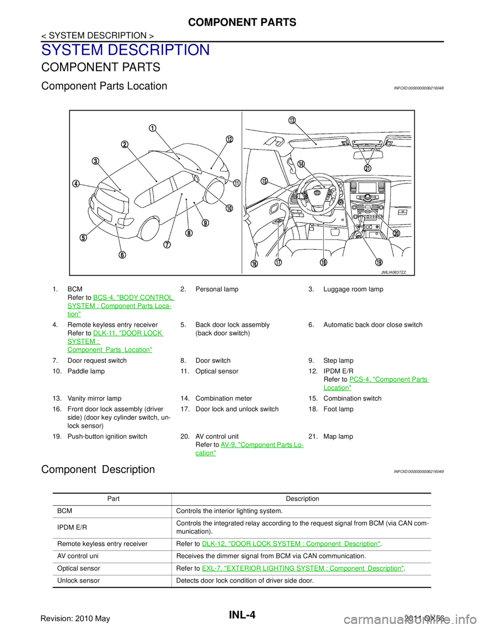
Component Parts LocationINFOID:0000000006216048
Component DescriptionINFOID:0000000006216049
1. BCMRefer to BCS-4, "
BODY CONTROL
SYSTEM : Componen t Parts Loca-
tion"
2. Personal lamp 3. Luggage room lamp
4. Remote keyless entry receiver Refer to DLK-11, "
DOOR LOCK
SYSTEM :
ComponentPartsLocation"
5. Back door lock assembly
(back door switch) 6. Automatic back door close switch
7. Door request switch 8. Door switch 9. Step lamp
10. Paddle lamp 11. Optical sensor 12. IPDM E/R Refer to PCS-4, "
Component Parts
Location"
13. Vanity mirror lamp 14. Combination meter 15. Combination switch
16. Front door lock assembly (driver
side) (door key cylinder switch, un-
lock sensor) 17. Door lock and unlock switch 18. Foot lamp
19. Push-button ignition switch 20. AV control unit Refer to AV- 9 , "
Component Parts Lo-
cation"
21. Map lamp
JMLIA0837ZZ
Part Description
BCM Controls the interior lighting system.
IPDM E/R Controls the integrated relay according to the request signal from BCM (via CAN com-
munication).
Remote keyless entry receiver Refer to DLK-12, "
DOOR LOCK SYSTEM : ComponentDescription".
AV control uni Receives the dimmer signal from BCM via CAN communication.
Optical sensor Refer to EXL-7, "
EXTERIOR LIGHTING SYSTEM : ComponentDescription".
Unlock sensor Detects door lock condition of driver side door.
Revision: 2010 May2011 QX56
Page 3282 of 5598
DIAGNOSIS SYSTEM (BCM)INL-15
< SYSTEM DESCRIPTION >
C
DE
F
G H
I
J
K
M A
B
INL
N
O P
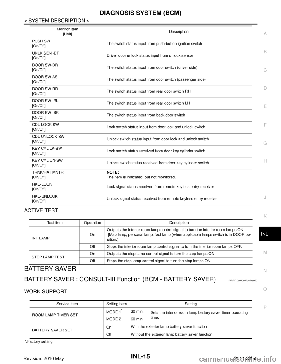
ACTIVE TEST
BATTERY SAVER
BATTERY SAVER : CONSULT-III Function (BCM - BATTERY SAVER)INFOID:0000000006216060
WORK SUPPORT
*:Factory setting PUSH SW
[On/Off]
The switch status input from push-button ignition switch
UNLK SEN -DR
[On/Off] Driver door unlock status input from unlock sensor
DOOR SW-DR
[On/Off] The switch status input from door switch (driver side)
DOOR SW-AS
[On/Off] The switch status input from door switch (passenger side)
DOOR SW-RR
[On/Off] The switch status input from rear door switch RH
DOOR SW- RL
[On/Off] The switch status input from rear door switch LH
DOOR SW- BK
[On/Off] The switch status input from back door switch
CDL LOCK SW
[On/Off] Lock switch status input from door lock and unlock switch
CDL UNLOCK SW
[On/Off] Unlock switch status input from door lock and unlock switch
KEY CYL LK-SW
[On/Off] Lock switch status received from door key cylinder switch
KEY CYL UN-SW
[On/Off] Unlock switch status received from door key cylinder switch
TRNK/HAT MNTR
[On/Off] NOTE:
The item is indicated, but not monitored.
RKE-LOCK
[On/Off] Lock signal status received from remote keyless entry receiver
RKE-UNLOCK
[On/Off] Unlock signal status received from remote keyless entry receiver
Monitor item
[Unit] Description
Test item Operation Description
INT LAMP OnOutputs the interior room lamp control signal to turn the interior room lamps ON.
[Map lamp, personal lamp, foot lamp (when applicable lamps switch is in DOOR po-
sition.)]
Off Stops the interior room lamp control signal to turn the interior room lamps OFF.
STEP LAMP TEST On Outputs the step lamp control signal to turn the step lamps ON.
Off Stops the step lamp control signal to turn the step lamps ON.
Service item Setting item Setting
ROOM LAMP TIMER SET MODE 1
*30 min.
Sets the interior room lamp battery saver timer operating
time.
MODE 2 60 min.
BATTERY SAVER SET On
*With the exterior lamp battery saver function
Off Without the exterior lamp battery saver function
Revision: 2010 May2011 QX56
Page 3378 of 5598
HEADLININGINT-29
< REMOVAL AND INSTALLATION >
C
DE
F
G H
I
K L
M A
B
INT
N
O P
Removal and InstallationINFOID:0000000006220257
REMOVAL
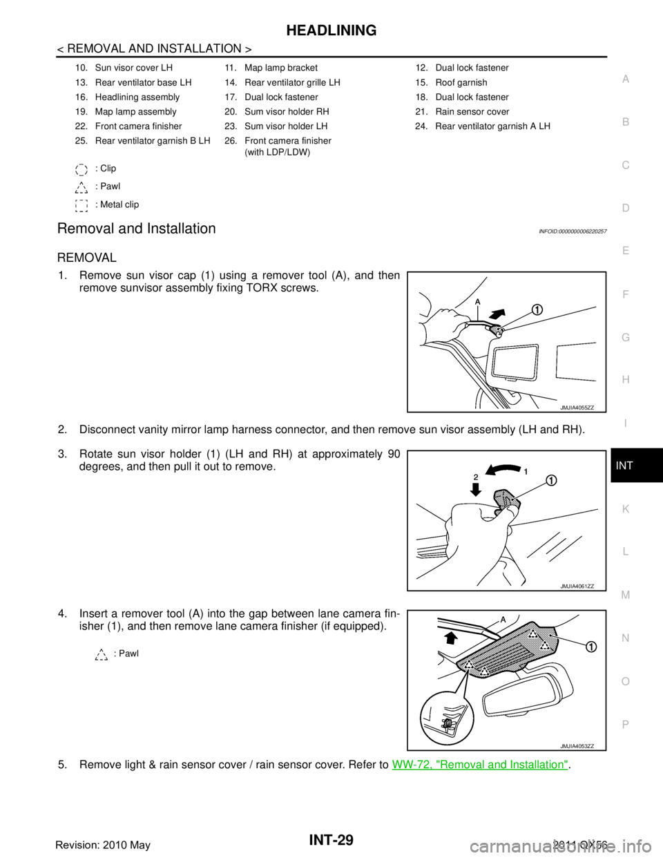
1. Remove sun visor cap (1) using a remover tool (A), and then remove sunvisor assembly fixing TORX screws.
2. Disconnect vanity mirror lamp harness connector, and then remove sun visor assembly (LH and RH).
3. Rotate sun visor holder (1) (LH and RH) at approximately 90 degrees, and then pull it out to remove.
4. Insert a remover tool (A) into the gap between lane camera fin- isher (1), and then remove lane camera finisher (if equipped).
5. Remove light & rain sensor cover / rain sensor cover. Refer to WW-72, "
Removal and Installation".
10. Sun visor cover LH 11. Map lamp bracket 12. Dual lock fastener
13. Rear ventilator base LH 14. Rear ventilator grille LH 15. Roof garnish
16. Headlining assembly 17. Dual lock fastener 18. Dual lock fastener
19. Map lamp assembly 20. Sum visor holder RH 21. Rain sensor cover
22. Front camera finisher 23. Sum visor holder LH 24. Rear ventilator garnish A LH
25. Rear ventilator garnish B LH 26. Front camera finisher
(with LDP/LDW)
: Clip
: Pawl
: Metal clip
JMJIA4055ZZ
JMJIA4061ZZ
: Pawl
JMJIA4053ZZ
Revision: 2010 May2011 QX56