2011 INFINITI QX56 front alignment
[x] Cancel search: front alignmentPage 4 of 5598

QUICK REFERENCE CHART QX56
FRONT WHEEL ALIGNMENT
ELS0003X
*1: The minimum value and maximum value is the same as the nominal value.
Measure value under unladen*2 conditions.
*2: Fuel, engine coolant and lubricant are full. Spare tire, jack, hand tools and mats are in designated positions.
REAR WHEEL ALIGNMENTELS0003Y
Measure value under unladen* conditions.
*: Fuel, engine coolant and lubricant are full. Spare tire, jack, hand tools and mats are in designated positions. Item Standard
Measurement wheel Left side Right side
Camber
Degree minute (Decimal degree) Minimum
−0 °45 ′ ( −0.75 °) −0°55 ′ ( −0.91 °)
Nominal 0 ° 00 ′ (0.00 °) −0°10 ′ ( −0.17 °)
Maximum 0 ° 45 ′ (0.75 °)0 ° 35 ′ (0.58 °)
Left and right difference 0 ° 33 ′ (0.55 °) or less
Caster
Degree minute (Decimal degree) Minimum 2
° 20 ′ (2.34 °)2 ° 40 ′ (2.67 °)
Nominal 3 ° 05 ′ (3.08 °)3 ° 25 ′ (3.42 °)
Maximum 3 ° 50 ′ (3.83 °)4 ° 10 ′
(4.16 °)
Left and right difference 0 ° 45 ′ (0.75 °) or less
Kingpin inclination
Degree minute (Decimal degree) Minimum — —
Nominal
13° 20 ′ (13.33 °)
*113 ° 25 ′ (13.42 °)*1
Maximum — —
Toe-in Total toe-in
Distance
Minimum In 1.4 mm (0.055 in)
Nominal In 2.4 mm (0.094 in)
Maximum In 3.4 mm (0.134 in)
Toe angle (left wheel or right wheel)
Degree minute (Decimal degree) Minimum In 0
° 03 ′ (0.05 °)
Nominal In 0 ° 05 ′ (0.08 °)
Maximum In 0 ° 07 ′ (0.11 °)
Item Standard
Camber
Degree minute (Decimal degree) Minimum –1
° 00 ′ (–1.00 °)
Nominal –0 ° 30 ′ (–0.50 °)
Maximum 0 ° 00 ′ (0.00 °)
Left and right difference 0 ° 45 ′ (0.75 °) or less
To e - i n Total toe-in
Distance
Minimum 0 mm (0 in)
Nominal In 3.4 mm (0.134 in)
Maximum In 6.8 mm (0.268 in)
Toe angle (left wheel or right wheel)
Degree minute (Decimal degree) Minimum 0
° 00 ′ (0.00 °)
Nominal In 0 ° 07 ′ (0.12 °)
Maximum In 0 ° 14 ′ (0.23 °)
2011
Page 581 of 5598
![INFINITI QX56 2011 Factory Service Manual
BRC-64
< BASIC INSPECTION >[WITH VDC]
ADJUSTMENT OF STEERING ANGLE
SENSOR NEUTRAL POSITION
ADJUSTMENT OF STEERING ANGLE SENSOR NEUTRAL POSITION
DescriptionINFOID:0000000006222588
Always adjust the n](/manual-img/42/57033/w960_57033-580.png "INFINITI QX56 2011 Factory Service Manual
BRC-64
< BASIC INSPECTION >[WITH VDC]
ADJUSTMENT OF STEERING ANGLE
SENSOR NEUTRAL POSITION
ADJUSTMENT OF STEERING ANGLE SENSOR NEUTRAL POSITION
DescriptionINFOID:0000000006222588
Always adjust the n")
BRC-64
< BASIC INSPECTION >[WITH VDC]
ADJUSTMENT OF STEERING ANGLE
SENSOR NEUTRAL POSITION
ADJUSTMENT OF STEERING ANGLE SENSOR NEUTRAL POSITION
DescriptionINFOID:0000000006222588
Always adjust the neutral position of steering angle sensor before driving when the following operation is per-
formed.
× : Required —: Not required
Work ProcedureINFOID:0000000006222589
ADJUST THE NEUTRAL POSITION OF STEERING ANGLE SENSOR
CAUTION:
Always use CONSULT-III when adju sting the neutral position of steering angle sensor. (It cannot be
adjusted other than with CONSULT-III.)
1.CHECK THE VEHICLE STATUS
Stop vehicle with front wheels in the straight-ahead position.
Does the vehicle stay in the straight-ahead position?
YES >> GO TO 2.
NO >> Steer the steering wheel to the st raight-ahead position. Stop the vehicle.
2.ADJUST NEUTRAL POSITION OF STEERING ANGLE SENSOR
With CONSULT-III.
1. Turn the ignition switch ON.
CAUTION:
Never start engine.
2. Select “ABS”, “WORK SUPPORT” and “ST AN GLE SENSOR ADJUSTMENT” in this order.
3. Select “START”. CAUTION:
Never touch steering wheel while adjusting steering angle sensor.
4. After approx. 10 seconds, select “END”.
5. Turn ignition switch OFF and then turn it ON again. CAUTION:
Be sure to perform the operation above.
>> GO TO 3.
3.CHECK DATA MONITOR
With CONSULT-III.
1. The vehicle is either pointing straight ahead or t he vehicle needs to be moved. Stop when it is pointing
straight ahead.
Procedure Adjust the neutral position of steering angle sensor
Removing/ installing ABS actuator and electric unit (control unit) —
Replacing ABS actuator and electric unit (control unit) —
Removing/installing steering angle sensor ×
Replacing steering angle sensor ×
Removing/installing steering components ×
Replacing steering components ×
Removing/installing suspension components ×
Replacing suspension components ×
Removing/installing tire —
Replacing tire —
Tire rotation —
Adjusting wheel alignment. ×
Revision: 2010 May2011 QX56
Page 676 of 5598

BRM-1
BODY EXTERIOR, DOORS, ROOF & VEHICLE SECURITY
C
D
E
F
G H
I
J
L
M
SECTION BRM
A
B
BRM
N
O P
CONTENTS
BODY REPAIR
VEHICLE INFORMATION ... ..........................2
BODY EXTERIOR PAINT COLOR ................ .....2
Body Exterior Paint Color ................................. ......2
PRECAUTION ...............................................4
REPAIRING HIGH STRENGTH STEEL ......... .....4
High Strength Steel (HSS) ................................ ......4
Handling of Ultra High Strength Steel Plate Parts ......6
PREPARATION ............................................7
REPAIRING MATERIAL ................................ .....7
Foam Repair ....................................................... ......7
BODY COMPONENT PARTS .............................9
Underbody Component Parts ............................ ......9
Body Component Parts ...........................................11
Frame Component Parts .........................................13
REMOVAL AND INSTALLATION ...............15
CORROSION PROTECTION ......................... ....15
Description .......................................................... ....15
Anti-corrosive Wax ..................................................15
Undercoating ...........................................................16
Stone Guard Coat ...................................................17
Body Sealing ...........................................................18
BODY CONSTRUCTION ....................................22
Body Construction ............................................... ....22
REPLACEMENT OPERATIONS .......................24
Description ...............................................................24
Radiator Core Support .............................................26
Hoodledge ...............................................................26
Hoodledge (Partial Replacement) ...........................27
Front Pillar ...............................................................29
Center Pillar .............................................................32
Outer Sill .................................................................35
Rear Fender ............................................................39
Rear Fender Extension ............................................42
Rear Panel and Rear End Crossmember ................42
Rear Floor Rear .....................................................45
Crush Horn ..............................................................46
SERVICE DATA AND SPECIFICATIONS
(SDS) ............... .............................................
48
BODY ALIGNMENT ..........................................48
Body Center Marks ............................................ ....48
Description ...............................................................48
Engine Compartment ..............................................49
Underbody ...............................................................52
Passenger Compartment .........................................54
Rear Body ...............................................................56
LOCATION OF PLASTIC PARTS ....................58
Precautions for Plastics ...........................................58
Location of Plastic Parts ..........................................59
Revision: 2010 May2011 QX56
Page 723 of 5598

BRM-48
< SERVICE DATA AND SPECIFICATIONS (SDS)
BODY ALIGNMENT
SERVICE DATA AND SPECIFICATIONS (SDS)
BODY ALIGNMENT
Body Center MarksINFOID:0000000006248507
A mark is placed on each part of the body to indicate the vehicle center. When repairing the vehicle frame
(members, pillars, etc.) damaged by an accident which it enables more accurate and effective repair by using
these marks together with body alignment specifications.
Unit: mm (in)
DescriptionINFOID:0000000006248508
All dimensions indicated in the figures are actual.
When using a tracking gauge, adjust both pointers to equal length. Then check the pointers and gauge itself
to make sure there is no free play.
: Vehicle front
Points Portion Marks
A Upper dash Hole 7 ×12 (0.28 ×0.47)
B Cowl top Embossment
C Rear roof Indent
JSKIA1895ZZ
Revision: 2010 May2011 QX56
Page 724 of 5598

BODY ALIGNMENTBRM-49
< SERVICE DATA AND SPECIFICATIONS (SDS)
C
DE
F
G H
I
J
L
M A
B
BRM
N
O P
When a measuring tape is used, check to be su re there is no elongation, twisting or bending.
Measurements should be taken at the center of the mounting holes.
An asterisk (*) following the value at the measuring poi nt indicates that the measuring point on the other side
is symmetrically the same value.
The coordinates of the measurement points are the distances measured from the standard line of ″X ″, ″Y ″
and ″Z ″.
″Z ″: Imaginary base line [300 mm (11.81 in) below datum line ( ″0Z ″ at design plan)]
Engine CompartmentINFOID:0000000006248509
Measurement
Dimensions marked with ″*″ indicate symmetrically identical dimensions on both the right and left hand of the
vehicle.
1. Vehicle center 2. Front axle center 3. Imaginary base line
JSKIA0073GB
Revision: 2010 May2011 QX56
Page 726 of 5598

BODY ALIGNMENTBRM-51
< SERVICE DATA AND SPECIFICATIONS (SDS)
C
DE
F
G H
I
J
L
M A
B
BRM
N
O P
Unit: mm (in)
: Vehicle front
JSKIA1947ZZ
Point Material Point Material
A Upper dash flange end of center positioning mark E, e Lower hoodledge hole center φ8 (0.31)
B, b Hood hinge installing hole center φ11 (0.43) G, g, J, j Hoodledge connector bracket hole center
G, g: 14
×12 (0.55 ×0.47)
J, j: φ12 (0.47)
C, c, F, f Hoodledge reinforcement hole center
C, c:
φ8 (0.31)
F, f: φ12 (0.47) K, k, M, m, N,
n, O, oUpper radiator core support hole center
K, k:
φ8 (0.31)
M, m: φ12 (0.47)
N, n, O, o: φ11 ( 0 . 4 3 )
D, d, H, h Front fender installing hole center φ7 (0.28) P, p, Q, q Lower outer radiator core connector hole center
φ
7 (0.28)
Revision: 2010 May2011 QX56
Page 728 of 5598
BODY ALIGNMENTBRM-53
< SERVICE DATA AND SPECIFICATIONS (SDS)
C
DE
F
G H
I
J
L
M A
B
BRM
N
O P
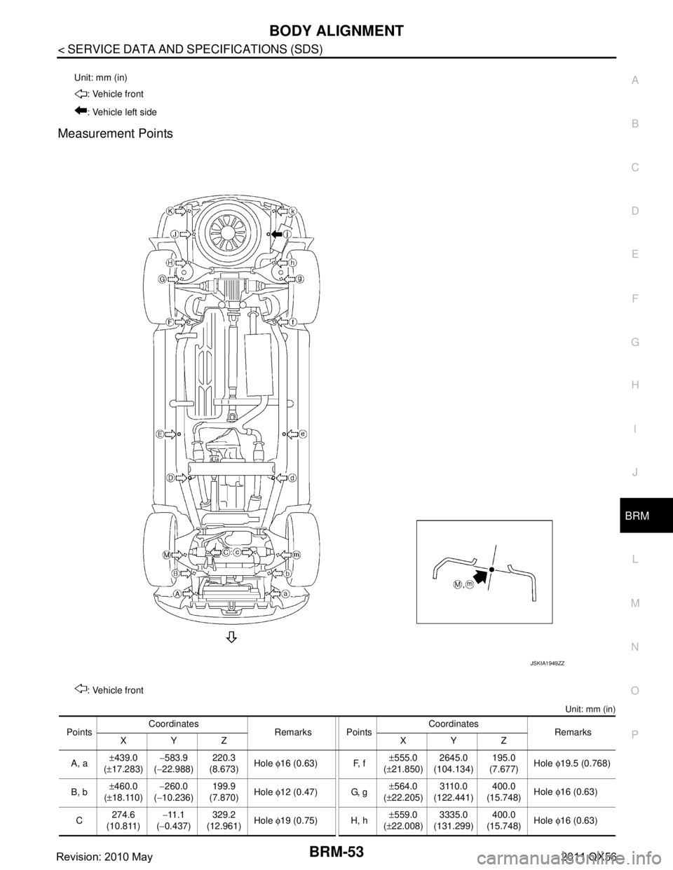
Measurement Points
Unit: mm (in)
Unit: mm (in) : Vehicle front
: Vehicle left side
: Vehicle front
Points Coordinates
Remarks Points Coordinates
Remarks
XYZ XYZ
A, a ±
439.0
( ± 17.283) −
583.9
( − 22.988) 220.3
(8.673) Hole
φ16 (0.63) F, f ±
555.0
( ± 21.850) 2645.0
(104.134) 195.0
(7.677) Hole
φ19.5 (0.768)
B, b ±
460.0
( ± 18.110) −
260.0
( − 10.236) 199.9
(7.870) Hole
φ12 (0.47) G, g ±
564.0
( ± 22.205) 3110.0
(122.441) 400.0
(15.748) Hole
φ16 (0.63)
C 274.6
(10.811) −
11 . 1
( − 0.437) 329.2
(12.961) Hole
φ19 (0.75) H, h ±
559.0
( ± 22.008) 3335.0
(131.299) 400.0
(15.748) Hole
φ16 (0.63)
JSKIA1949ZZ
Revision: 2010 May2011 QX56
Page 731 of 5598

BRM-56
< SERVICE DATA AND SPECIFICATIONS (SDS)
BODY ALIGNMENT
Unit: mm (in)
Rear BodyINFOID:0000000006248512
Measurement
Dimensions marked with ″*″ indicate symmetrically identical dimensions on both the right and left hand of the
vehicle.
Measurement Points
: Vehicle front
Point Material Point Material
A Cowl top positioning mark of center positioning
mark H, h, J, j, K, k,
M, m
Center pillar indent
B, b Roof indent O, o, P, p Rear fender indent
C, c Front pillar joggle Q, q Parking brake bracket hole center φ13 (0.51)
D, d, E, e, N, n Outer side body indent R, r 2nd seat mounting front crossmember hole cen-
ter
φ7 (0.28)
F, f, G, g Front pillar indent S, s, T, t, U, u,
V, vDoor hinge installing hole center
S, s, U, u:
φ9 (0.35)
T, t, V, v: φ12 (0.47)
Unit: mm (in)
JSKIA1902GB
Revision: 2010 May2011 QX56