2011 INFINITI QX56 steering wheel
[x] Cancel search: steering wheelPage 2950 of 5598
FSU-8
< PERIODIC MAINTENANCE >
WHEEL ALIGNMENT
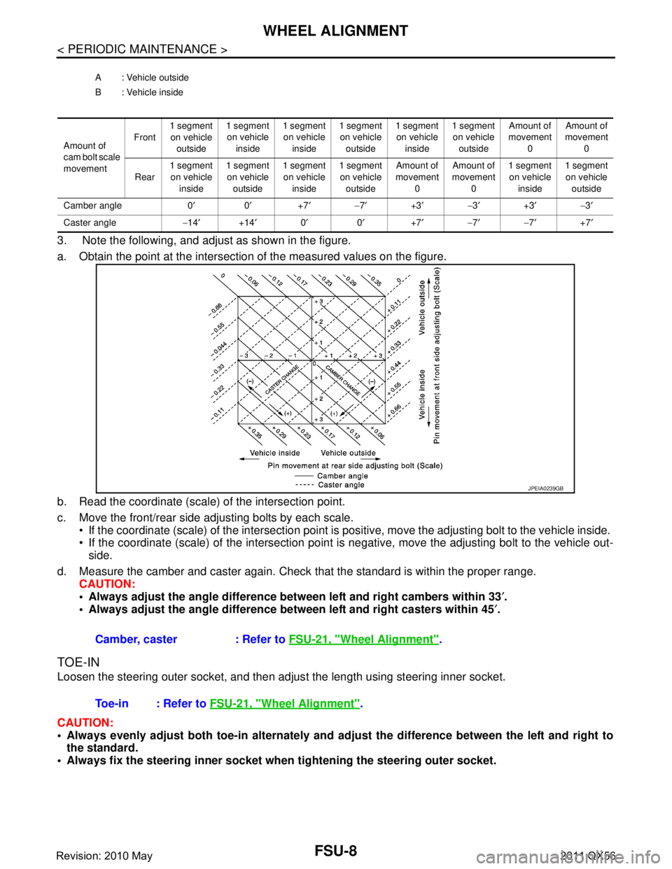
3. Note the following, and adjust as shown in the figure.
a. Obtain the point at the intersection of the measured values on the figure.
b. Read the coordinate (scale) of the intersection point.
c. Move the front/rear side adjusting bolts by each scale. If the coordinate (scale) of the intersection point is positive, move the adjusting bolt to the vehicle inside.
If the coordinate (scale) of the intersection point is negative, move the adjusting bolt to the vehicle out-
side.
d. Measure the camber and caster again. Check that the standard is within the proper range.
CAUTION:
Always adjust the angle difference betw een left and right cambers within 33′.
Always adjust the angle difference be tween left and right casters within 45′.
TOE-IN
Loosen the steering outer socket, and then adjus t the length using steering inner socket.
CAUTION:
Always evenly adjust both toe-in alternately and adjust the difference between the left and right to
the standard.
Always fix the steering inner socket when tightening the steering outer socket.
A : Vehicle outside
B : Vehicle inside
Amount of
cam bolt scale
movement Front
1 segment
on vehicle outside 1 segment
on vehicle inside 1 segment
on vehicle inside 1 segment
on vehicle outside 1 segment
on vehicle inside 1 segment
on vehicle outside Amount of
movement 0 Amount of
movement 0
Rear 1 segment
on vehicle inside 1 segment
on vehicle outside 1 segment
on vehicle inside 1 segment
on vehicle outside Amount of
movement 0 Amount of
movement 0 1 segment
on vehicle inside 1 segment
on vehicle outside
Camber angle 0 ′0′ +7′− 7′ +3′− 3′ +3′− 3′
Caster angle −14 ′ +14′ 0′ 0′ +7′− 7′− 7′ +7′
Camber, caster : Refer to FSU-21, "Wheel Alignment".
JPEIA0239GB
Toe-in : Refer to FSU-21, "Wheel Alignment".
Revision: 2010 May2011 QX56
Page 2952 of 5598
FSU-10
< REMOVAL AND INSTALLATION >
FRONT COIL SPRING AND SHOCK ABSORBER
CAUTION:
The shock absorber assembly cannot be disassembled.
Removal and InstallationINFOID:0000000006225643
REMOVAL
1. Reduce system pressure. (With HBMC) Refer to SCS-18, "Work Procedure".
CAUTION:
Inadvertent piping removal causes fluid to splatter.
2. Remove tires with power tool. Refer to WT-64, "
Removal and Installation".
3. Remove brake hose bracket from steering knuckle. Refer to BR-23, "
FRONT : Removal and Installation".
4. Remove caliper assembly mounting bolts. Hang caliper assembly in a place where it will not interfere with work. Refer to BR-37, "
BRAKE CALIPER ASSEMBLY : Removal and Installation".
CAUTION:
Never depress brake pedal while brake caliper is removed.
5. Remove disc rotor. Refer to FA X - 8 , "
Removal and Installation" (2WD), FAX-18, "Removal and Installation"
(4WD).
6. Remove wheel sensor and harness connector. Refer to BRC-134, "
FRONT WHEEL SENSOR : Removal
and Installation".
CAUTION:
Never pull on wheel sensor harness.
7. Remove steering outer socket fr om steering knuckle. Refer to ST-42, "
Removal and Installation".
8. Remove height sensor from upper link (right side). Refer to EXL-136, "
Removal and Installation".
9. Set suitable jack under lower link.
10. Remove stabilizer connecting rod from lower link. (Without HBMC) Refer to FSU-20, "
Removal and Instal-
lation".
11. Separate upper link from steering knuckle. Refer to FSU-17, "
Removal and Installation".
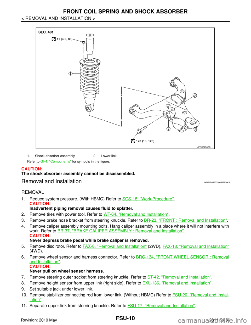
1. Shock absorber assembly 2. Lower link
Refer to GI-4, "
Components" for symbols in the figure.
JPEIA0256GB
Revision: 2010 May2011 QX56
Page 2956 of 5598
FSU-14
< REMOVAL AND INSTALLATION >
LOWER LINK
LOWER LINK
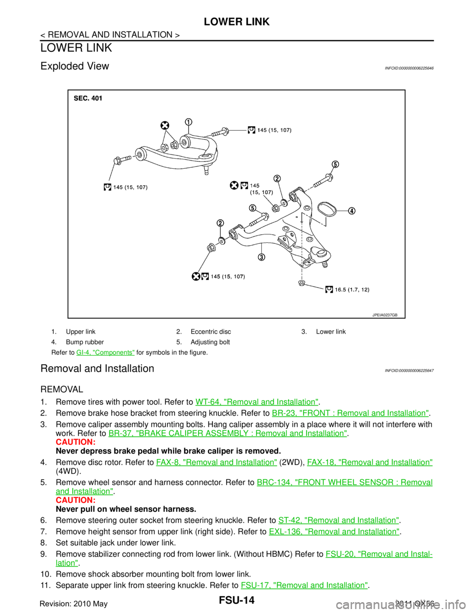
Exploded ViewINFOID:0000000006225646
Removal and InstallationINFOID:0000000006225647
REMOVAL
1. Remove tires with power tool. Refer to WT-64, "Removal and Installation".
2. Remove brake hose bracket from steering knuckle. Refer to BR-23, "
FRONT : Removal and Installation".
3. Remove caliper assembly mounting bolts. Hang caliper assembly in a place where it will not interfere with work. Refer to BR-37, "
BRAKE CALIPER ASSEMBLY : Removal and Installation".
CAUTION:
Never depress brake pedal while brake caliper is removed.
4. Remove disc rotor. Refer to FA X - 8 , "
Removal and Installation" (2WD), FAX-18, "Removal and Installation"
(4WD).
5. Remove wheel sensor and harness connector. Refer to BRC-134, "
FRONT WHEEL SENSOR : Removal
and Installation".
CAUTION:
Never pull on wheel sensor harness.
6. Remove steering outer socket fr om steering knuckle. Refer to ST-42, "
Removal and Installation".
7. Remove height sensor from upper link (right side). Refer to EXL-136, "
Removal and Installation".
8. Set suitable jack under lower link.
9. Remove stabilizer connecting rod from lower link. (Without HBMC) Refer to FSU-20, "
Removal and Instal-
lation".
10. Remove shock absorber mounting bolt from lower link.
11. Separate upper link from steering knuckle. Refer to FSU-17, "
Removal and Installation".
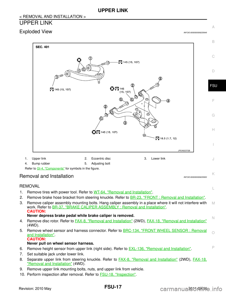
1. Upper link 2. Eccentric disc 3. Lower link
4. Bump rubber 5. Adjusting bolt
Refer to GI-4, "
Components" for symbols in the figure.
JPEIA0237GB
Revision: 2010 May2011 QX56
Page 2958 of 5598
FSU-16
< REMOVAL AND INSTALLATION >
LOWER LINK
2. Move tip of ball stud in axial direction to check for looseness.
If axial end play exceeds standard range, replace lower link assembly.
INSPECTION AFTER INSTALLATION
1. Check wheel sensor harness for proper connection. Refer to BRC-134, "FRONT WHEEL SENSOR :
Exploded View".
2. Check wheel alignment. Refer to FSU-7, "
Inspection".
3. Adjust neutral position of steering angle sensor. Refer to BRC-64, "
Work Procedure".
4. Adjust levelizer adjustment of height sensor. Refer to EXL-61, "
LEVELIZER ADJUSTMENT : Special
Repair Requirement".
Axial end play : Refer to
FSU-21, "
Ball Joint".
Revision: 2010 May2011 QX56
Page 2959 of 5598
UPPER LINKFSU-17
< REMOVAL AND INSTALLATION >
C
DF
G H
I
J
K L
M A
B
FSU
N
O P
UPPER LINK
Exploded ViewINFOID:0000000006225649
Removal and InstallationINFOID:0000000006225650
REMOVAL
1. Remove tires with power tool. Refer to WT-64, "Removal and Installation".
2. Remove brake hose bracket from steering knuckle. Refer to BR-23, "
FRONT : Removal and Installation".
3. Remove caliper assembly mounting bolts. Hang caliper assembly in a place where it will not interfere with work. Refer to BR-37, "
BRAKE CALIPER ASSEMBLY : Removal and Installation".
CAUTION:
Never depress brake pedal while brake caliper is removed.
4. Remove disc rotor. Refer to FA X - 8 , "
Removal and Installation" (2WD), FAX-18, "Removal and Installation"
(4WD).
5. Remove wheel sensor and harness connector. Refer to BRC-134, "
FRONT WHEEL SENSOR : Removal
and Installation".
CAUTION:
Never pull on wheel sensor harness.
6. Remove height sensor from upper link (right side). Refer to EXL-136, "
Removal and Installation".
7. Set suitable jack under lower link.
8. Separate upper link from steering knuckle. Refer to FA X - 8 , "
Removal and Installation" (2WD), FAX-18,
"Removal and Installation" (4WD).
9. Remove upper link mounting bolts, nuts, and upper link from vehicle.
10. Perform inspection after removal. Refer to FSU-18, "
Inspection".
1. Upper link 2. Eccentric disc 3. Lower link
4. Bump rubber 5. Adjusting bolt
Refer to GI-4, "
Components" for symbols in the figure.
JPEIA0237GB
Revision: 2010 May2011 QX56
Page 2960 of 5598
FSU-18
< REMOVAL AND INSTALLATION >
UPPER LINK
INSTALLATION
Note the following, and install in the reverse order of removal.
Perform final tightening of bolts and nuts at the vehicle installation position (rubber bushing), under unladenconditions with tires on level ground.
Perform inspection after installation. Refer to FSU-18, "
Inspection".
InspectionINFOID:0000000006225651
INSPECTION AFTER REMOVAL
Appearance
Check the following items, and replace the part if necessary.
Upper link and bushing for deformation, cracks or damage.
Ball joint boot for cracks or other damage, and also for grease leakage.
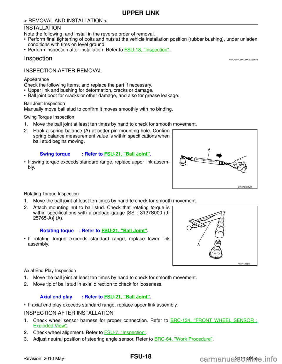
Ball Joint Inspection
Manually move ball stud to confirm it moves smoothly with no binding.
Swing Torque Inspection
1. Move the ball joint at least ten times by hand to check for smooth movement.
2. Hook a spring balance (A) at cotter pin mounting hole. Confirm
spring balance measurement value is within specifications when
ball stud begins moving.
If swing torque exceeds standard range, replace upper link assem- bly.
Rotating Torque Inspection
1. Move the ball joint at least ten times by hand to check for smooth movement.
2. Attach mounting nut to ball stud. Check that rotating torque is
within specifications with a preload gauge [SST: 3127S000 (J-
25765-A)] (A).
If rotating torque exceeds standard range, replace lower link assembly.
Axial End Play Inspection
1. Move the ball joint at least ten times by hand to check for smooth movement.
2. Move tip of ball stud in axial direction to check for looseness.
If axial end play exceeds standard range, replace upper link assembly.
INSPECTION AFTER INSTALLATION
1. Check wheel sensor harness for proper connection. Refer to BRC-134, "FRONT WHEEL SENSOR :
Exploded View".
2. Check wheel alignment. Refer to FSU-7, "
Inspection".
3. Adjust neutral position of steering angle sensor. Refer to BRC-64, "
Work Procedure".
Swing torque : Refer to
FSU-21, "
Ball Joint".
JPEIA0005ZZ
Rotating toque : Refer to FSU-21, "Ball Joint".
PDIA1258E
Axial end play : Refer to FSU-21, "Ball Joint".
Revision: 2010 May2011 QX56
Page 2965 of 5598
GI-1
GENERAL INFORMATION
C
DE
F
G H
I
J
K L
M B
GI
SECTION GI
N
O P
CONTENTS
GENERAL INFORMATION
HOW TO USE THIS MANU AL ......................3
HOW TO USE THIS MANUAL ....................... .....3
Description .......................................................... ......3
Terms ........................................................................3
Units ..........................................................................3
Contents ....................................................................3
Relation between Illustrations and Descriptions .......4
Components ..............................................................4
HOW TO FOLLOW TROUBLE DIAGNOSES .....6
Description ................................................................6
How to Follow Test Groups in Trouble Diagnosis ......6
Key to Symbols Signifying Measurements or Pro-
cedures ............................................................... ......
7
HOW TO READ WIRING DIAGRAMS ................9
Connector Symbols ............................................. ......9
Sample/Wiring Diagram -Example- .........................10
Connector Information .............................................12
ABBREVIATIONS .......................................... ....14
Abbreviation List .................................................. ....14
TIGHTENING TORQUE OF STANDARD
BOLTS ................................................................
19
Description .......................................................... ....19
Tightening Torque Table (New Standard Includ-
ed) ...........................................................................
19
RECOMMENDED CHEMICAL PRODUCTS
AND SEALANTS ................................................
22
Recommended Chemical Products and Sealants ....22
VEHICLE INFORMATION ............................23
IDENTIFICATION INFORMATION ................. ....23
Model Variation ................................................... ....23
Information About Identification or Model Code ......23
Dimensions .............................................................25
Wheels & Tires ........................................................25
PRECAUTION ..............................................26
PRECAUTIONS .................................................26
Description ........................................................... ....26
Precaution for Supplemental Restraint System
(SRS) "AIR BAG" and "SEAT BELT PRE-TEN-
SIONER" .................................................................
26
Precautions For Xenon Headlamp Service .............26
Precaution Necessary for Steering Wheel Rota-
tion after Battery Disconnect ...................................
27
Precaution for Procedure without Cowl Top Cover ....27
General Precautions ................................................27
Three Way Catalyst .................................................29
Multiport Fuel Injection System or Engine Control
System .....................................................................
29
Hoses ......................................................................29
Engine Oils ..............................................................30
Air Conditioning .......................................................31
Fuel ..........................................................................31
LIFTING POINT .................................................32
Pantograph Jack ......................................................32
Garage Jack and Safety Stand ................................32
2-Pole Lift ................................................................33
TOW TRUCK TOWING .....................................34
Tow Truck Towing ...................................................34
Vehicle Recovery (Freeing a Stuck Vehicle) ...........34
BASIC INSPECTION ...................................36
SERVICE INFORMATION FOR ELECTRICAL
INCIDENT ..........................................................
36
Work Flow ............................................................ ....36
Control Units and Electrical Parts ............................36
How to Check Terminal ...........................................37
Intermittent Incident .................................................40
Circuit Inspection .....................................................43
CONSULT-III/GST CHECKING SYSTEM .........48
Description ...............................................................48
CONSULT-III Function and System Application*1 ....48
Revision: 2010 May2011 QX56
Page 2991 of 5598
PRECAUTIONSGI-27
< PRECAUTION >
C
DE
F
G H
I
J
K L
M B
GI
N
O P
Precaution Necessary for Steering Wh eel Rotation after Battery Disconnect
INFOID:0000000006280868
NOTE:
Before removing and installing any control units, first tu rn the push-button ignition switch to the LOCK posi-
tion, then disconnect both battery cables.
After finishing work, confirm that all control unit connectors are connected properly, then re-connect both
battery cables.
Always use CONSULT-III to perform self-diagnosis as a part of each function inspection after finishing work.
If a DTC is detected, perform trouble diagnos is according to self-diagnosis results.
For vehicle with steering lock unit, if the battery is disconnected or discharged, the steering wheel will lock and
cannot be turned.
If turning the steering wheel is required with the batte ry disconnected or discharged, follow the operation pro-
cedure below before starting the repair operation.
OPERATION PROCEDURE
1. Connect both battery cables. NOTE:
Supply power using jumper cables if battery is discharged.
2. Turn the push-button ignition switch to ACC position. (At this time, the steering lock will be released.)
3. Disconnect both battery cables. The steering lock wil l remain released with both battery cables discon-
nected and the steering wheel can be turned.
4. Perform the necessary repair operation.
5. When the repair work is completed, re-connect both battery cables. With the brake pedal released, turn
the push-button ignition switch from ACC position to ON position, then to LOCK position. (The steering
wheel will lock when the push-button ignition switch is turned to LOCK position.)
6. Perform self-diagnosis check of a ll control units using CONSULT-III.
Precaution for Procedure without Cowl Top CoverINFOID:0000000006280869
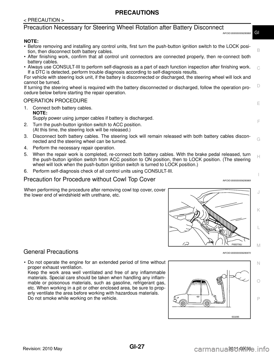
When performing the procedure after removing cowl top cover, cover
the lower end of windshield with urethane, etc.
General PrecautionsINFOID:0000000006280870
Do not operate the engine for an extended period of time without
proper exhaust ventilation.
Keep the work area well ventilated and free of any inflammable
materials. Special care should be taken when handling any inflam-
mable or poisonous materials, such as gasoline, refrigerant gas,
etc. When working in a pit or ot her enclosed area, be sure to prop-
erly ventilate the area before working with hazardous materials.
Do not smoke while working on the vehicle.
PIIB3706J
SGI285
Revision: 2010 May2011 QX56