2011 INFINITI QX56 engine oil
[x] Cancel search: engine oilPage 3663 of 5598
LU-10
< PERIODIC MAINTENANCE >
OIL FILTER
4. Check engine oil level and add engine oil as required.
Revision: 2010 May2011 QX56
Page 3664 of 5598
OIL COOLERLU-11
< REMOVAL AND INSTALLATION >
C
DE
F
G H
I
J
K L
M A
LU
NP
O
REMOVAL AND INSTALLATION
OIL COOLER
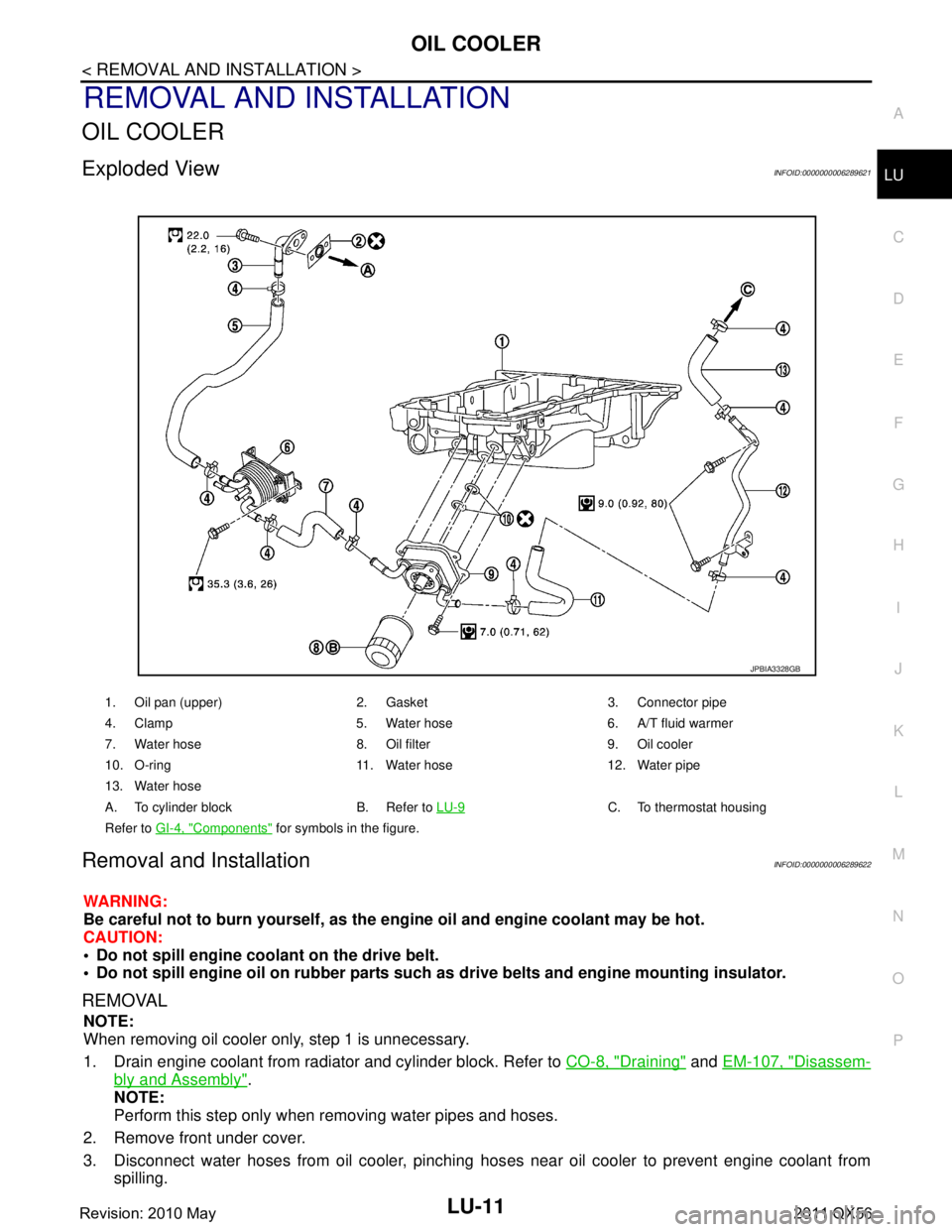
Exploded ViewINFOID:0000000006289621
Removal and InstallationINFOID:0000000006289622
WARNING:
Be careful not to burn yourself, as the en
gine oil and engine coolant may be hot.
CAUTION:
Do not spill engine coolant on the drive belt.
Do not spill engine oil on rubber parts such as drive belts and engine mounting insulator.
REMOVAL
NOTE:
When removing oil cooler only, step 1 is unnecessary.
1. Drain engine coolant from radiator and cylinder block. Refer to CO-8, "
Draining" and EM-107, "Disassem-
bly and Assembly".
NOTE:
Perform this step only when removing water pipes and hoses.
2. Remove front under cover.
3. Disconnect water hoses from oil cooler, pinching hos es near oil cooler to prevent engine coolant from
spilling.
1. Oil pan (upper) 2. Gasket 3. Connector pipe
4. Clamp 5. Water hose 6. A/T fluid warmer
7. Water hose 8. Oil filter 9. Oil cooler
10. O-ring 11. Water hose 12. Water pipe
13. Water hose
A. To cylinder block B. Refer to LU-9
C. To thermostat housing
Refer to GI-4, "
Components" for symbols in the figure.
JPBIA3328GB
Revision: 2010 May2011 QX56
Page 3665 of 5598
LU-12
< REMOVAL AND INSTALLATION >
OIL COOLER
CAUTION:
Perform this step when engine is cold.
4. Remove oil filter. Refer to LU-9, "
Removal and Installation".
5. Remove connector bolt, and remove oil cooler.
INSTALLATION
Installation is in the reverse order of removal, paying attention to the following:
Confirm that no foreign objects are adhering to the sealing surfaces of the oil cooler and oil pan.
InspectionINFOID:0000000006289623
INSPECTION AFTER REMOVAL
Oil Cooler
Check oil cooler for cracks. Check oil cooler for clogging by blowing compressed air through engine coolant
inlet. If necessary, replace oil cooler assembly.
Relief Valve
Inspect relief valve for movement, cracks and breaks by pushing the ball. If replacement is necessary, remove
the valve by prying it out using a suitable tool. Install a new valve in place by tapping it in.
INSPECTION AFTER INSTALLATION
1. Check engine oil and engine coolant levels and add engine oil and engine coolant. Refer to LU-7, "Inspec-
tion" and CO-8, "Inspection".
2. Start the engine, and check for l eaks of engine oil or engine coolant.
3. Stop the engine and wait for 10 minutes.
4. Check the engine oil level and engine coolant level again. Refer to LU-7, "
Inspection" and CO-8, "Inspec-
tion"
Revision: 2010 May2011 QX56
Page 3666 of 5598
OIL PUMPLU-13
< REMOVAL AND INSTALLATION >
C
DE
F
G H
I
J
K L
M A
LU
NP
O
OIL PUMP
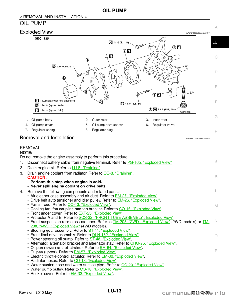
Exploded ViewINFOID:0000000006289624
Removal and InstallationINFOID:0000000006289625
REMOVAL
NOTE:
Do not remove the engine assembly to perform this procedure.
1. Disconnect battery cable from
negative terminal. Refer to PG-165, "
Exploded View".
2. Drain engine oil. Refer to LU-8, "
Draining".
3. Drain engine coolant from radiator. Refer to CO-8, "
Draining".
CAUTION:
Perform this step when engine is cold.
Never spill engine coolant on drive belts.
4. Remove the following components and related parts: Air cleaner case assembly and air duct. Refer to EM-27, "
Exploded View".
Drive belt auto tensioner and idler pulley. Refer to EM-26, "
Exploded View".
Fan shroud. Refer to CO-13, "
Exploded View".
Cooling fan, fan coupling and fan bracket. Refer to CO-16, "
Exploded View".
Front under cover. Refer to EXT-25, "
Exploded View".
Protector A and B. Refer to SCS-32, "
FRONT TUBE ASSEMBLY : Exploded View".
Front suspension rear cross member. Refer to TM-205, "
2WD : Exploded View" (2WD models) or TM-
208, "4WD : Exploded View" (4WD models).
Steering gear assembly. Refer to ST-41, "
Exploded View".
Front final drive assembly. Refer to DLN-162, "
Exploded View".
Power steering oil pump. Refer to ST-48, "
Exploded View".
Alternator, alternator bracket and alternator stay. Refer to CHG-25, "
Exploded View".
Oil pan (lower) and oil strainer. Refer to EM-54, "
Exploded View".
Oil pan (upper). Refer to EM-57, "
Exploded View".
Electric throttle control actuator. Refer to EM-30, "
Exploded View".
Radiator hoses. Refer to CO-13, "
Exploded View".
Water suction hose and water suction pipe. Refer to CO-20, "
Exploded View".
Water pump pulley. Refer to CO-18, "
Exploded View".
Rocker cover. Refer to EM-33, "
Exploded View".
WBIA0415E
1. Oil pump body 2. Outer rotor 3. Inner rotor
4. Oil pump cover 5. Oil pump drive spacer 6. Regulator valve
7. Regulator spring 8. Regulator plug
Revision: 2010 May2011 QX56
Page 3669 of 5598
LU-16
< REMOVAL AND INSTALLATION >
OIL PUMP
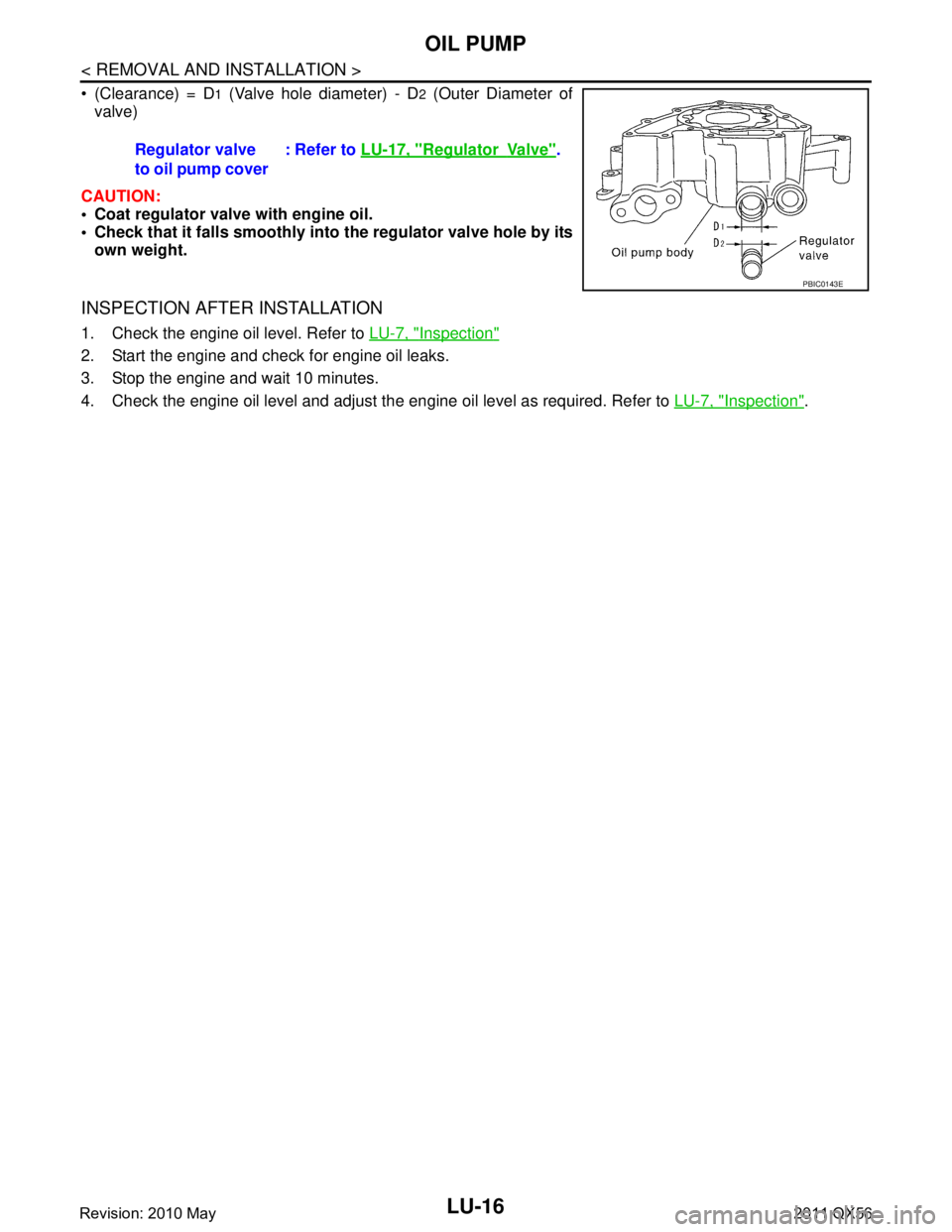
(Clearance) = D1 (Valve hole diameter) - D2 (Outer Diameter of
valve)
CAUTION:
Coat regulator valve with engine oil.
Check that it falls smoothly into the regulator valve hole by its
own weight.
INSPECTION AFTER INSTALLATION
1. Check the engine oil level. Refer to LU-7, "Inspection"
2. Start the engine and check for engine oil leaks.
3. Stop the engine and wait 10 minutes.
4. Check the engine oil level and adjust the engine oil level as required. Refer to LU-7, "
Inspection".
Regulator valve
to oil pump cover
: Refer to
LU-17, "
RegulatorVa l v e".
PBIC0143E
Revision: 2010 May2011 QX56
Page 3670 of 5598
SERVICE DATA AND SPECIFICATIONS (SDS)
LU-17
< SERVICE DATA AND SPECIFICATIONS (SDS)
C
D E
F
G H
I
J
K L
M A
LU
NP
O
SERVICE DATA AND SPECIFICATIONS (SDS)
SERVICE DATA AND SPECIFICATIONS (SDS)
Periodical Maintenance SpecificationINFOID:0000000006289628
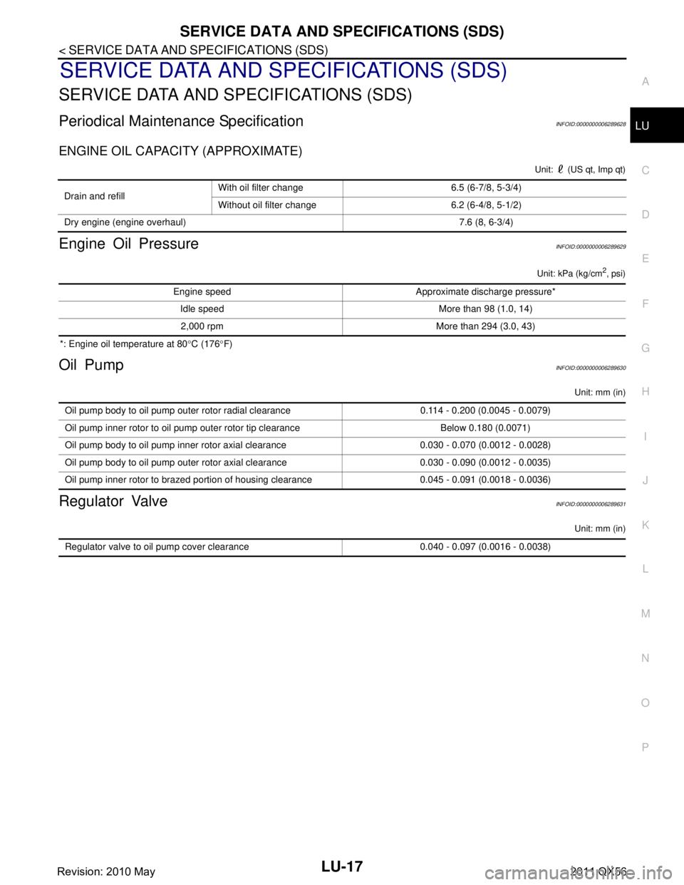
ENGINE OIL CAPACITY (APPROXIMATE)
Unit: (US qt, Imp qt)
Engine Oil PressureINFOID:0000000006289629
Unit: kPa (kg/cm2, psi)
*: Engine oil temperature at 80
°C (176 °F)
Oil PumpINFOID:0000000006289630
Unit: mm (in)
Regulator ValveINFOID:0000000006289631
Unit: mm (in)
Drain and refill With oil filter change 6.5 (6-7/8, 5-3/4)
Without oil filter change 6.2 (6-4/8, 5-1/2)
Dry engine (engine overhaul) 7.6 (8, 6-3/4)
Engine speed Approximate discharge pressure* Idle speed More than 98 (1.0, 14)2,000 rpm More than 294 (3.0, 43)
Oil pump body to oil pump outer rotor radial clearance 0.114 - 0.200 (0.0045 - 0.0079)
Oil pump inner rotor to oil pump outer rotor tip clearance Below 0.180 (0.0071)
Oil pump body to oil pump inner rotor axial clearance 0.030 - 0.070 (0.0012 - 0.0028)
Oil pump body to oil pump outer rotor axial clearance 0.030 - 0.090 (0.0012 - 0.0035)
Oil pump inner rotor to brazed portion of housing clearance 0.045 - 0.091 (0.0018 - 0.0036)
Regulator valve to oil pump cover clearance 0.040 - 0.097 (0.0016 - 0.0038)
Revision: 2010 May2011 QX56
Page 3671 of 5598
MA-1
MAINTENANCE
C
DE
F
G H
I
J
K L
M B
MA
SECTION MA
N
O A
CONTENTS
MAINTENANCE
PREPARATION .............
...............................3
PREPARATION .............................................. .....3
Special Service Tool ........................................... ......3
Commercial Service Tool ..........................................3
PERIODIC MAINTENANCE ..........................4
GENERAL MAINTENANCE ........................... .....4
Explanation of General Maintenance .................. ......4
PERIODIC MAINTENANCE ................................6
Introduction of Periodic Maintenance .................. ......6
Schedule 1 ................................................................6
Schedule 2 ................................................................8
RECOMMENDED FLUIDS AND LUBRI-
CANTS ................................................................
10
Fluids and Lubricants .......................................... ....10
Engine Oil Recommendation ..................................10
Anti-Freeze Coolant Mixture Ratio ..........................11
ENGINE MAINTENANCE ...................................12
DRIVE BELTS ....................................................... ....12
DRIVE BELTS : Exploded View ..............................12
DRIVE BELTS : Checking .......................................12
DRIVE BELTS : Tension Adjustment .....................12
ENGINE COOLANT ............................................... ....12
ENGINE COOLANT : Inspection .............................12
ENGINE COOLANT : Draining ................................13
ENGINE COOLANT : Refilling ................................13
ENGINE COOLANT : Flushing ...............................15
RESERVOIR TANK CAP ..........................................15
RESERVOIR TANK CAP : Inspection ................. ....15
RADIATOR ............................................................ ....16
RADIATOR : Inspection ..........................................16
FUEL LINES .......................................................... ....16
FUEL LINES : Inspection ........................................17
AIR CLEANER FILTER ......................................... ....17
AIR CLEANER FILTER : Removal and Installation
....
17
ENGINE OIL ........................................................... ....17
ENGINE OIL : Draining ............................................17
ENGINE OIL : Refilling ............................................17
OIL FILTER ............................................................ ....18
OIL FILTER : Removal and Installation ...................18
SPARK PLUG ........................................................ ....18
SPARK PLUG : Removal and Installation ...............19
SPARK PLUG : Inspection ......................................19
EVAP VAPOR LINES ............................................ ....20
EVAP VAPOR LINES : Inspection ...........................20
CHASSIS MAINTENANCE ...............................21
EXHAUST SYSTEM . ..................................................21
EXHAUST SYSTEM : Inspec tion ............................21
A/T FLUID .............................................................. ....21
A/T FLUID : Inspection ............................................21
TRANSFER FLUID ................................................ ....21
TRANSFER FLUID : Inspection ..............................21
TRANSFER FLUID : Draining .................................21
TRANSFER FLUID : Refilling ..................................22
FRONT PROPELLER SHAFT: 2F P15 ................. ....22
FRONT PROPELLER SHAFT: 2F P15 : Inspec-
tion ...........................................................................
22
REAR PROPELLER SHAFT: 2F P26 .................... ....23
REAR PROPELLER SHAFT: 2F P26 : Inspection ....23
REAR PROPELLER SHAFT: 2S1410 ................... ....23
REAR PROPELLER SHAFT: 2S1410 : Inspection ....23
FRONT DIFFERENTIAL GEAR OIL: R180A ........ ....24
FRONT DIFFERENTIAL GEAR OIL: R180A : In-
spection ...................................................................
24
Revision: 2010 May2011 QX56
Page 3672 of 5598
MA-2
FRONT DIFFERENTIAL GEAR OIL: R180A :
Draining ..................................................................
24
FRONT DIFFERENTIAL GEAR OIL: R180A : Re-
filling .......................................................................
25
REAR DIFFERENTIAL GEAR OIL: R230 ............. ...25
REAR DIFFERENTIAL GEAR OIL: R230 : Inspec-
tion ..........................................................................
25
REAR DIFFERENTIAL GEAR OIL: R230 : Drain-
ing ...........................................................................
25
REAR DIFFERENTIAL GEAR OIL: R230 : Refill-
ing ...........................................................................
26
WHEELS (BONDING WEIGHT TYPE) .....................26
WHEELS (BONDING WEIGHT TYPE) : Adjust-
ment ..................................................................... ...
26
BRAKE FLUID LEVEL AND LEAKS ........................27
BRAKE FLUID LEVEL AND LEAKS : Inspection ...28
BRAKE LINES AND CABLES ............................... ...28
BRAKE LINES AND CABLES : Inspection .............28
BRAKE FLUID ....................................................... ...28
BRAKE FLUID : Bleeding Brake System ................28
DISC BRAKE ......................................................... ...30
DISC BRAKE : Inspection ......................................30
DISC BRAKE : Front Disc Brake ............................31
DISC BRAKE : Rear Disc Brake .............................31
STEERING GEAR AND LINKAGE ........................ ...31
STEERING GEAR AND LINKAGE : Inspection ......31
POWER STEERING FLUID AND LINES ............... ...32
POWER STEERING FLUID AND LINES : Inspec-
tion ..........................................................................
32
AXLE AND SUSPENSION PARTS ...........................32
AXLE AND SUSPENSION PARTS : Inspection .. ...32
DRIVE SHAFT ........................................................ ...33
DRIVE SHAFT : Inspection .....................................33
BODY MAINTENANCE .....................................34
LOCKS, HINGES AND HOOD LATCH .................. ...34
LOCKS, HINGES AND HOOD LATCH : Lubricat-
ing ...........................................................................
34
SEAT BELT, BUCKLES, RETRACTORS, AN-
CHORS AND ADJUSTERS ................................... ...
34
SEAT BELT, BUCKLES, RETRACTORS, AN-
CHORS AND ADJUSTERS : Inspection .................
34
SERVICE DATA AND SPECIFICATIONS
(SDS) .......... ................................................
35
SERVICE DATA AND SPECIFICATIONS
(SDS) .............................................................. ...
35
DRIVE BELTS ........................................................ ...35
DRIVE BELTS : Drive Belts ....................................35
ENGINE COOLANT ............................................... ...35
ENGINE COOLANT :
Periodical Maintenance Specification ....................
35
ENGINE OIL ........................................................... ...35
ENGINE OIL : Periodical Maintenance Specifica-
tion ..........................................................................
35
SPARK PLUG ........................................................ ...35
SPARK PLUG : Spark Plug ....................................35
ROAD WHEEL ....................................................... ...35
ROAD WHEEL : Road Wheel .................................35
Revision: 2010 May2011 QX56