2011 INFINITI QX56 engine oil
[x] Cancel search: engine oilPage 3105 of 5598
REAR A/C UNITHA-49
< REMOVAL AND INSTALLATION >
C
DE
F
G H
J
K L
M A
B
HA
N
O P
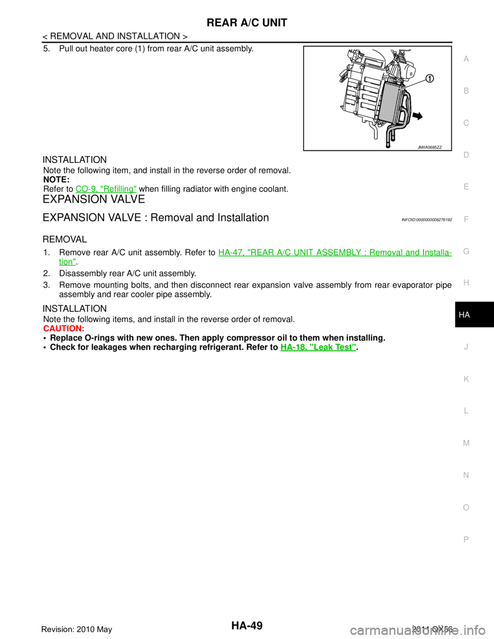
5. Pull out heater core (1) from rear A/C unit assembly.
INSTALLATION
Note the following item, and install in the reverse order of removal.
NOTE:
Refer to CO-9, "
Refilling" when filling radiator with engine coolant.
EXPANSION VALVE
EXPANSION VALVE : Removal and InstallationINFOID:0000000006276192
REMOVAL
1. Remove rear A/C unit assembly. Refer to HA-47, "REAR A/C UNIT ASSEMBLY : Removal and Installa-
tion".
2. Disassembly rear A/C unit assembly.
3. Remove mounting bolts, and then disconnect rear exp ansion valve assembly from rear evaporator pipe
assembly and rear cooler pipe assembly.
INSTALLATION
Note the following items, and install in the reverse order of removal.
CAUTION:
Replace O-rings with new ones. Then apply compressor oil to them when installing.
Check for leakages when recharging refrigerant. Refer to HA-18, "
Leak Test".
JMIIA0685ZZ
Revision: 2010 May2011 QX56
Page 3106 of 5598
HA-50
< SERVICE DATA AND SPECIFICATIONS (SDS)
SERVICE DATA AND SPECIFICATIONS (SDS)
SERVICE DATA AND SPECIFICATIONS (SDS)
SERVICE DATA AND SPECIFICATIONS (SDS)
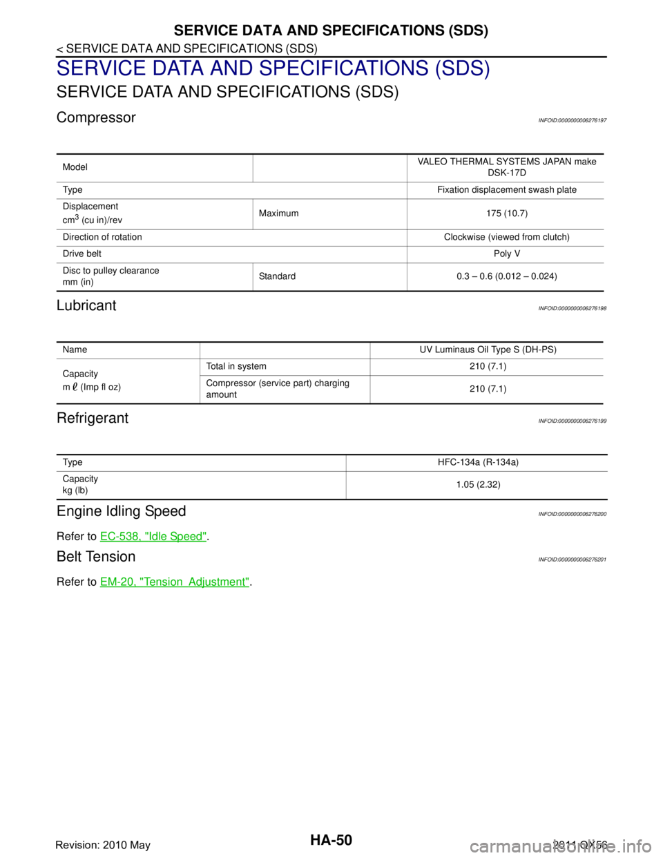
CompressorINFOID:0000000006276197
LubricantINFOID:0000000006276198
RefrigerantINFOID:0000000006276199
Engine Idling SpeedINFOID:0000000006276200
Refer to EC-538, "Idle Speed".
Belt TensionINFOID:0000000006276201
Refer to EM-20, "TensionAdjustment".
Model VALEO THERMAL SYSTEMS JAPAN make
DSK-17D
Ty p e Fixation displacement swash plate
Displacement
cm
3 (cu in)/rev Maximum 175 (10.7)
Direction of rotation Clockwise (viewed from clutch)
Drive belt Poly V
Disc to pulley clearance
mm (in) Standard 0.3 – 0.6 (0.012 – 0.024)
Name
UV Luminaus Oil Type S (DH-PS)
Capacity
m (Imp fl oz) Total in system 210 (7.1)
Compressor (service part) charging
amount
210 (7.1)
Ty p e
HFC-134a (R-134a)
Capacity
kg (lb) 1.05 (2.32)
Revision: 2010 May2011 QX56
Page 3123 of 5598
![INFINITI QX56 2011 Factory Service Manual
SYSTEMHAC-17
< SYSTEM DESCRIPTION > [AUTOMATIC AIR CONDITIONING]
C
D
E
F
G H
J
K L
M A
B
HAC
N
O P
FRONT AUTOMATIC AIR CONDITIONIN G SYSTEM : Air Outlet ControlINFOID:0000000006275864
While air out INFINITI QX56 2011 Factory Service Manual
SYSTEMHAC-17
< SYSTEM DESCRIPTION > [AUTOMATIC AIR CONDITIONING]
C
D
E
F
G H
J
K L
M A
B
HAC
N
O P
FRONT AUTOMATIC AIR CONDITIONIN G SYSTEM : Air Outlet ControlINFOID:0000000006275864
While air out](/manual-img/42/57033/w960_57033-3122.png)
SYSTEMHAC-17
< SYSTEM DESCRIPTION > [AUTOMATIC AIR CONDITIONING]
C
D
E
F
G H
J
K L
M A
B
HAC
N
O P
FRONT AUTOMATIC AIR CONDITIONIN G SYSTEM : Air Outlet ControlINFOID:0000000006275864
While air outlet is in automatic control, A/C auto amp. selects the
front mode door position depending on a target front air mix door
angle and outlet air temperature calculated from sunload.
If ambient temperature is excessively low, D/F is selected to pre- vent windshield fogging when air outlet is set to FOOT.
FRONT AUTOMATIC AIR CONDITIONIN G SYSTEM : Compressor Control
INFOID:0000000006275865
DESCRIPTION
When the compressor activation condition is satisfied while blower motor is activated, A/C auto amp. trans-
mits A/C ON signal and blower fan ON signal to ECM via CAN communication.
ECM judges that the compressor can be activated depending on each sensors state (refrigerant pressure sensor signal, and others). And transmits A/C compress or request signal to IPDM E/R via CAN communica-
tion.
IPDM E/R turns A/C relay ON and activates the compressor depending on request from ECM.
COMPRESSOR PROTECTION CONTROL AT PRESSURE MALFUNCTION
When high-pressure side value that is detected by refri gerant pressure sensor is as per the following state,
ECM requests IPDM E/R to turn A/C relay OFF and stops the compressor.
3.12 MPa (31.82 kg/cm
2, 452.4 psi) or more (When the engine speed is less than 1,500 rpm)
2.74 MPa (27.95 kg/cm
2, 397.3 psi) or more (When the engine speed is 1,500 rpm or more)
0.14 MPa (1.43 kg/cm
2, 20.3 psi) or less
COMPRESSOR OIL CIRCULATION CONTROL
When the engine starts while the engine coolant temperature is 56 °C (133 °F) or less, ECM activates the com-
pressor for approximately 6 seconds and circulates the compressor lubricant once.
LOW TEMPERATURE PROTECTION CONTROL
When intake sensor detects that front evaporator fin temperature is
2.5 °C (37 °F) or less, A/C auto amp. requests ECM to turn com-
pressor OFF, and stops the compressor.
When the front evaporator fin temperature returns to 5.0 °C (41 °F)
or more, the compressor is activated.
OPERATING RATE CONTROL
When set temperature is other than fully cold or air out let is “VENT”, “B/L” or “FOOT” A/C auto amp. controls
the compressor activation depending on ambient temperature.
AIR CONDITIONING CUT CONTROL
When set engine is running is excessively high load conditi on, ECM requests IPDM E/R to turn A/C relay OFF,
and stops the compressor. Refer to EC-47, "
AIR CONDITIONING CUT CONTRO L : System Description" for
details.
JMIIA0730GB
JMIIA0742GB
Revision: 2010 May2011 QX56
Page 3654 of 5598

LU-1
ENGINE
C
DE
F
G H
I
J
K L
M
SECTION LU
A
LU
N
O P
CONTENTS
ENGINE LUBRICATION SYSTEM
PRECAUTION ................ ...............................2
PRECAUTIONS .............................................. .....2
Liquid Gasket ..................................................... ......2
PREPARATION ............................................3
PREPARATION .............................................. .....3
Special Service Tool ........................................... ......3
Commercial Service Tool ..........................................3
SYSTEM DESCRIPTION ..............................5
LUBRICATION SYSTEM ............................... .....5
Engine Lubrication System ................................. ......5
Engine Lubrication System Schematic ......................6
PERIODIC MAINTENANCE ..........................7
ENGINE OIL ................................................... .....7
Inspection ............................................................ ......7
Draining .....................................................................8
Refilling .....................................................................8
OIL FILTER .........................................................9
Removal and Installation ..................................... ......9
Inspection ............................................................ .....9
REMOVAL AND INSTALLATION ...............11
OIL COOLER ....................................................11
Exploded View ..................................................... ....11
Removal and Installation .........................................11
Inspection ................................................................12
OIL PUMP .........................................................13
Exploded View .........................................................13
Removal and Installation .........................................13
Disassembly and Assembly .....................................14
Inspection ................................................................14
SERVICE DATA AND SPECIFICATIONS
(SDS) ............... .............................................
17
SERVICE DATA AND SPECIFICATIONS
(SDS) .................................................................
17
Periodical Maintenance Specification .................. ....17
Engine Oil Pressure ...............................................17
Oil Pump .................................................................17
Regulator Valve ......................................................17
Revision: 2010 May2011 QX56
Page 3655 of 5598
LU-2
< PRECAUTION >
PRECAUTIONS
PRECAUTION
PRECAUTIONS
Liquid GasketINFOID:0000000006289611
LIQUID GASKET APPLICATION PROCEDURE
1. Remove old liquid gasket adhering to the liquid gasket application surface and the mating surface.• Remove liquid gasket completely from the liquid gasket application surface, mounting bolts, and boltholes.
2. Wipe the liquid gasket application surface and the ma ting surface with white gasoline (lighting and heating
use) to remove adhering moisture, grease and foreign materials.
3. Apply liquid gasket to the liquid gasket application surface. Use Genuine RTV Silicone Seal ant or equivalent. Refer to GI-22, "
Recommended Chemical Prod-
ucts and Sealants".
Within five minutes of liquid gasket application, install the mating component.
If liquid gasket protrudes, wipe it off immediately.
Do not retighten mounting bolts or nuts after the installation.
After 30 minutes or more have passed from the installation, fill engine oil and engine coolant.
Revision: 2010 May2011 QX56
Page 3660 of 5598
ENGINE OILLU-7
< PERIODIC MAINTENANCE >
C
DE
F
G H
I
J
K L
M A
LU
NP
O
PERIODIC MAINTENANCE
ENGINE OIL
InspectionINFOID:0000000006289616
OIL LEVEL
NOTE:
Before starting engine, put vehicle horizontally and check
the engine oil level. If engine is already started, stop
it and allow 10 minutes before checking.
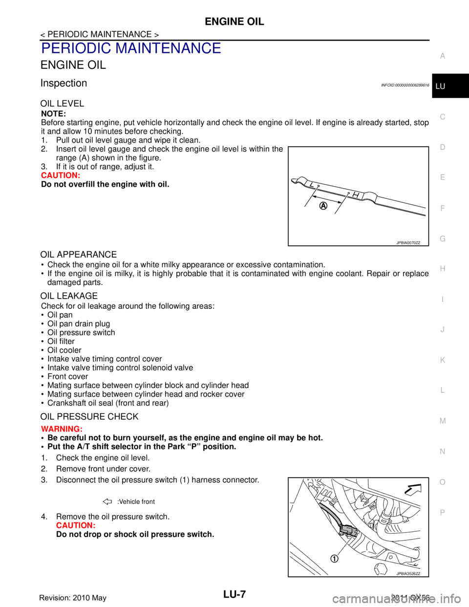
1. Pull out oil level gauge and wipe it clean.
2. Insert oil level gauge and check the engine oil level is within the range (A) shown in the figure.
3. If it is out of range, adjust it.
CAUTION:
Do not overfill the engine with oil.
OIL APPEARANCE
Check the engine oil for a white milky appearance or excessive contamination.
If the engine oil is milky, it is highly probable that it is contaminated with engine coolant. Repair or replace
damaged parts.
OIL LEAKAGE
Check for oil leakage around the following areas:
Oil pan
Oil pan drain plug
Oil pressure switch
Oil filter
Oil cooler
Intake valve timing control cover
Intake valve timing control solenoid valve
Front cover
Mating surface between cylinder block and cylinder head
Mating surface between cylinder head and rocker cover
Crankshaft oil seal (front and rear)
OIL PRESSURE CHECK
WARNING:
• Be careful not to burn yourself, as th e engine and engine oil may be hot.
Put the A/T shift selector in the Park “P” position.
1. Check the engine oil level.
2. Remove front under cover.
3. Disconnect the oil pressure switch (1) harness connector.
4. Remove the oil pressure switch. CAUTION:
Do not drop or shock oil pressure switch.
JPBIA0070ZZ
:Vehicle front
JPBIA3526ZZ
Revision: 2010 May2011 QX56
Page 3661 of 5598
![INFINITI QX56 2011 Factory Service Manual
LU-8
< PERIODIC MAINTENANCE >
ENGINE OIL
5. Install the oil pressure gauge [SST: ST25051001 (J25695-1)] (A)and hose [SST: ST25052000 (J25695-2)] (B).
6. Start the engine and warm it up to normal oper INFINITI QX56 2011 Factory Service Manual
LU-8
< PERIODIC MAINTENANCE >
ENGINE OIL
5. Install the oil pressure gauge [SST: ST25051001 (J25695-1)] (A)and hose [SST: ST25052000 (J25695-2)] (B).
6. Start the engine and warm it up to normal oper](/manual-img/42/57033/w960_57033-3660.png)
LU-8
< PERIODIC MAINTENANCE >
ENGINE OIL
5. Install the oil pressure gauge [SST: ST25051001 (J25695-1)] (A)and hose [SST: ST25052000 (J25695-2)] (B).
6. Start the engine and warm it up to normal operating temperature.
7. Check the engine oil pressure with engine running under no-load. Refer to LU-17, "
EngineOilPressure".
CAUTION:
If the difference is extreme, check the oil passages and oil pump for leaks and blockages.
8. After the inspections, install oil pressure switch as follows:
a. Remove old liquid gasket adhering to oil pressure switch and engine.
b. Apply liquid gasket and tighten oil pressure switch to the specification. Use Genuine RTV Silicone Seal ant or equivalent. Refer to GI-22, "
Recommended Chemical Prod-
ucts and Sealants".
c. After warming up engine, make sure there is no leakage of engine oil with engine running.
DrainingINFOID:0000000006289617
WARNING:
Be careful not to burn yourself, as th e engine and engine oil may be hot.
Prolonged and repeated contact with used engine oil may cause skin cancer; try to avoid direct skin
contact with used oil. If skin contact is made, wash thoroughly with soap or hand cleaner as soon as
possible.
1. Warm up the engine, and check for any oil leaks.
2. Stop the engine and wait for at least 10 minutes.
3. Remove drain plug and oil filler cap to drain the old oil.
RefillingINFOID:0000000006289618
1. Install drain plug with new washer. CAUTION:
Be sure to clean drain plug and install with new washer.
2. Refill with new engine oil. Engine oil specification and viscosity:
Refer to MA-10, "
Fluids and Lubricants".
CAUTION:
The refill capacity depends on the engine oi l temperature and drain time. Use these specifica-
tions for reference only.
Always use oil level gauge to determine the proper amount of engine oil in engine.
3. Warm up the engine and check area around drain plug and oil filter for engine oil leakage.
4. Stop the engine and wait for 10 minutes.
5. Check the engine oil level. Refer to LU-7, "
Inspection".
JPBIA0074ZZ
Oil pressure switch torque : Refer to EM-57, "Exploded View".
Tightening torque : Refer to EM-54, "
Exploded View".
Engine oil capacity : Refer to LU-17, "
Periodical Maintenance Specification".
Revision: 2010 May2011 QX56
Page 3662 of 5598
OIL FILTERLU-9
< PERIODIC MAINTENANCE >
C
DE
F
G H
I
J
K L
M A
LU
NP
O
OIL FILTER
Removal and InstallationINFOID:0000000006289619
REMOVAL
1. Remove front under cover.
2. Drain engine oil. Refer to
LU-8, "
Draining".
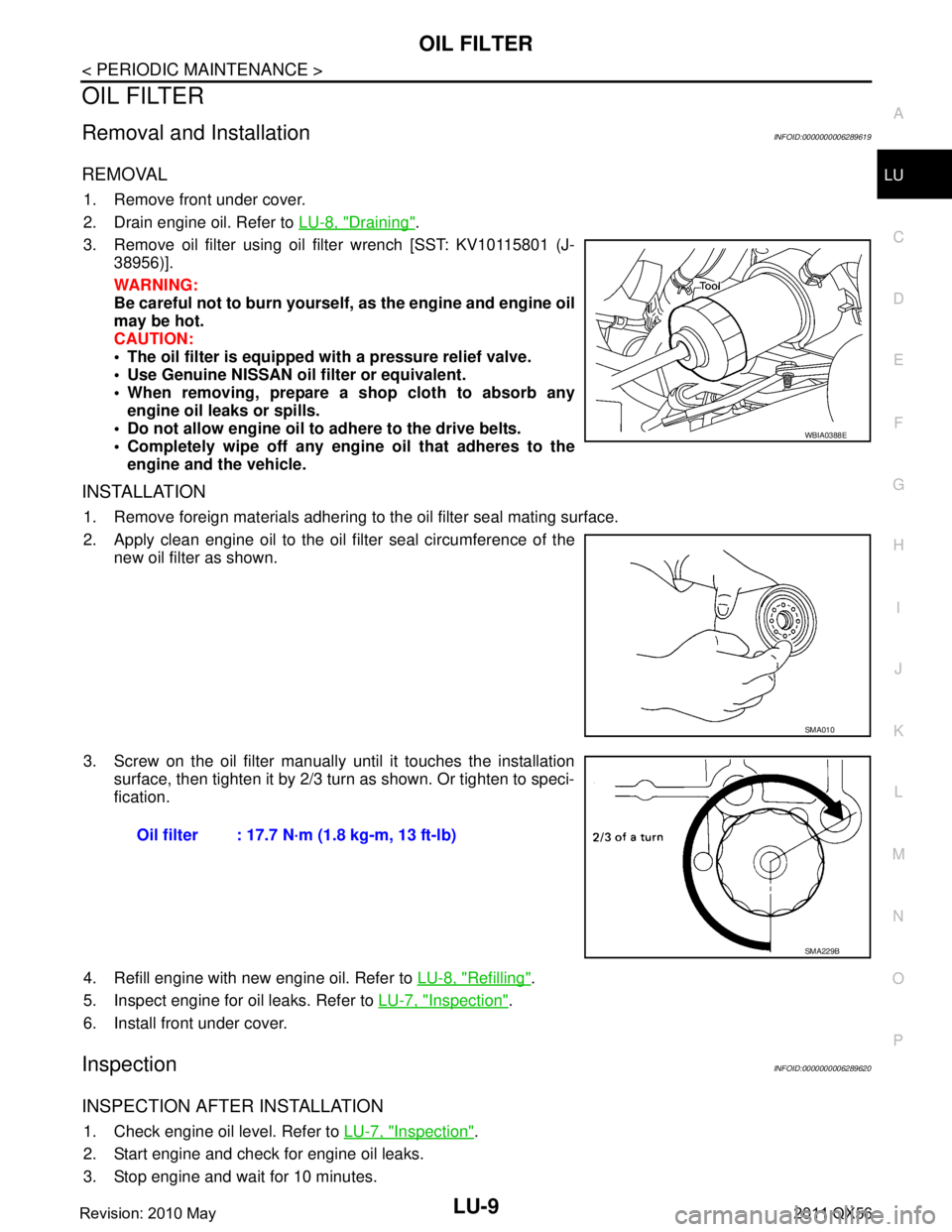
3. Remove oil filter using oil filter wrench [SST: KV10115801 (J- 38956)].
WARNING:
Be careful not to burn yourself, as the engine and engine oil
may be hot.
CAUTION:
The oil filter is equipped with a pressure relief valve.
Use Genuine NISSAN oil filter or equivalent.
When removing, prepare a s hop cloth to absorb any
engine oil leaks or spills.
Do not allow engine oil to adhere to the drive belts.
Completely wipe off any engine oil that adheres to the engine and the vehicle.
INSTALLATION
1. Remove foreign materials adhering to the oil filter seal mating surface.
2. Apply clean engine oil to the oil filter seal circumference of the
new oil filter as shown.
3. Screw on the oil filter manually until it touches the installation surface, then tighten it by 2/3 turn as shown. Or tighten to speci-
fication.
4. Refill engine with new engine oil. Refer to LU-8, "
Refilling".
5. Inspect engine for oil leaks. Refer to LU-7, "
Inspection".
6. Install front under cover.
InspectionINFOID:0000000006289620
INSPECTION AFTER INSTALLATION
1. Check engine oil level. Refer to LU-7, "Inspection".
2. Start engine and check for engine oil leaks.
3. Stop engine and wait for 10 minutes.
WBIA0388E
SMA010
Oil filter : 17.7 N·m (1.8 kg-m, 13 ft-lb)
SMA229B
Revision: 2010 May2011 QX56