2011 INFINITI QX56 ABS
[x] Cancel search: ABSPage 690 of 5598

CORROSION PROTECTIONBRM-15
< REMOVAL AND INSTALLATION >
C
DE
F
G H
I
J
L
M A
B
BRM
N
O P
REMOVAL AND INSTALLATION
CORROSION PROTECTION
DescriptionINFOID:0000000006248490
To provide improved corrosion prevention, the follo wing anti-corrosive measures have been implemented in
NISSAN production plants. When repairing or replacing body panels, it is necessary to use the same anti-cor-
rosive measures.
Anti-Corrosive Precoated Steel (Galvannealed Steel)
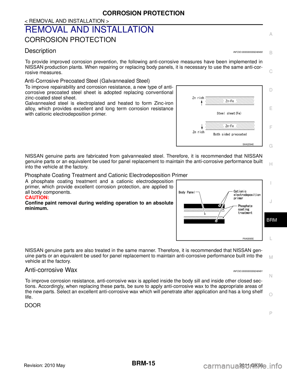
To improve repairability and corrosi on resistance, a new type of anti-
corrosive precoated steel sheet is adopted replacing conventional
zinc-coated steel sheet.
Galvannealed steel is electroplated and heated to form Zinc-iron
alloy, which provides excellent and long term corrosion resistance
with cationic electrodeposition primer.
NISSAN genuine parts are fabricated from galvannealed steel. Therefore, it is recommended that NISSAN
genuine parts or an equivalent be used for panel replacem ent to maintain the anti-corrosive performance built
into the vehicle at the factory.
Phosphate Coating Treatment and Cationic Electrodeposition Primer
A phosphate coating treatment and a cationic electrodeposition
primer, which provide excellent corrosion protection, are applied to
all body components.
CAUTION:
Confine paint removal during we lding operation to an absolute
minimum.
NISSAN genuine parts are also treated in the same manner. Therefore, it is recommended that NISSAN gen-
uine parts or an equivalent be used for panel replacement to maintain anti-corrosive performance built into the
vehicle at the factory.
Anti-corrosive WaxINFOID:0000000006248491
To improve corrosion resistance, anti-corrosive wax is applied inside the body sill and inside other closed sec-
tions. Accordingly, when replacing these parts, be sure to apply anti-corrosive wax to the appropriate areas of
the new parts. Select an excellent anti-corrosive wax which will penetrate after application and has a long shelf
life.
DOOR
SIIA2294E
PIIA0095E
Revision: 2010 May2011 QX56
Page 733 of 5598

BRM-58
< SERVICE DATA AND SPECIFICATIONS (SDS)
LOCATION OF PLASTIC PARTS
LOCATION OF PLASTIC PARTS
Precautions for PlasticsINFOID:0000000006248513
CAUTION:
When repairing and painting a portion of the body adjacent to plastic parts, consider their characteristics (influence of heatand solvent) and remove them if necessary or take suitable measures to protect them.
Plastic parts should be repaired and painted using methods suiting the materials
, characteristics.
Abbre-
viation Material name Heat resisting
temperature °C ( °F) Resistance to gasoline and
solvents Other cautions
PE Polyethylene 60 (140) Gasoline and most solvents are
harmless if applied for a very
short time (wipe out quickly).Flammable
ABS Acrylonitrile Butadiene Styrene 80 (176) Avoid gasoline and solvents. —
EPM/
EPDM Ethylene Propylene (Diene) co-
polymer
80 (176)Gasoline and most solvents are
harmless if applied for a very
short time (wipe out quickly). Flammable
PS Polystyrene 80 (176) Avoid solvents. Flammable
PVC Poly Vinyl Chloride 80 (176) Gasoline and most solvents are
harmless if applied for a very
short time (wipe out quickly).Poisonous gas is emitted
when burned.
TPO Thermoplastic Olefine 80 (176) ↑Flammable
AAS Acrylonitrile Acrylic Styrene 85 (185) Avoid gasoline and solvents. —
PMMA Poly Methyl Methacrylate 85 (185) ↑—
EVAC Ethylene Vinyl Acetate 90 (194) ↑—
PP Polypropylene 90 (194) Gasoline and most solvents are
harmless if applied for a very
short time (wipe out quickly).Flammable, avoid bat-
tery acid.
PUR Polyurethane 90 (194) Avoid gasoline and solvents. —
UP Unsaturated Polyester 90 (194) ↑Flammable
ASA Acrylonitrile Styrene Acrylate 100 (212) ↑Flammable
PPE Poly Phenylene Ether 110 (230) ↑—
TPU Thermoplastic Urethane 110 (230) ↑—
PBT+
PC Poly Butylene Terephthalate +
Polycarbonate
120 (248)
↑Flammable
PC Polycarbonate 120 (248) ↑—
POM Poly Oxymethylene 120 (248) ↑Avoid battery acid.
PA Polyamide 140 (284) ↑Avoid immersing in wa-
ter.
PBT Poly Butylene Terephthalate 140 (284) ↑—
PAR Polyarylate 180 (356) ↑—
PET Polyethylene terephthalate 180 (356) ↑—
PEI Polyetherimide 200 (392) ↑—
Revision: 2010 May2011 QX56
Page 734 of 5598

LOCATION OF PLASTIC PARTSBRM-59
< SERVICE DATA AND SPECIFICATIONS (SDS)
C
DE
F
G H
I
J
L
M A
B
BRM
N
O P
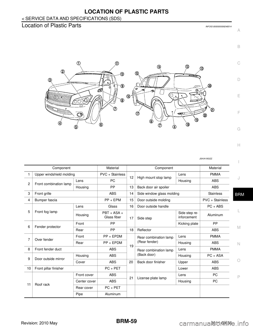
Location of Plastic PartsINFOID:0000000006248514
Component Material Component Material
1 Upper windshield molding PVC + Stainless 12 High mount stop lampLens PMMA
2 Front combination lamp Lens PC Housing ABS
Housing PP 13 Back door air spoiler ABS
3 Front grille ABS 14 Side window glass molding Stainless
4 Bumper fascia PP + EPM 15 Door outside molding PVC + Stainless
5 Front fog lamp Lens Glass 16 Door outside handle PC + ABS
Housing
PBT + ASA +
Glass fiber 17 Side step Side step re-
inforcement
Aluminum
6 Fender protector Front PP Kicking plate PP
Rear PP 18 Reflector ABS
7 Over fender Front PP + EPDM
19Rear combination lamp
(Rear fender)
Lens PMMA
Rear PP + EPDM Housing ABS
8 Front fender duct ABS Rear combination lamp
(Back door)Lens PMMA
9 Door outside mirror Housing ABS Housing PC + ASA
Cover ABS 20 Back door finisher Upper ABS
10 Front pillar finisher PC + PET Lower ABS
11 R o o f r a c k Front cover ABS
21 License plate lampLens PC
Center cover ABS Housing PC
Rear cover PC + PET
Pipe Aluminum
JSKIA1953ZZ
Revision: 2010 May2011 QX56
Page 735 of 5598

BRM-60
< SERVICE DATA AND SPECIFICATIONS (SDS)
LOCATION OF PLASTIC PARTS
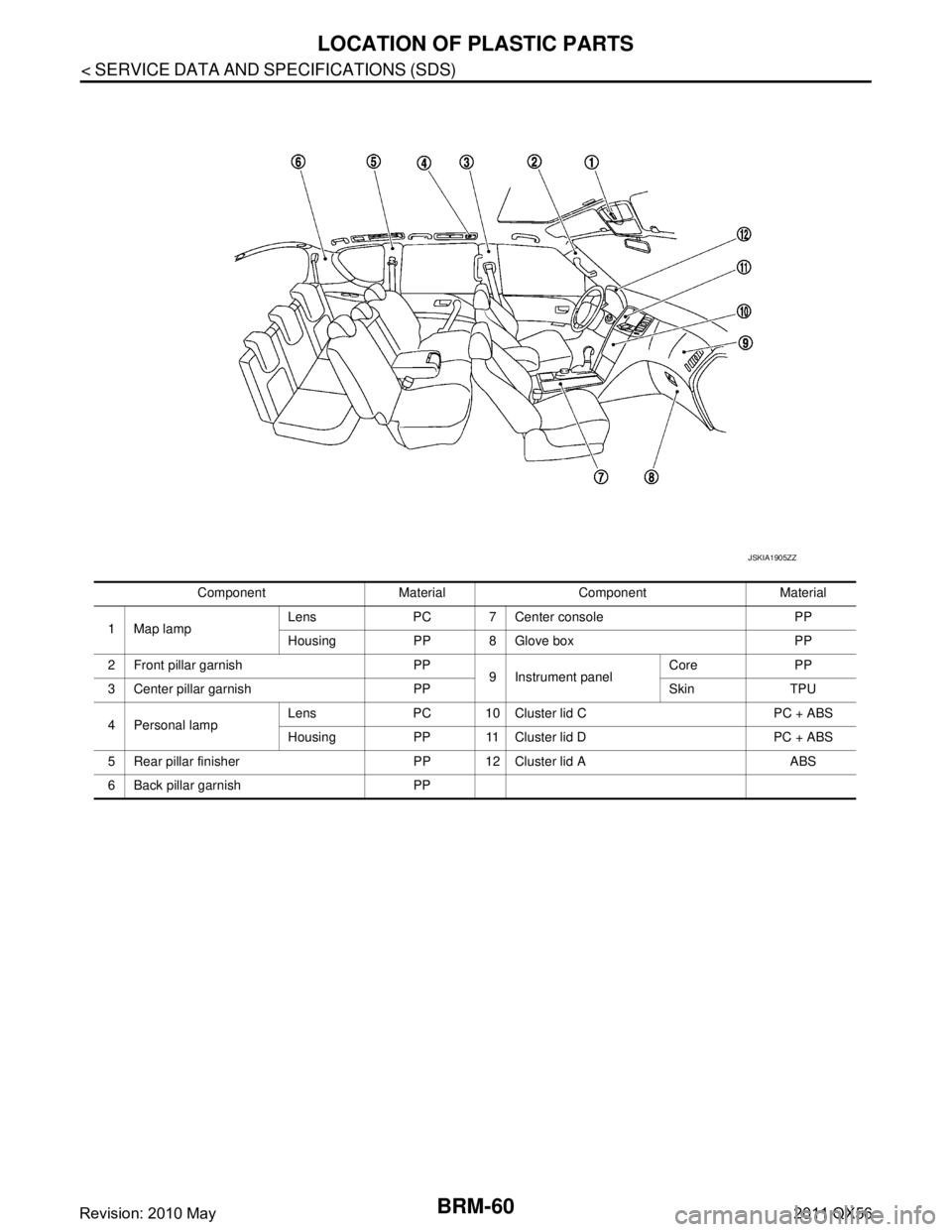
Component Material Component Material
1Map lamp Lens PC 7 Center console PP
Housing PP 8 Glove box PP
2 Front pillar garnish PP 9 Instrument panelCore PP
3 Center pillar garnish PP Skin TPU
4Personal lamp Lens PC 10 Cluster lid C PC + ABS
Housing PP 11 Cluster lid D PC + ABS
5 Rear pillar finisher PP 12 Cluster lid A ABS
6 Back pillar garnish PP
JSKIA1905ZZ
Revision: 2010 May2011 QX56
Page 737 of 5598

CCS-2
WIRING DIAGRAM .....................................57
INTELLIGENT CRUISE CONTROL ............... ...57
Wiring Diagram .................................................... ...57
BASIC INSPECTION ...................................69
DIAGNOSIS AND REPAIR WORK FLOW ..... ...69
Work Flow ............................................................ ...69
ADDITIONAL SERVICE WHEN REPLACING
ICC SENSOR .....................................................
71
Description ........................................................... ...71
Work Procedure ......................................................71
LASER BEAM AIMING ADJUSTMENT ............72
Description ........................................................... ...72
Work Procedure (Preparation) ................................72
Work Procedure (Setting The ICC Target Board) ...72
Work Procedure (Laser Beam Aiming Adjustment)
...
75
ACTION TEST ...................................................77
Description ........................................................... ...77
Work Procedure (Vehicle-To-Vehicle Distance
Control Mode) .........................................................
77
Work Procedure [Conventional (Fixed Speed)
Cruise Control Mode] ..............................................
80
DTC/CIRCUIT DIAGNOSIS ...................... ...83
C1A00 CONTROL UNIT ................................. ...83
ADAS CONTROL UNIT ......................................... ...83
ADAS CONTROL UNIT : DTC Logic ......................83
ADAS CONTROL UNIT : Diagnosis Procedure ......83
ICC SENSOR ......................................................... ...83
ICC SENSOR : DTC Logic .....................................83
ICC SENSOR : Diagnosis Procedure .....................83
C1A01 POWER SUPPLY CIRCUIT 1, C1A02
POWER SUPPLY CIRCUIT 2 ............................
85
ADAS CONTROL UNIT ......................................... ...85
ADAS CONTROL UNIT : DTC Logic ......................85
ADAS CONTROL UNIT : Diagnosis Procedure ......85
ICC SENSOR ......................................................... ...85
ICC SENSOR : DTC Logic .....................................85
ICC SENSOR : Diagnosis Procedure .....................86
C1A03 VEHICLE SPEED SENSOR ..................87
DTC Logic ............................................................ ...87
Diagnosis Procedure ..............................................87
C1A04 ABS/TCS/VDC SYSTEM .......................89
DTC Logic ............................................................ ...89
Diagnosis Procedure ..............................................89
C1A05 BRAKE SW/STOP LAMP SW ...............90
DTC Logic ............................................................ ...90
Diagnosis Procedure ..............................................90
Component Inspection (ICC Brake Switch) ......... ...93
Component Inspection (Stop Lamp Switch) ............93
C1A06 OPERATION SW ...................................94
DTC Logic ............................................................ ...94
Diagnosis Procedure ...............................................94
Component Inspection ............................................95
C1A12 LASER BEAM OFF CENTER ...............96
ADAS CONTROL UNIT .......................................... ...96
ADAS CONTROL UNIT : DTC Logic ......................96
ADAS CONTROL UNIT : Diagnosis Procedure ......96
ICC SENSOR .......................................................... ...96
ICC SENSOR : DTC Logic ......................................96
ICC SENSOR : Diagnosis Procedure .....................96
C1A13 STOP LAMP RELAY .............................97
DTC Logic ............................................................ ...97
Diagnosis Procedure ...............................................97
Component Inspection ..........................................102
C1A14 ECM ......................................................103
DTC Logic ............................................................ .103
Diagnosis Procedure .............................................103
C1A15 GEAR POSITION .................................104
Description ........................................................... .104
DTC Logic .............................................................104
Diagnosis Procedure .............................................104
C1A16 RADAR STAIN ................................... ..106
ADAS CONTROL UNIT .......................................... .106
ADAS CONTROL UNIT : DTC Logic ....................106
ADAS CONTROL UNIT : Diagnosis Procedure ....106
ICC SENSOR .......................................................... .106
ICC SENSOR : DTC Logic ....................................106
ICC SENSOR : Diagnosis Procedure ...................107
C1A17 ICC SENSOR ........................................108
DTC Logic ............................................................ .108
Diagnosis Procedure .............................................108
C1A18 LASER AIMING INCMP .......................109
ADAS CONTROL UNIT .......................................... .109
ADAS CONTROL UNIT : DTC Logic ....................109
ADAS CONTROL UNIT : Diagnosis Procedure ....109
ICC SENSOR .......................................................... .109
ICC SENSOR : DTC Logic ....................................109
ICC SENSOR : Diagnosis Procedure ...................110
C1A21 UNIT HIGH TEMP .................................111
ADAS CONTROL UNIT .......................................... .111
ADAS CONTROL UNIT : DTC Logic ....................111
ADAS CONTROL UNIT : Diagnosis Procedure ....111
ICC SENSOR .......................................................... .111
ICC SENSOR : DTC Logic ....................................111
Revision: 2010 May2011 QX56
Page 744 of 5598
![INFINITI QX56 2011 Factory Service Manual
CCS
COMPONENT PARTSCCS-9
< SYSTEM DESCRIPTION > [ICC]
C
D
E
F
G H
I
J
K L
M B
N P A
SYSTEM DESCRIPTION
COMPONENT PARTS
Component Parts LocationINFOID:0000000006224265
1. ICC steering switch 2. Inform INFINITI QX56 2011 Factory Service Manual
CCS
COMPONENT PARTSCCS-9
< SYSTEM DESCRIPTION > [ICC]
C
D
E
F
G H
I
J
K L
M B
N P A
SYSTEM DESCRIPTION
COMPONENT PARTS
Component Parts LocationINFOID:0000000006224265
1. ICC steering switch 2. Inform](/manual-img/42/57033/w960_57033-743.png)
CCS
COMPONENT PARTSCCS-9
< SYSTEM DESCRIPTION > [ICC]
C
D
E
F
G H
I
J
K L
M B
N P A
SYSTEM DESCRIPTION
COMPONENT PARTS
Component Parts LocationINFOID:0000000006224265
1. ICC steering switch 2. Information display, ICC system warning lamp, IBA OFF indicator
lamp, buzzer
(On the combination meter)3. BCM
Refer to BCS-4, "
BODY CONTROL
SYSTEM : Compon ent Parts Loca-
tion"
4. Transfer control unit
Refer to DLN-10, "
Component Parts
Location"
5. ICC brake hold relay 6. ECM
Refer to EC-16, "
Component Parts
Location"
7. ICC sensor 8. TCM
Refer to TM-10, "
A/T CONTROL
SYSTEM : Compon ent Parts Loca-
tion"
9. ABS actuator and electric unit (con-
trol unit)
Refer to BRC-10, "
Component Parts
Location"
10. Stop lamp switch 11. ICC brake switch 12. IBA OFF switch
JSOIA0362ZZ
Revision: 2010 May2011 QX56
Page 745 of 5598
![INFINITI QX56 2011 Factory Service Manual
CCS-10
< SYSTEM DESCRIPTION >[ICC]
COMPONENT PARTS
Component Description
INFOID:0000000006224266
× : Applicable
13. Steering angle sensor
Refer to BRC-10, "
Component Parts
Location"
14. ADAS cont INFINITI QX56 2011 Factory Service Manual
CCS-10
< SYSTEM DESCRIPTION >[ICC]
COMPONENT PARTS
Component Description
INFOID:0000000006224266
× : Applicable
13. Steering angle sensor
Refer to BRC-10, "
Component Parts
Location"
14. ADAS cont](/manual-img/42/57033/w960_57033-744.png)
CCS-10
< SYSTEM DESCRIPTION >[ICC]
COMPONENT PARTS
Component Description
INFOID:0000000006224266
× : Applicable
13. Steering angle sensor
Refer to BRC-10, "
Component Parts
Location"
14. ADAS control unit
Refer to DAS-13, "
Component Parts
Location"
A. Back side of engine room (RH) B. Front bumper (center) C. Upper side of brake pedal
D. Under side of inst rument lower driver
panel
Component Function
Description
Vehicle-to-vehicle distance control mode
Conventional (fixed speed) cruise control mode Intelligent Brake Assist (IBA)
Brake Assist (with preview function)
ADAS control unit ×××× ADAS control unit calculates a target distance between vehicles
and a target speed, based on signals received from each sensor
and switch to transmit an engine torque command value to ECM
and a brake fluid pres sure control signal to ABS actuator and
electric unit (control unit) via CAN communication
ADAS control unit transmits buzzer output signal to combination
meter via CAN communication
ICC sensor ×××× ICC sensor detects light reflected from a vehicle ahead by irra-
diating laser forward and calculates a distance from the vehicle
ahead and a relative speed, based on the detected signal
ICC sensor transmits the presence/absence of vehicle ahead and the distance from the vehicle to ADAS control unit via ITS
communication
ECM ×××× ECM transmits the accelerator pedal position signal, ICC brake
switch signal, stop lamp switch signal, ICC steering switch sig-
nal, etc. to ADAS control unit via CAN communication
ECM controls the electric throttle control actuator based on the engine torque demand received from the ADAS control unit via
CAN communication
ABS actuator and electric unit
(control unit) ×××× ABS actuator and electric unit (control unit) transmits the vehicle
speed signal (wheel speed), stop lamp signal and VDC/TCS/
ABS system operation condition to ADAS control unit via CAN
communication
ABS actuator and electric unit (control unit) controls the brake, based on a brake fluid pressure control signal received from the
ADAS control unit via CAN communication
BCM ×BCM transmits the front wiper request signal to ADAS control unit
via CAN communication
TCM ××TCM transmits the signal related to A/T control to ADAS control
unit via CAN communication
Revision: 2010 May2011 QX56
Page 746 of 5598
![INFINITI QX56 2011 Factory Service Manual
CCS
COMPONENT PARTSCCS-11
< SYSTEM DESCRIPTION > [ICC]
C
D
E
F
G H
I
J
K L
M B
N P A
NOTE:
Only IBA system uses
Combination meter ××××Performs the following operations using the signals received INFINITI QX56 2011 Factory Service Manual
CCS
COMPONENT PARTSCCS-11
< SYSTEM DESCRIPTION > [ICC]
C
D
E
F
G H
I
J
K L
M B
N P A
NOTE:
Only IBA system uses
Combination meter ××××Performs the following operations using the signals received](/manual-img/42/57033/w960_57033-745.png)
CCS
COMPONENT PARTSCCS-11
< SYSTEM DESCRIPTION > [ICC]
C
D
E
F
G H
I
J
K L
M B
N P A
NOTE:
Only IBA system uses
Combination meter ××××Performs the following operations using the signals received from
the ADAS control unit via the CAN communication
Displays the ICC system operation status using the meter dis-
play signal
Illuminates the ICC system warning lamp using the ICC warning
lamp signal
Illuminates the IBA OFF indicator lamp using the IBA OFF indi- cator lamp signal
Operates the buzzer (ICC warning chime) using the buzzer out- put signal
ICC steering switch ×× ICC steering switch allows the ON/OFF of the Intelligent Cruise
Control and the settings of a vehicle speed and distance be-
tween vehicles
ICC steering switch signal is transmitted to ECM. ECM transmits the signal to the ADAS control unit via CAN communication
ICC brake switch ×××× ICC brake switch is turned OFF and stop lamp switch is turned
ON, when depressing the brake pedal
ICC brake switch signal is input to ECM. These signals are transmitted from ECM to ADAS control unit via CAN communi-
cation
Stop lamp switch signal is in put to ECM and ABS actuator and
electric unit (control unit). These signals are transmitted from
ECM and ABS actuator and electric unit (control unit) to ADAS
control unit via CAN communication
Stop lamp switch
××××
ICC brake hold relay ××ICC brake hold relay activates the stop lamp by ICC brake hold re-
lay drive signal (stop lamp drive signal) outputted by the ADAS
control unit
Transfer control unit ××××Transfer control unit transmits a mode selection state of 4WD shift
switch to the ADAS control unit via CAN communication
IBA OFF switch ×
NoteIBA OFF switch signal is input to the ADAS control unit
Steering angle sensor ×Measures the rotation amount, rotation speed, and rotation direc-
tion of steering wheel, and then transmits them to ADAS control
unit via CAN communication
Component
Function
Description
Vehicle-to-vehicle distance control mode
Conventional (fixed speed) cruise control mode Intelligent Brake Assist (IBA)
Brake Assist (with preview function)
Revision: 2010 May2011 QX56