2011 INFINITI QX56 body int
[x] Cancel search: body intPage 4406 of 5598
![INFINITI QX56 2011 Factory Service Manual
SCS-46
< REMOVAL AND INSTALLATION >[HBMC]
HYDRAULIC BODY-MOTION CONTROL SYSTEM
3. Remove lower side pipe (A) of rear shock absorber RH.
4. Remove pipe (A) from left side rear joint (B).
5. Remove mou INFINITI QX56 2011 Factory Service Manual
SCS-46
< REMOVAL AND INSTALLATION >[HBMC]
HYDRAULIC BODY-MOTION CONTROL SYSTEM
3. Remove lower side pipe (A) of rear shock absorber RH.
4. Remove pipe (A) from left side rear joint (B).
5. Remove mou](/manual-img/42/57033/w960_57033-4405.png)
SCS-46
< REMOVAL AND INSTALLATION >[HBMC]
HYDRAULIC BODY-MOTION CONTROL SYSTEM
3. Remove lower side pipe (A) of rear shock absorber RH.
4. Remove pipe (A) from left side rear joint (B).
5. Remove mounting bolts of bracket of rear tube assembly B.
6. Remove mounting bolts of bracket of rear left brake hose, and
then free hose.
7. Remove rear tube assembly B from the vehicle.
8. Perform inspection after removal. Refer to SCS-46, "
REAR
TUBE ASSEMBLY : Inspection".
INSTALLATION
Note the following, and install in the reverse order of removal.
Apply genuine NISSAN hydraulic suspension fluid to O-ring.
Check connection portion of each piping for dirt or dust.
REAR TUBE ASSEMBLY : InspectionINFOID:0000000006256034
INSPECTION AFTER REMOVAL
O-ring must be free of scratches and damage.
Pipe and tube must be free of scratches and damage.
INSPECTION AFTER INSTALLATION
Check oil leakage, twists, deformation, contact with other parts, and loose connections.
ADJUSTMENT AFTER INSTALLATION
Perform air bleeding. Refer to SCS-18, "Work Procedure".
JSEIA0212ZZ
JSEIA0204ZZ
Revision: 2010 May2011 QX56
Page 4460 of 5598

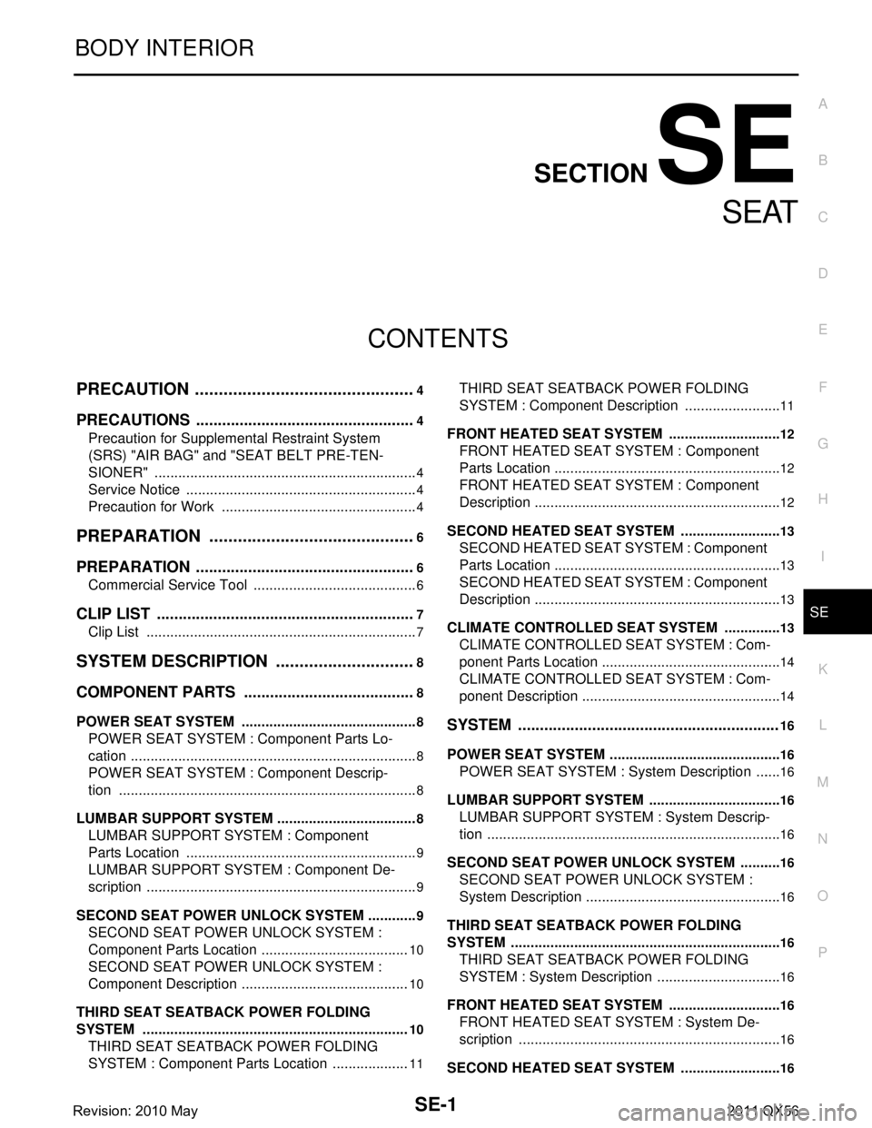
SE-1
BODY INTERIOR
C
DE
F
G H
I
K L
M
SECTION SE
A
B
SE
N
O P
CONTENTS
SEAT
PRECAUTION ................ ...............................4
PRECAUTIONS .............................................. .....4
Precaution for Supplemental Restraint System
(SRS) "AIR BAG" and "SEAT BELT PRE-TEN-
SIONER" ............................................................. ......
4
Service Notice ...........................................................4
Precaution for Work ..................................................4
PREPARATION ............................................6
PREPARATION .............................................. .....6
Commercial Service Tool .................................... ......6
CLIP LIST ............................................................7
Clip List ............................................................... ......7
SYSTEM DESCRIPTION ..............................8
COMPONENT PARTS ................................... .....8
POWER SEAT SYSTEM .............................................8
POWER SEAT SYSTEM : Component Parts Lo-
cation ................................................................... ......
8
POWER SEAT SYSTEM : Component Descrip-
tion ...................................................................... ......
8
LUMBAR SUPPORT SYSTEM .............................. ......8
LUMBAR SUPPORT SYSTEM : Component
Parts Location ..................................................... ......
9
LUMBAR SUPPORT SYSTEM : Component De-
scription .....................................................................
9
SECOND SEAT POWER UNLOCK SYSTEM ....... ......9
SECOND SEAT POWER UNLOCK SYSTEM :
Component Parts Location ......................................
10
SECOND SEAT POWER UNLOCK SYSTEM :
Component Description ...........................................
10
THIRD SEAT SEATBACK POWER FOLDING
SYSTEM ................................................................ ....
10
THIRD SEAT SEATBACK POWER FOLDING
SYSTEM : Component Parts Location ....................
11
THIRD SEAT SEATBACK POWER FOLDING
SYSTEM : Component Description ..................... ....
11
FRONT HEATED SEAT SYSTEM ......................... ....12
FRONT HEATED SEAT SYSTEM : Component
Parts Location ..........................................................
12
FRONT HEATED SEAT SYSTEM : Component
Description ...............................................................
12
SECOND HEATED SEAT SYSTEM ...................... ....13
SECOND HEATED SEAT SYSTEM : Component
Parts Location ..........................................................
13
SECOND HEATED SEAT SYSTEM : Component
Description ...............................................................
13
CLIMATE CONTROLLED SEAT SYSTEM ...............13
CLIMATE CONTROLLED SEAT SYSTEM : Com-
ponent Parts Location .......................................... ....
14
CLIMATE CONTROLLED SEAT SYSTEM : Com-
ponent Description ...................................................
14
SYSTEM ............................................................16
POWER SEAT SYSTEM ....... .....................................16
POWER SEAT SYSTEM : Syst em Description .......16
LUMBAR SUPPORT SYSTEM .............................. ....16
LUMBAR SUPPORT SYSTEM : System Descrip-
tion ...........................................................................
16
SECOND SEAT POWER UNLOCK SYSTEM ...........16
SECOND SEAT POWER UNLOCK SYSTEM :
System Description .............................................. ....
16
THIRD SEAT SEATBACK POWER FOLDING
SYSTEM .....................................................................
16
THIRD SEAT SEATBACK POWER FOLDING
SYSTEM : System Description ............................ ....
16
FRONT HEATED SEAT SYSTEM ......................... ....16
FRONT HEATED SEAT SYSTEM : System De-
scription ...................................................................
16
SECOND HEATED SEAT SYSTEM ...................... ....16
Revision: 2010 May2011 QX56
Page 4463 of 5598

SE-4
< PRECAUTION >
PRECAUTIONS
PRECAUTION
PRECAUTIONS
Precaution for Supplemental Restraint System (SRS) "AIR BAG" and "SEAT BELT
PRE-TENSIONER"
INFOID:0000000006237842
The Supplemental Restraint System such as “A IR BAG” and “SEAT BELT PRE-TENSIONER”, used along
with a front seat belt, helps to reduce the risk or severi ty of injury to the driver and front passenger for certain
types of collision. This system includes seat belt switch inputs and dual stage front air bag modules. The SRS
system uses the seat belt switches to determine the front air bag deployment, and may only deploy one front
air bag, depending on the severity of a collision and w hether the front occupants are belted or unbelted.
Information necessary to service the system safely is included in the “SRS AIR BAG” and “SEAT BELT” of this
Service Manual.
WARNING:
• To avoid rendering the SRS inopera tive, which could increase the risk of personal injury or death in
the event of a collision that would result in air bag inflation, all maintenance must be performed by
an authorized NISS AN/INFINITI dealer.
Improper maintenance, including in correct removal and installation of the SRS, can lead to personal
injury caused by unintent ional activation of the system. For re moval of Spiral Cable and Air Bag
Module, see the “SRS AIR BAG”.
Do not use electrical test equipmen t on any circuit related to the SRS unless instructed to in this
Service Manual. SRS wiring harnesses can be identi fied by yellow and/or orange harnesses or har-
ness connectors.
PRECAUTIONS WHEN USING POWER TOOLS (AIR OR ELECTRIC) AND HAMMERS
WARNING:
When working near the Air Bag Diagnosis Sensor Unit or other Air Bag System sensors with the ignition ON or engine running, DO NOT use air or electric power tools or strike near the sensor(s)
with a hammer. Heavy vibration could activate the sensor(s) and deploy the air bag(s), possibly
causing serious injury.
When using air or electric power tools or hammers , always switch the ignition OFF, disconnect the
battery, and wait at least 3 minu tes before performing any service.
Service NoticeINFOID:0000000006217352
When removing or installing various parts, place a cloth or padding onto the vehicle body to prevent
scratches.
Handle trim, molding, instruments, grille, etc. carefull y during removing or installing. Be careful not to oil or
damage them.
Apply sealing compound where necessary when installing parts.
When applying sealing compound, be careful that t he sealing compound never protrudes from parts.
When replacing any metal parts (for example body outer panel, members, etc.), always take rust prevention
measures.
Precaution for WorkINFOID:0000000006217353
When removing or disassembling each component, be careful not to damage or deform it. If a component
may be subject to interference, al ways protect it with a shop cloth.
When removing (disengaging) components with a screwdriver or similar tool, always wrap the component
with a shop cloth or vinyl tape to protect it.
Protect the removed parts with a shop cloth and keep them.
Replace a deformed or damaged clip.
If a part is specified as a non-reusable part, always replace it with new one.
Always tighten bolts and nuts securely to the specified torque.
After reinstallation is complete, always check that each part works normally.
Follow the steps below to clean components.
- Water soluble foul: Dip a soft cloth into lukewarm water, and wring the water out of the cloth to wipe the fouled area.
Then rub with a soft and dry cloth.
Revision: 2010 May2011 QX56
Page 4559 of 5598

SE-100
< SYMPTOM DIAGNOSIS >
SQUEAK AND RATTLE TROUBLE DIAGNOSES
If the noise can be duplicated easily during the test drive, to help identify the source of the noise, try to dupli-
cate the noise with the vehicle stopped by doing one or all of the following:
1) Close a door.
2) Tap or push/pull around the area where the noise appears to be coming from.
3) Rev the engine.
4) Use a floor jack to recreate vehicle “twist”.
5) At idle, apply engine load (electrical load, half-cl utch on M/T models, drive position on A/T models).
6) Raise the vehicle on a hoist and hit a tire with a rubber hammer.
Drive the vehicle and attempt to duplicate the conditions the customer states exist when the noise occurs.
If it is difficult to duplicate the noise, drive the v ehicle slowly on an undulating or rough road to stress the
vehicle body.
CHECK RELATED SERVICE BULLETINS
After verifying the customer concern or symptom, chec k ASIST for Technical Service Bulletins (TSBs) related
to that concern or symptom.
If a TSB relates to the symptom, follo w the procedure to repair the noise.
LOCATE THE NOISE AND IDENTIFY THE ROOT CAUSE
1. Narrow down the noise to a general area. To help pi npoint the source of the noise, use a listening tool
(Chassis ear: J-39570, Engine ear and mechanics stethoscope).
2. Narrow down the noise to a more specific area and identify the cause of the noise by:
Removing the components in the area that is are suspected to be the cause of the noise.
Do not use too much force when removing clips and fasteners, otherwise clips and fastener can be broken
or lost during the repair, resulting in the creation of new noise.
Tapping or pushing/pulling the component that is are suspected to be the cause of the noise.
Do not tap or push/pull the component with excessive force, otherwise the noise will be eliminated only tem-
porarily.
Feeling for a vibration by hand by touching the component (s) that is are suspected to be the cause of the
noise.
Placing a piece of paper between components that are suspected to be the cause of the noise.
Looking for loose components and contact marks. Refer to SE-101, "
Inspection Procedure".
REPAIR THE CAUSE
If the cause is a loose component, tighten the component securely.
If the cause is insufficient clearance between components:
- Separate components by repositioning or loos ening and retightening the component, if possible.
- Insulate components with a suitable insulator such as urethane pads, foam blocks, felt cloth tape or ure-
thane tape. A Nissan Squeak and Rattle Kit (J-43980) is available through the authorized Nissan Parts
Department.
CAUTION:
Never use excessive force as many components are constructed of plastic and may be damaged.
NOTE:
Always check with the Parts Departm ent for the latest parts information.
The following materials are contained in the Nissan Squeak and Rattle Kit (J-43980). Each item can be
ordered separately as needed.
URETHANE PADS [1.5 mm (0.059 in) thick]
Insulates connectors, harness, etc.
76268-9E005: 100 ×135 mm (3.94 ×5.31 in)/76884-71L01: 60 ×85 mm (2.36 ×3.35 in)/76884-
71L02:15 ×25 mm (0.59 ×0.98 in)
INSULATOR (Foam blocks)
Insulates components from contact. Can be used to fill space behind a panel.
73982-9E000: 45 mm (1.77 in) thick, 50 ×50 mm (1.97 ×1.97 in)/73982-
50Y00: 10 mm (0.39 in) thick, 50 ×50 mm (1.97 ×1.97 in)
INSULATOR (Light foam block)
80845-71L00: 30 mm (1.18 in) thick, 30 ×50 mm (1.18 ×1.97in)
FELT CLOTHTAPE
Used to insulate where movement does not occu r. Ideal for instrument panel applications.
68370-4B000: 15 ×25 mm (0.59 ×0.98 in) pad/68239-13E00: 5 mm (0.20 in) wide tape roll
The following materials, not found in the kit, can also be used to repair squeaks and rattles.
UHMW (TEFLON) TAPE
Revision: 2010 May2011 QX56
Page 4608 of 5598

SEC-1
BODY EXTERIOR, DOORS, ROOF & VEHICLE SECURITY
C
D
E
F
G H
I
J
L
M
SECTION SEC
A
B
SEC
N
O P
CONTENTS
SECURITY CONTROL SYSTEM
WITH INTELLIGE NT KEY SYSTEM
PRECAUTION ................ ...............................
5
PRECAUTIONS .............................................. .....5
Precaution for Supplemental Restraint System
(SRS) "AIR BAG" and "SEAT BELT PRE-TEN-
SIONER" ............................................................. ......
5
Precaution Necessary for Steering Wheel Rota-
tion after Battery Disconnect .....................................
5
Precaution for Procedure without Cowl Top Cover ......6
SYSTEM DESCRIPTION ..............................7
COMPONENT PARTS ................................... .....7
Component Parts Location .................................. ......7
Component Description .............................................8
A/T Shift Selector (Detention Switch) ........................8
BCM ..........................................................................8
ECM ..........................................................................9
IPDM E/R ..................................................................9
NATS Antenna Amp. .................................................9
TCM ..........................................................................9
Combination Meter ....................................................9
Door Switch ...............................................................9
Hood Switch ..............................................................9
Inside Key Antenna ...................................................9
Intelligent Key ............................................................9
Push-button Ignition Switch .....................................10
Remote Keyless Entry Receiver .............................10
Security Indicator Lamp ..........................................10
Starter Control Relay ...............................................10
Starter Relay ...........................................................10
Steering Lock Relay ................................................10
Steering Lock Unit ...................................................10
Stop Lamp Switch ...................................................10
Transmission Range Switch ....................................10
Vehicle Information Display .....................................11
SYSTEM .............................................................12
INTELLIGENT KEY SYSTEM/ENGINE START
FUNCTION ............................................................. ....
12
INTELLIGENT KEY SYSTEM/ENGINE START
FUNCTION : System Diagram ................................
12
INTELLIGENT KEY SYSTEM/ENGINE START
FUNCTION : System Description ............................
12
INFINITI VEHICLE IMMOBILIZER SYSTEM-NATS ....14
INFINITI VEHICLE IMMOBILIZER SYSTEM-
NATS : System Diagram .........................................
15
INFINITI VEHICLE IMMOBILIZER SYSTEM-
NATS : System Description .....................................
15
VEHICLE SECURITY SYSTEM .................................17
VEHICLE SECURITY SYSTEM : System Dia-
gram .................................................................... ....
17
VEHICLE SECURITY SYSTEM : System Descrip-
tion ...........................................................................
18
DIAGNOSIS SYSTEM (BCM) ...........................21
COMMON ITEM ..................................................... ....21
COMMON ITEM : CONSULT-III Function (BCM -
COMMON ITEM) .....................................................
21
INTELLIGENT KEY ................................................ ....22
INTELLIGENT KEY : CONSULT-III Function
(BCM - INTELLIGENT KEY) ....................................
22
THEFT ALM ........................................................... ....26
THEFT ALM : CONSULT-III Function (BCM -
THEFT) ................................................................ ....
26
IMMU ...................................................................... ....27
IMMU : CONSULT-III Function (BCM - IMMU) ........27
DIAGNOSIS SYSTEM (IPDM E/R) ...................28
CONSULT-III Function (IPDM E/R) .........................28
ECU DIAGNOSIS INFORMATION ..............30
ECM, IPDM E/R, BCM .......................................30
List of ECU Reference ......................................... ....30
Revision: 2010 May2011 QX56
Page 4614 of 5598
![INFINITI QX56 2011 Factory Service Manual
COMPONENT PARTSSEC-7
< SYSTEM DESCRIPTION > [WITH INTELLIGENT KEY SYSTEM]
C
D
E
F
G H
I
J
L
M A
B
SEC
N
O P
SYSTEM DESCRIPTION
COMPONENT PARTS
Component Parts LocationINFOID:0000000006226151
1. Insid INFINITI QX56 2011 Factory Service Manual
COMPONENT PARTSSEC-7
< SYSTEM DESCRIPTION > [WITH INTELLIGENT KEY SYSTEM]
C
D
E
F
G H
I
J
L
M A
B
SEC
N
O P
SYSTEM DESCRIPTION
COMPONENT PARTS
Component Parts LocationINFOID:0000000006226151
1. Insid](/manual-img/42/57033/w960_57033-4613.png)
COMPONENT PARTSSEC-7
< SYSTEM DESCRIPTION > [WITH INTELLIGENT KEY SYSTEM]
C
D
E
F
G H
I
J
L
M A
B
SEC
N
O P
SYSTEM DESCRIPTION
COMPONENT PARTS
Component Parts LocationINFOID:0000000006226151
1. Inside key antenna (console) Refer to DLK-11, "
DOOR LOCK
SYSTEM :
ComponentPartsLocation". 2. A/T assembly
Refer to TM-10, "
A/T CONTROL
SYSTEM : Compon ent Parts Loca-
tion". 3. Push-button ignition switch
4. NATS antenna amp. 5. Inside key antenna (instrument cen- ter)
Refer to DLK-11, "
DOOR LOCK
SYSTEM :
ComponentPartsLocation". 6. IPDM E/R
Refer to PCS-4, "
Component Parts
Location".
7. ECM Refer to EC-16, "
Component Parts
Location"). 8. Horn 9. ABS actuator and electric unit (con-
trol unit)
Refer to BRC-10, "Component Parts
Location".
10. Stop lamp switch Refer to EC-16, "
Component Parts
Location". 11 . B C M
Refer to BCS-4, "
BODY CONTROL
SYSTEM : Compon ent Parts Loca-
tion". 12. Combination meter
Refer to MWI-6, "
METER SYSTEM :
Component Parts Location".
JMKIA5243ZZ
Revision: 2010 May2011 QX56
Page 4628 of 5598
![INFINITI QX56 2011 Factory Service Manual
DIAGNOSIS SYSTEM (BCM)SEC-21
< SYSTEM DESCRIPTION > [WITH INTELLIGENT KEY SYSTEM]
C
D
E
F
G H
I
J
L
M A
B
SEC
N
O P
DIAGNOSIS SYSTEM (BCM)
COMMON ITEM
COMMON ITEM : CONSULT-III Fu nction (BCM - COMMO INFINITI QX56 2011 Factory Service Manual
DIAGNOSIS SYSTEM (BCM)SEC-21
< SYSTEM DESCRIPTION > [WITH INTELLIGENT KEY SYSTEM]
C
D
E
F
G H
I
J
L
M A
B
SEC
N
O P
DIAGNOSIS SYSTEM (BCM)
COMMON ITEM
COMMON ITEM : CONSULT-III Fu nction (BCM - COMMO](/manual-img/42/57033/w960_57033-4627.png)
DIAGNOSIS SYSTEM (BCM)SEC-21
< SYSTEM DESCRIPTION > [WITH INTELLIGENT KEY SYSTEM]
C
D
E
F
G H
I
J
L
M A
B
SEC
N
O P
DIAGNOSIS SYSTEM (BCM)
COMMON ITEM
COMMON ITEM : CONSULT-III Fu nction (BCM - COMMON ITEM)INFOID:0000000006365349
APPLICATION ITEM
CONSULT-III performs the following functions via CAN communication with BCM.
SYSTEM APPLICATION
BCM can perform the following functions for each system.
NOTE:
It can perform the diagnosis modes except the following for all sub system selection items.
×: Applicable item
*: This item is indicated, but not used.
FREEZE FRAME DATA (FFD)
The BCM records the following vehicle condition at the time a particular DTC is detected, and displays on
CONSULT-III.
Diagnosis mode Function Description
Work Support Changes the setting for each system function.
Self Diagnostic Result Displays the diagnosis results judged by BCM. Refer to BCS-57, "
DTCIndex".
CAN Diag Support Monitor Monitors the reception status of CAN communication viewed from BCM. Refer to CONSULT-III opera-
tion manual.
Data Monitor The BCM input/output signals are displayed.
Active Test The signals used to activate each device are forcibly supplied from BCM.
Ecu Identification The BCM part number is displayed.
Configuration Read and save the vehicle specification.
Write the vehicle specification when replacing BCM.
System Sub system selection item Diagnosis mode
Work Support Data Monitor Active Test
Door lock DOOR LOCK ×××
Rear window defo gger REAR DEFOGGER ××
Warning chime BUZZER ××
Interior room lamp timer INT LAMP ×××
Exterior lamp HEAD LAMP ×××
Wiper and washer WIPER ×××
Turn signal and hazard warning lamps FLASHER ×××
— AIR CONDITONER* ××
Intelligent Key system
Engine start system INTELLIGENT KEY
×××
Combination switch COMB SW ×
Body control system BCM ×
IVIS IMMU ×××
Interior room lamp battery saver BATTERY SAVER ×××
Back door TRUNK ×
Vehicle security system THEFT ALM ×××
RAP system RETAINED PWR ×
Signal buffer system SIGNAL BUFFER ××
Revision: 2010 May2011 QX56
Page 4768 of 5598

COLLISION DIAGNOSISSR-5
< BASIC INSPECTION >
C
DE
F
G
I
J
K L
M A
B
SR
N
O P
BASIC INSPECTION
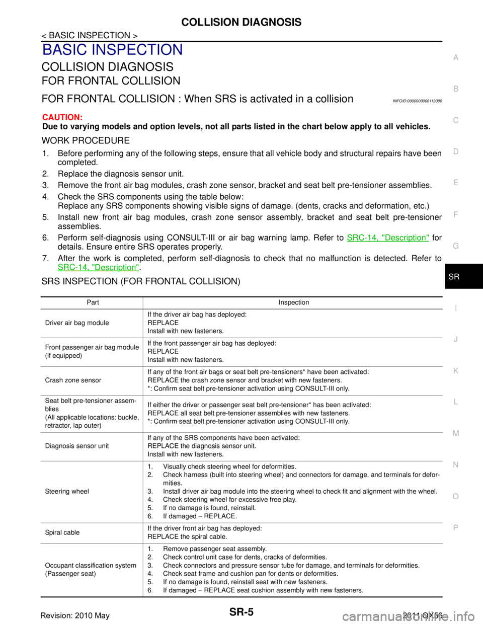
COLLISION DIAGNOSIS
FOR FRONTAL COLLISION
FOR FRONTAL COLLISION : When SR S is activated in a collisionINFOID:0000000006113080
CAUTION:
Due to varying models and option levels, not all parts listed in the chart below apply to all vehicles.
WORK PROCEDURE
1. Before performing any of the following steps, ensur e that all vehicle body and structural repairs have been
completed.
2. Replace the diagnosis sensor unit.
3. Remove the front air bag modules, crash zone sensor , bracket and seat belt pre-tensioner assemblies.
4. Check the SRS components using the table below: Replace any SRS components showing visible signs of damage. (dents, cracks and deformation, etc.)
5. Install new front air bag modules, crash zone sens or assembly, bracket and seat belt pre-tensioner
assemblies.
6. Perform self-diagnosis using CONSULT-III or air bag warning lamp. Refer to SRC-14, "
Description" for
details. Ensure entire SRS operates properly.
7. After the work is completed, perform self-diagnosis to check that no malfunction is detected. Refer to
SRC-14, "
Description".
SRS INSPECTION (FOR FRONTAL COLLISION)
Part Inspection
Driver air bag module If the driver air bag has deployed:
REPLACE
Install with new fasteners.
Front passenger air bag module
(if equipped) If the front passenger air bag has deployed:
REPLACE
Install with new fasteners.
Crash zone sensor If any of the front air bags or seat belt pre-tensioners* have been activated:
REPLACE the crash zone sensor and bracket with new fasteners.
*: Confirm seat belt pre-tensioner activation using CONSULT-III only.
Seat belt pre-tensioner assem-
blies
(All applicable locations: buckle,
retractor, lap outer) If either the driver or passenger seat belt pre-tensioner* has been activated:
REPLACE all seat belt pre-tensioner assemblies with new fasteners.
*: Confirm seat belt pre-tensioner activation using CONSULT-III only.
Diagnosis sensor unit If any of the SRS components have been activated:
REPLACE the diagnosis sensor unit.
Install with new fasteners.
Steering wheel 1. Visually check steering wheel for deformities.
2. Check harness (built into steering wheel) and connectors for damage, and terminals for defor-
mities.
3. Install driver air bag module into the steering wheel to check fit and alignment with the wheel.
4. Check steering wheel for excessive free play.
5. If no damage is found, reinstall.
6. If damaged − REPLACE.
Spiral cable If the driver front air bag has deployed:
REPLACE the spiral cable.
Occupant classification system
(Passenger seat) 1. Remove passenger seat assembly.
2. Check control unit case for dents, cracks of deformities.
3. Check connectors and pressure sensor tube for damage, and terminals for deformities.
4. Check seat frame and cushion pan for dents or deformities.
5. If no damage is found, reinstall seat with new fasteners.
6. If damaged
− REPLACE seat cushion assembly with new fasteners.
Revision: 2010 May2011 QX56