2011 INFINITI QX56 body int
[x] Cancel search: body intPage 4769 of 5598
SR-6
< BASIC INSPECTION >
COLLISION DIAGNOSIS
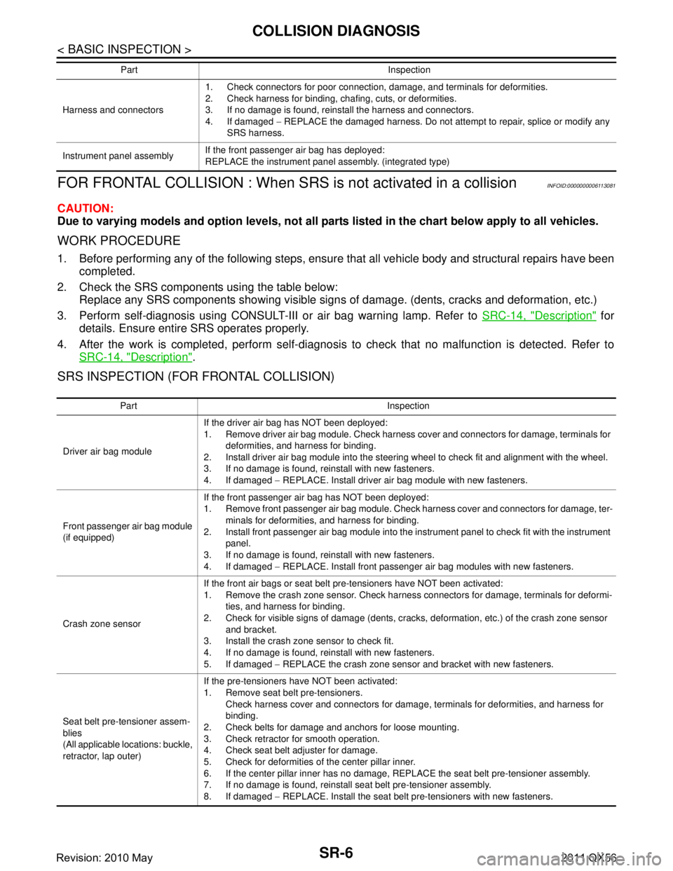
FOR FRONTAL COLLISION : When SRS is not activated in a collision
INFOID:0000000006113081
CAUTION:
Due to varying models and option levels, not all part s listed in the chart below apply to all vehicles.
WORK PROCEDURE
1. Before performing any of the following steps, ensur e that all vehicle body and structural repairs have been
completed.
2. Check the SRS components using the table below: Replace any SRS components showing visible signs of damage. (dents, cracks and deformation, etc.)
3. Perform self-diagnosis using CONSULT-III or air bag warning lamp. Refer to SRC-14, "
Description" for
details. Ensure entire SRS operates properly.
4. After the work is completed, perform self-diagnosis to check that no malfunction is detected. Refer to
SRC-14, "
Description".
SRS INSPECTION (FOR FRONTAL COLLISION)
Harness and connectors 1. Check connectors for poor connection, damage, and terminals for deformities.
2. Check harness for binding, chafing, cuts, or deformities.
3. If no damage is found, reinstall the harness and connectors.
4. If damaged
− REPLACE the damaged harness. Do not attempt to repair, splice or modify any
SRS harness.
Instrument panel assembly If the front passenger air bag has deployed:
REPLACE the instrument panel assembly. (integrated type)
Part Inspection
Part Inspection
Driver air bag module If the driver air bag has NOT been deployed:
1. Remove driver air bag module. Check harness cover and connectors for damage, terminals for
deformities, and harness for binding.
2. Install driver air bag module into the steering wheel to check fit and alignment with the wheel.
3. If no damage is found, reinstall with new fasteners.
4. If damaged − REPLACE. Install driver air bag module with new fasteners.
Front passenger air bag module
(if equipped) If the front passenger air bag has NOT been deployed:
1. Remove front passenger air bag module. Check harness cover and connectors for damage, ter-
minals for deformities, and harness for binding.
2. Install front passenger air bag module into the instrument panel to check fit with the instrument panel.
3. If no damage is found, reinstall with new fasteners.
4. If damaged − REPLACE. Install front passenger air bag modules with new fasteners.
Crash zone sensor If the front air bags or seat belt pre-tensioners have NOT been activated:
1. Remove the crash zone sensor. Check harness connectors for damage, terminals for deformi-
ties, and harness for binding.
2. Check for visible signs of damage (dents, cracks, deformation, etc.) of the crash zone sensor and bracket.
3. Install the crash zone sensor to check fit.
4. If no damage is found, reinstall with new fasteners.
5. If damaged − REPLACE the crash zone sensor and bracket with new fasteners.
Seat belt pre-tensioner assem-
blies
(All applicable locations: buckle,
retractor, lap outer) If the pre-tensioners have NOT been activated:
1. Remove seat belt pre-tensioners.
Check harness cover and connectors for damage , terminals for deformities, and harness for
binding.
2. Check belts for damage and anchors for loose mounting.
3. Check retractor for smooth operation.
4. Check seat belt adjuster for damage.
5. Check for deformities of the center pillar inner.
6. If the center pillar inner has no damage, REPLACE the seat belt pre-tensioner assembly.
7. If no damage is found, reinstall seat belt pre-tensioner assembly.
8. If damaged − REPLACE. Install the seat belt pre-tensioners with new fasteners.
Revision: 2010 May2011 QX56
Page 4770 of 5598
COLLISION DIAGNOSISSR-7
< BASIC INSPECTION >
C
DE
F
G
I
J
K L
M A
B
SR
N
O P
FOR SIDE AND ROLLOVER COLLISION
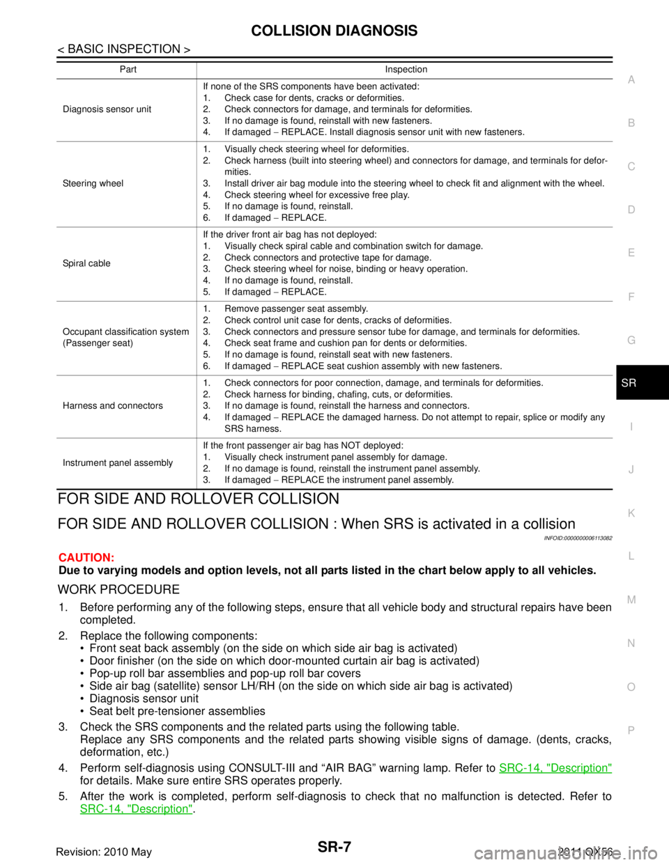
FOR SIDE AND ROLLOVER CO LLISION : When SRS is activated in a collision
INFOID:0000000006113082
CAUTION:
Due to varying models and option levels, not all parts listed in the chart below apply to all vehicles.
WORK PROCEDURE
1. Before performing any of the following steps, ensur e that all vehicle body and structural repairs have been
completed.
2. Replace the following components: Front seat back assembly (on the side on which side air bag is activated)
Door finisher (on the side on which door-mounted curtain air bag is activated)
Pop-up roll bar assemblies and pop-up roll bar covers
Side air bag (satellite) sensor LH/RH (on the side on which side air bag is activated)
Diagnosis sensor unit
Seat belt pre-tensioner assemblies
3. Check the SRS components and the related parts using the following table. Replace any SRS components and the related parts s howing visible signs of damage. (dents, cracks,
deformation, etc.)
4. Perform self-diagnosis using CONSULT-III and “AIR BAG” warning lamp. Refer to SRC-14, "
Description"
for details. Make sure entire SRS operates properly.
5. After the work is completed, perform self-diagnosis to check that no malfunction is detected. Refer to
SRC-14, "
Description".
Diagnosis sensor unit If none of the SRS components have been activated:
1. Check case for dents, cracks or deformities.
2. Check connectors for damage, and terminals for deformities.
3. If no damage is found, reinstall with new fasteners.
4. If damaged
− REPLACE. Install diagnosis sensor unit with new fasteners.
Steering wheel 1. Visually check steering wheel for deformities.
2. Check harness (built into steering wheel) and connectors for damage, and terminals for defor-
mities.
3. Install driver air bag module into the steering wheel to check fit and alignment with the wheel.
4. Check steering wheel for excessive free play.
5. If no damage is found, reinstall.
6. If damaged − REPLACE.
Spiral cable If the driver front air bag has not deployed:
1. Visually check spiral cable and combination switch for damage.
2. Check connectors and protective tape for damage.
3. Check steering wheel for noise, binding or heavy operation.
4. If no damage is found, reinstall.
5. If damaged
− REPLACE.
Occupant classification system
(Passenger seat) 1. Remove passenger seat assembly.
2. Check control unit case for dents, cracks of deformities.
3. Check connectors and pressure sensor tube for damage, and terminals for deformities.
4. Check seat frame and cushion pan for dents or deformities.
5. If no damage is found, reinstall seat with new fasteners.
6. If damaged
− REPLACE seat cushion assembly with new fasteners.
Harness and connectors 1. Check connectors for poor connection, damage, and terminals for deformities.
2. Check harness for binding, chafing, cuts, or deformities.
3. If no damage is found, reinstall the harness and connectors.
4. If damaged
− REPLACE the damaged harness. Do not attempt to repair, splice or modify any
SRS harness.
Instrument panel assembly If the front passenger air bag has NOT deployed:
1. Visually check instrument panel assembly for damage.
2. If no damage is found, reinstall the instrument panel assembly.
3. If damaged
− REPLACE the instrument panel assembly.
Part Inspection
Revision: 2010 May2011 QX56
Page 4771 of 5598
SR-8
< BASIC INSPECTION >
COLLISION DIAGNOSIS
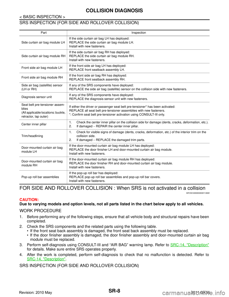
SRS INSPECTION (FOR SIDE AND ROLLOVER COLLISION)
FOR SIDE AND ROLLOVER COLLISION : When SRS is not activated in a collision
INFOID:0000000006113083
CAUTION:
Due to varying models and option levels, not all part s listed in the chart below apply to all vehicles.
WORK PROCEDURE
1. Before performing any of the following steps, ensur e that all vehicle body and structural repairs have been
completed.
2. Check the SRS components and the related parts using the following table. If the front seat back assembly is damaged, t he front seat back assembly must be replaced.
If the door finisher assembly is damaged, the door finisher assembly and door-mounted curtain air bag
module must be replaced.
3. Perform self-diagnosis using CONSULT-III and “AIR BAG” warning lamp. Refer to SRC-14, "
Description"
for details. Make sure entire SRS operates properly.
4. After the work is completed, perform self-diagnosis to check that no malfunction is detected. Refer to
SRC-14, "
Description".
SRS INSPECTION (FOR SIDE AND ROLLOVER COLLISION)
Part Inspection
Side curtain air bag module LH If the side curtain air bag LH has deployed:
REPLACE the side curtain air bag module LH.
Install with new fasteners.
Side curtain air bag module RH If the side curtain air bag RH has deployed:
REPLACE the side curtain air bag module RH.
Install with new fasteners.
Front side air bag module LH If the front side air bag LH has deployed:
REPLACE front seatback assembly LH.
Front side air bag module RH If the front side air bag RH has deployed:
REPLACE front seatback assembly RH.
Side air bag (satellite) sensor
(LH or RH) If any of the SRS components have deployed:
REPLACE the side air bag (satellite) sensor on the collision side with new fasteners.
Diagnosis sensor unit If any of the SRS components have deployed:
REPLACE the diagnosis sensor unit with new fasteners.
Seat belt pre-tensioner assem-
blies
(All applicable locations: buckle,
retractor, lap outer) If either the driver or passenger seat belt pre-tensioner* has been activated:
REPLACE all seat belt pre-tensioner assemblies with new fasteners.
*: Confirm seat belt pre-tensioner activation using CONSULT-III only.
Center inner pillar 1. Check the center inner pillar on the collision side for damage (dents, cracks, deformation, etc.).
2. If damaged
− REPAIR the center inner pillar.
Trim/headlining 1. Check for visible signs of damage (dents, cracks, deformation, etc.) of the interior trim on the
collision side.
2. If damaged − REPLACE the damaged trim parts.
Door-mounted curtain air bag
module LH If the door-mounted curtain air bag module LH has deployed:
REPLACE the door finisher LH and door-mounted curtain air bag module.
Install with new fasteners.
Door-mounted curtain air bag
module RH If the door-mounted curtain air bag module RH has deployed:
REPLACE the door finisher RH and door-mounted curtain air bag module.
Install with new fasteners.
Pop-up roll bar assemblies If the pop-up roll bar has deployed:
REPLACE pop-up roll bar assemblies and pop-up roll bar covers.
Install with new fasteners.
Revision: 2010 May2011 QX56
Page 5038 of 5598
POWER STEERING OIL PUMPST-51
< REMOVAL AND INSTALLATION >
C
DE
F
H I
J
K L
M A
B
ST
N
O P
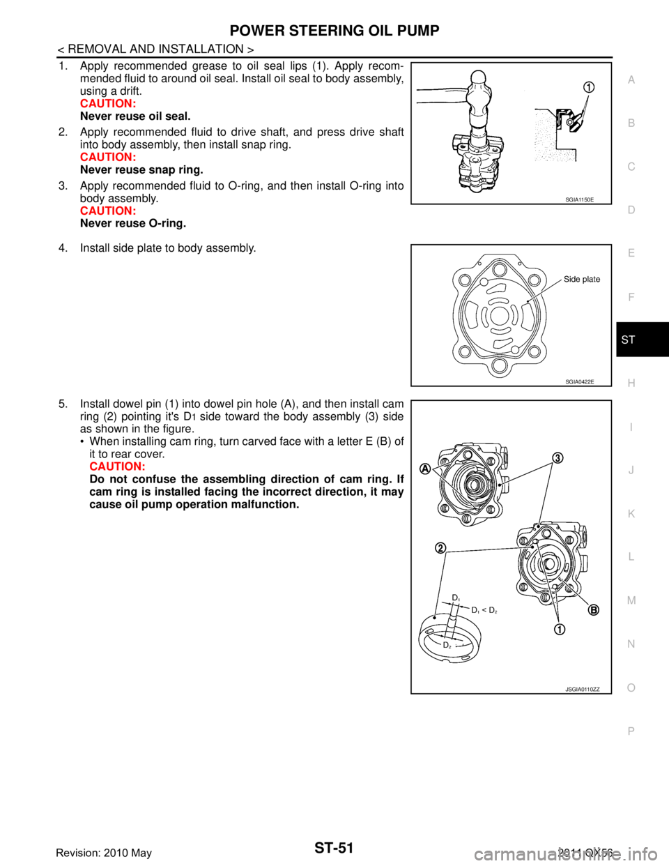
1. Apply recommended grease to oil seal lips (1). Apply recom- mended fluid to around oil seal. Install oil seal to body assembly,
using a drift.
CAUTION:
Never reuse oil seal.
2. Apply recommended fluid to drive shaft, and press drive shaft into body assembly, then install snap ring.
CAUTION:
Never reuse snap ring.
3. Apply recommended fluid to O-ring, and then install O-ring into body assembly.
CAUTION:
Never reuse O-ring.
4. Install side plate to body assembly.
5. Install dowel pin (1) into dowel pin hole (A), and then install cam ring (2) pointing it's D
1 side toward the body assembly (3) side
as shown in the figure.
When installing cam ring, turn carved face with a letter E (B) of
it to rear cover.
CAUTION:
Do not confuse the assembling direction of cam ring. If
cam ring is installed facing th e incorrect direction, it may
cause oil pump operation malfunction.
SGIA1150E
SGIA0422E
JSGIA0110ZZ
Revision: 2010 May2011 QX56
Page 5039 of 5598
ST-52
< REMOVAL AND INSTALLATION >
POWER STEERING OIL PUMP
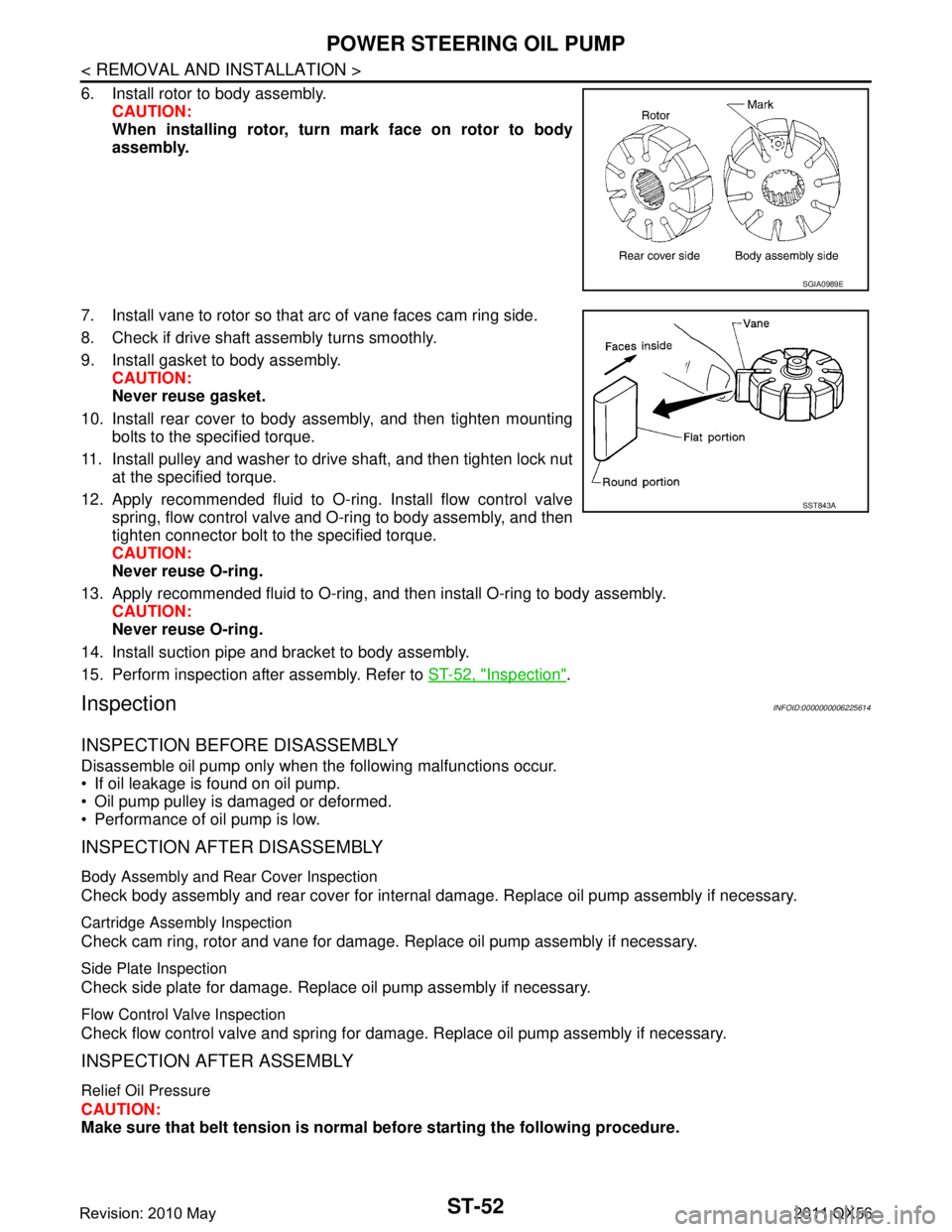
6. Install rotor to body assembly.CAUTION:
When installing rotor, turn mark face on rotor to body
assembly.
7. Install vane to rotor so that arc of vane faces cam ring side.
8. Check if drive shaft assembly turns smoothly.
9. Install gasket to body assembly. CAUTION:
Never reuse gasket.
10. Install rear cover to body assembly, and then tighten mounting bolts to the specified torque.
11. Install pulley and washer to drive shaft, and then tighten lock nut at the specified torque.
12. Apply recommended fluid to O-ring. Install flow control valve spring, flow control valve and O-ring to body assembly, and then
tighten connector bolt to the specified torque.
CAUTION:
Never reuse O-ring.
13. Apply recommended fluid to O-ring, and then install O-ring to body assembly. CAUTION:
Never reuse O-ring.
14. Install suction pipe and bracket to body assembly.
15. Perform inspection after assembly. Refer to ST-52, "
Inspection".
InspectionINFOID:0000000006225614
INSPECTION BEFORE DISASSEMBLY
Disassemble oil pump only when the following malfunctions occur.
If oil leakage is found on oil pump.
Oil pump pulley is damaged or deformed.
Performance of oil pump is low.
INSPECTION AFTER DISASSEMBLY
Body Assembly and Rear Cover Inspection
Check body assembly and rear cover for internal damage. Replace oil pump assembly if necessary.
Cartridge Assembly Inspection
Check cam ring, rotor and vane for damage. Replace oil pump assembly if necessary.
Side Plate Inspection
Check side plate for damage. Replace oil pump assembly if necessary.
Flow Control Valve Inspection
Check flow control valve and spring for damage. Replace oil pump assembly if necessary.
INSPECTION AFTER ASSEMBLY
Relief Oil Pressure
CAUTION:
Make sure that belt tension is normal before starting the following procedure.
SGIA0989E
SST843A
Revision: 2010 May2011 QX56
Page 5095 of 5598
![INFINITI QX56 2011 Factory Service Manual
PRECAUTIONSTM-7
< PRECAUTION > [7AT: RE7R01B]
C
EF
G H
I
J
K L
M A
B
TM
N
O P
Disassembly should be done in a clean work area.
Use lint-free paper or towels for wiping parts clean. Common shop r INFINITI QX56 2011 Factory Service Manual
PRECAUTIONSTM-7
< PRECAUTION > [7AT: RE7R01B]
C
EF
G H
I
J
K L
M A
B
TM
N
O P
Disassembly should be done in a clean work area.
Use lint-free paper or towels for wiping parts clean. Common shop r](/manual-img/42/57033/w960_57033-5094.png)
PRECAUTIONSTM-7
< PRECAUTION > [7AT: RE7R01B]
C
EF
G H
I
J
K L
M A
B
TM
N
O P
Disassembly should be done in a clean work area.
Use lint-free paper or towels for wiping parts clean. Common shop rags can leave fibers that could interfere
with the operation of the transmission.
Place disassembled parts in order for easier and proper assembly.
All parts should be carefully cleaned with a general purpose, non-flammable solvent before inspection or
reassembly.
Gaskets, seals and O-rings should be repl aced any time the A/T is disassembled.
It is very important to perform func tional tests whenever they are indicated.
The valve body contains precision parts and requires extreme care when parts are removed and serviced.
Place disassembled valve body parts in order for easier and proper assembly. Care will also prevent springs
and small parts from becoming scattered or lost.
Properly installed valves, sleeves, plugs, etc. will slide along bores in valve body under their own weight.
Before assembly, apply a coat of recommended ATF to all parts. Apply petroleum jelly to protect O-rings and
seals, or hold bearings and washers in place during assembly. Never use grease.
Extreme care should be taken to avoid damage to O-rings, seals and gaskets when assembling.
When the A/T drain plug is removed, only some of the ATF is drained. Old ATF will remain in torque con- verter and ATF cooling system.
Always follow the procedures under “Changing” when changing ATF. Refer to TM-94, "
Changing".
Occasionally, the parking gear may be locked with the to rque insufficiently released, when stopping the vehi-
cle by shifting the selector lever from “D” or “R” to “P” position with the brake pedal depressed.
In this case, the shock with a thud caused by the abrupt release of torque may occur when shifting the selec-
tor lever from “P” posit ion to other positions.
However, this symptom is not a malfunction which results in the damage of parts.
Service Notice or PrecautionINFOID:0000000006274263
ATF COOLER SERVICE
If ATF contains frictional material (clutches, bands, etc. ), or if an A/T is repaired, overhauled, or replaced,
inspect and clean the A/T fluid cooler mounted in the radiat or or replace the radiator. Flush cooler lines using
cleaning solvent and compressed air after repair. For A/T fluid cooler cleaning procedure, refer to TM-97,
"Cleaning". For radiator replacement, refer to CO-13, "Exploded View".
Revision: 2010 May2011 QX56
Page 5098 of 5598
![INFINITI QX56 2011 Factory Service Manual
TM-10
< SYSTEM DESCRIPTION >[7AT: RE7R01B]
COMPONENT PARTS
SYSTEM DESCRIPTION
COMPONENT PARTS
A/T CONTROL SYSTEM
A/T CONTROL SYSTEM : Co
mponent Parts LocationINFOID:0000000006226738
1. Yaw rate/side INFINITI QX56 2011 Factory Service Manual
TM-10
< SYSTEM DESCRIPTION >[7AT: RE7R01B]
COMPONENT PARTS
SYSTEM DESCRIPTION
COMPONENT PARTS
A/T CONTROL SYSTEM
A/T CONTROL SYSTEM : Co
mponent Parts LocationINFOID:0000000006226738
1. Yaw rate/side](/manual-img/42/57033/w960_57033-5097.png)
TM-10
< SYSTEM DESCRIPTION >[7AT: RE7R01B]
COMPONENT PARTS
SYSTEM DESCRIPTION
COMPONENT PARTS
A/T CONTROL SYSTEM
A/T CONTROL SYSTEM : Co
mponent Parts LocationINFOID:0000000006226738
1. Yaw rate/side/decel G sensor
Refer to BRC-10, "
Component Parts
Location". 2.
Tow mode switch
*13. IPDM E/R
Refer to PCS-4, "
Component Parts
Location".
4. ECM Refer to EC-16, "
Component Parts
Location". 5. ABS actuator and electric unit (con-
trol unit)
Refer to BRC-10, "Component Parts
Location". 6. Accelerator pedal position sensor
Refer to EC-16, "
Component Parts
Location".
7. Stop lamp switch Refer to BRC-10, "
Component Parts
Location". 8. BCM
Refer to BCS-4, "
BODY CONTROL
SYSTEM : Component Parts Loca-
tion". 9. Combination meter
Refer to MWI-6, "
METER SYSTEM :
Component Parts Location".
10. Shift position indicator (In the information display in the
combination meter) 11. A/T CHECK indicator lamp
(On the combination meter) 12. Tow mode indicator lamp
13. Selector lever position indicator 14. Manual mode switch 15. A/T assembly connector
16. Output speed sensor
*217.Control valve & TCM*3
A. Center console B. A/T shift selector assembly C. A/T assembly
*1 : Tow mode switch is integrated in to SNOW MODE/TOW MODE/VDC OFF switch assembly (2WD models) or 4WD switch
assembly (4WD models).
*2 : Output speed sensor is installed in A/T assembly.
*3 : Control valve & TCM is installed in A/T assembly.
JSDIA1773GB
Revision: 2010 May2011 QX56
Page 5099 of 5598
![INFINITI QX56 2011 Factory Service Manual
COMPONENT PARTSTM-11
< SYSTEM DESCRIPTION > [7AT: RE7R01B]
C
EF
G H
I
J
K L
M A
B
TM
N
O P
NOTE:
The following components are included in the control valve & TCM (17).
TCM
Input speed sensor 1, 2
INFINITI QX56 2011 Factory Service Manual
COMPONENT PARTSTM-11
< SYSTEM DESCRIPTION > [7AT: RE7R01B]
C
EF
G H
I
J
K L
M A
B
TM
N
O P
NOTE:
The following components are included in the control valve & TCM (17).
TCM
Input speed sensor 1, 2](/manual-img/42/57033/w960_57033-5098.png)
COMPONENT PARTSTM-11
< SYSTEM DESCRIPTION > [7AT: RE7R01B]
C
EF
G H
I
J
K L
M A
B
TM
N
O P
NOTE:
The following components are included in the control valve & TCM (17).
TCM
Input speed sensor 1, 2
A/T fluid temperature sensor
Transmission range switch
Direct clutch solenoid valve
High and low reverse clutch solenoid valve
Input clutch solenoid valve
Front brake solenoid valve
Low brake solenoid valve
Anti-interlock solenoid valve
2346 brake solenoid valve
Line pressure solenoid valve
Torque converter clutch solenoid valve
A/T CONTROL SYSTEM : Component DescriptionINFOID:0000000006226739
Name Function
TCM TM-12, "
A/T CONTROL SYSTEM : TCM"
Transmission range switchTM-12, "A/T CONTROL SYSTEM : Transmission Range Switch"
Output speed sensor TM-12, "A/T CONTROL SYSTEM : Output Speed Sensor"
Input speed sensor 1
TM-12, "A/T CONTROL SYSTEM : Input Speed Sensor"Input speed sensor 2
A/T fluid temperature sensorTM-12, "
A/T CONTROL SYSTEM : A/T Fluid Temperature Sensor"
Input clutch solenoid valve TM-12, "A/T CONTROL SYSTEM : Input Clutch Solenoid Valve"
Front brake solenoid valve TM-12, "A/T CONTROL SYSTEM : Front Brake Solenoid Valve"
Direct clutch solenoid valveTM-12, "A/T CONTROL SYSTEM : Direct Clutch Solenoid Valve"
High and low reverse clutch solenoid valveTM-13, "A/T CONTROL SYSTEM : High and Low Reverse Clutch Solenoid Valve"
Low brake solenoid valve TM-13, "A/T CONTROL SYSTEM : Low Brake Solenoid Valve"
Anti-interlock solenoid valve TM-13, "A/T CONTROL SYSTEM : Anti-interlock Solenoid Valve"
2346 brake solenoid valve TM-13, "A/T CONTROL SYSTEM : 2346 Brake Solenoid Valve"
Torque converter clutch solenoid valveTM-13, "A/T CONTROL SYSTEM : Torque Converter Clutch Solenoid Valve"
Line pressure solenoid valve TM-13, "A/T CONTROL SYSTEM : Line Pressure Solenoid Valve"
Accelerator pedal position sensor TM-13, "A/T CONTROL SYSTEM : Accelerator Pedal Position Sensor"
Manual mode switch TM-13, "A/T CONTROL SYSTEM : Manual Mode Switch"
Tow mode switch TM-14, "A/T CONTROL SYSTEM : Tow Mode Switch"
A/T CHECK indicator lampTM-14, "A/T CONTROL SYSTEM : A/T CHECK Indicator Lamp"
Tow mode indicator lamp* TM-14, "A/T CONTROL SYSTEM : Tow Mode Indicator Lamp"
Selector lever position indicator TM-14, "A/T CONTROL SYSTEM : Selector Lever Position Indicator"
Stop lamp switch BRC-15, "Stop Lamp Switch"
Yaw rate/side G sensorBRC-15, "Yaw Rate/Side/Decel G sensor"
Starter relay STR-6, "System Description"
ECMEC-35, "ENGINE CONTROL SYSTEM : System Description"
BCM BCS-6, "BODY CONTROL SYSTEM : System Description"
Combination meter MWI-9, "METER SYSTEM : System Description"
ABS actuator and electric unit (control unit) BRC-16, "System Description"
Revision: 2010 May2011 QX56