2011 INFINITI QX56 body int
[x] Cancel search: body intPage 3386 of 5598
LUGGAGE FLOOR TRIMINT-37
< REMOVAL AND INSTALLATION >
C
DE
F
G H
I
K L
M A
B
INT
N
O P
Visually check the clips and pawls for deformation and damage during installation. Replace with new
ones if necessary.
When installing luggage side lo wer finisher, check that clips and pawls are securely fitted in body
panel holes, and press them in.
REAR PILLAR FINISHER
REAR PILLAR FINISHER : Removal and InstallationINFOID:0000000006220262
REMOVAL
1. Remove luggage side lower finisher. INT-36, "LUGGAGE SIDE LOWER FINISHER : Removal and Instal-
lation".
2. Disengage lower side of rear pillar finisher fixing clip.
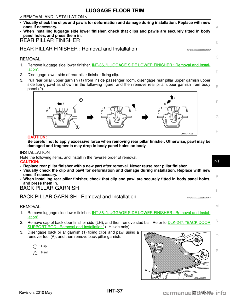
3. Pull rear pillar upper garnish (1) from inside passenger room, disengage rear pillar upper garnish upper side fixing pawl as shown in the following figure, and then remove rear pillar upper garnish from body
panel (2).
CAUTION:
Be careful not to apply excessive force when removing rear pillar finisher. Otherwise, pawl may be
damaged and fragments may drop in body panel holes on body.
INSTALLATION
Note the following items, and install in the reverse order of removal.
CAUTION:
Replace rear pillar finisher wi th a new part after removal. Never reuse rear pillar finisher.
Visually check the clip and pawl for deformation an d damage during installation. Replace with new
ones if necessary.
When installing rear pillar finisher, check that cl ip and pawl are securely fitted in body panel holes,
and press them in.
BACK PILLAR GARNISH
BACK PILLAR GARNISH : Removal and InstallationINFOID:0000000006220263
REMOVAL
1. Remove luggage side lower finisher. INT-36, "LUGGAGE SIDE LOWER FINISHER : Removal and Instal-
lation".
2. Remove cap of back door finisher side (LH), and then remove stud ball. Refer to DLK-247, "
BACK DOOR
SUPPORT ROD : Removal and Installation" (LH side only).
3. Disengage back pillar garnish (1) fixing clips and pawl using a remover tool (A), and then remove back pillar garnish.
JMJIA1176ZZ
: Clip
: Pawl
JMJIA4045ZZ
Revision: 2010 May2011 QX56
Page 3387 of 5598
INT-38
< REMOVAL AND INSTALLATION >
LUGGAGE FLOOR TRIM
INSTALLATION
Note the following items, and install in the reverse order of removal.
CAUTION:
Visually check the clips and pawl for deformation and damage during installation. Replace with new
ones if necessary.
When installing back pillar garnis h, check that clips and pawl are securely fitted in body panel holes,
and press them in.
LUGGAGE SIDE UPPER FINISHER
LUGGAGE SIDE UPPER FINISHER : Removal and InstallationINFOID:0000000006220264
REMOVAL
1. Remove luggage side lower finisher. Refer to INT-36, "LUGGAGE SIDE LOWER FINISHER : Removal
and Installation".
2. Remove rear pillar finisher. Refer to INT-37, "
REAR PILLAR FINISHER : Removal and Installation".
3. Remove back pillar garnish. Refer to INT-37, "
BACK PILLAR GARNISH : Removal and Installation".
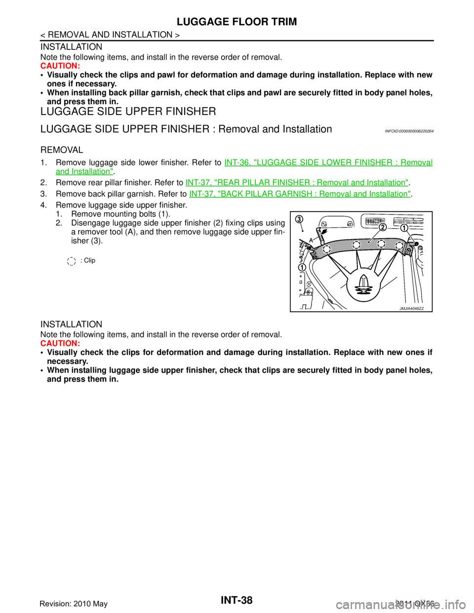
4. Remove luggage side upper finisher. 1. Remove mounting bolts (1).
2. Disengage luggage side upper finisher (2) fixing clips usinga remover tool (A), and then remove luggage side upper fin-
isher (3).
INSTALLATION
Note the following items, and install in the reverse order of removal.
CAUTION:
Visually check the clips for deformation and dama ge during installation. Replace with new ones if
necessary.
When installing luggage side uppe r finisher, check that clips are securely fitted in body panel holes,
and press them in.
: Clip
JMJIA4046ZZ
Revision: 2010 May2011 QX56
Page 3390 of 5598
BACK DOOR TRIMINT-41
< REMOVAL AND INSTALLATION >
C
DE
F
G H
I
K L
M A
B
INT
N
O P
2. Remove back door finisher inner lower.
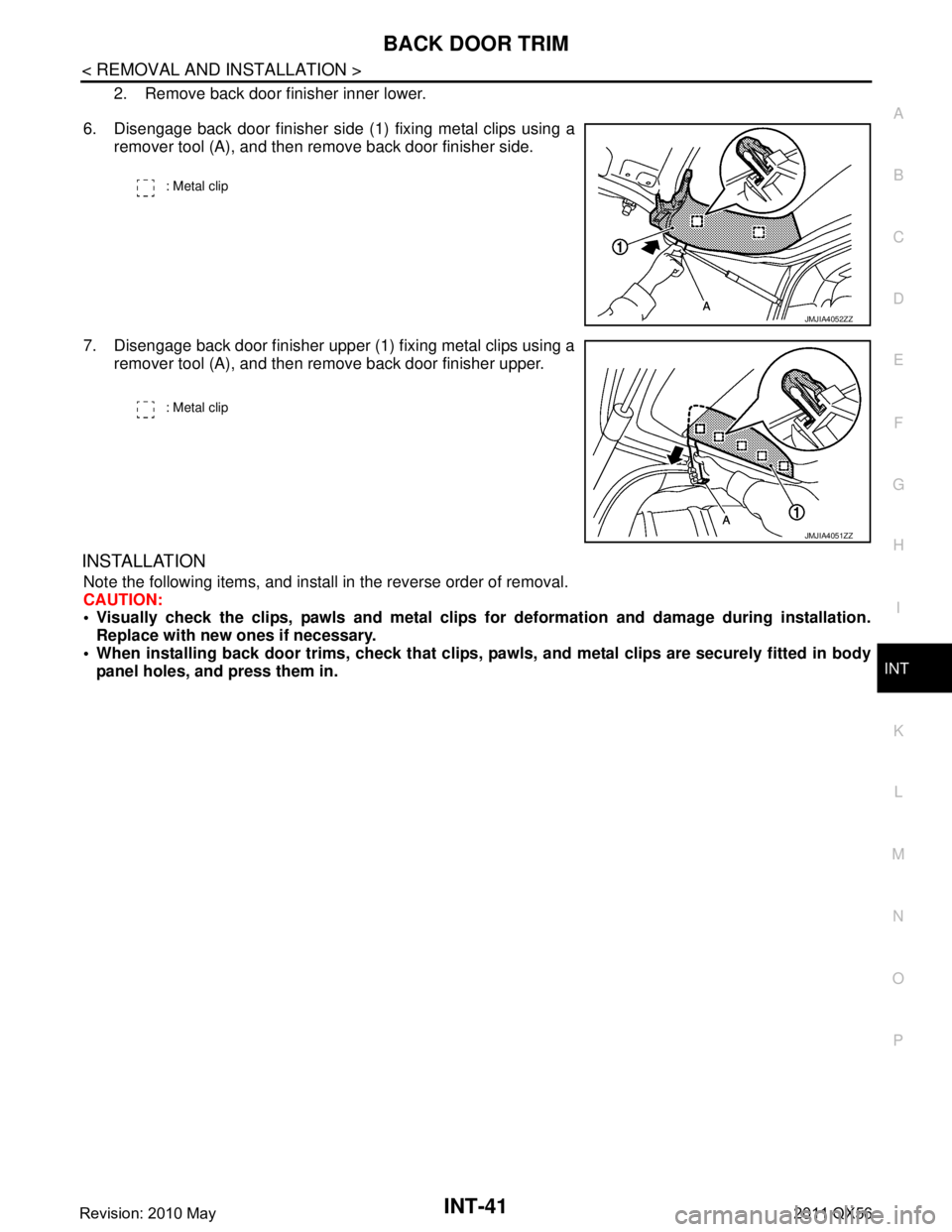
6. Disengage back door finisher side (1) fixing metal clips using a remover tool (A), and then remove back door finisher side.
7. Disengage back door finisher upper (1) fixing metal clips using a remover tool (A), and then remove back door finisher upper.
INSTALLATION
Note the following items, and install in the reverse order of removal.
CAUTION:
Visually check the clips, pawls and metal clips for deformation and damage during installation.
Replace with new ones if necessary.
When installing back door trims, check that clips, pawls, and metal clips are securely fitted in body
panel holes, and press them in.
: Metal clip
JMJIA4052ZZ
: Metal clip
JMJIA4051ZZ
Revision: 2010 May2011 QX56
Page 3391 of 5598
IP-1
BODY INTERIOR
C
DE
F
G H
I
K L
M
SECTION IP
A
B
IP
N
O P
CONTENTS
INSTRUMENT PANEL
PRECAUTION ................ ...............................2
PRECAUTIONS .............................................. .....2
Precaution for Supplemental Restraint System
(SRS) "AIR BAG" and "SEAT BELT PRE-TEN-
SIONER" ............................................................. ......
2
Precaution Necessary for Steering Wheel Rota-
tion after Battery Disconnect .....................................
2
Service ......................................................................3
PREPARATION ............................................4
PREPARATION .............................................. .....4
Special Service Tools ........................................ ......4
Commercial Service Tools .......................................4
CLIP LIST ............................................................6
Clip List ............................................................... ......6
SYMPTOM DIAGNOSIS ...............................7
SQUEAK AND RATTLE TROUBLE DIAG-
NOSES ...............................................................
7
Work Flow ............................................................ .....7
Inspection Procedure ................................................9
Diagnostic Worksheet ..............................................11
REMOVAL AND INSTALLATION ...............13
INSTRUMENT PANEL ASSEMBLY .................13
Exploded View ..................................................... ....13
Removal and Installation .........................................14
CENTER CONSOLE ASSEMBLY ....................23
Exploded View .........................................................23
Removal and Installation .........................................25
Disassembly and Assembly .....................................27
REAR CONSOLE ASSEMBLY .........................29
Exploded View .........................................................29
Removal and Installation .........................................29
Disassembly and Assembly .....................................30
Revision: 2010 May2011 QX56
Page 3398 of 5598
IP-8
< SYMPTOM DIAGNOSIS >
SQUEAK AND RATTLE TROUBLE DIAGNOSES
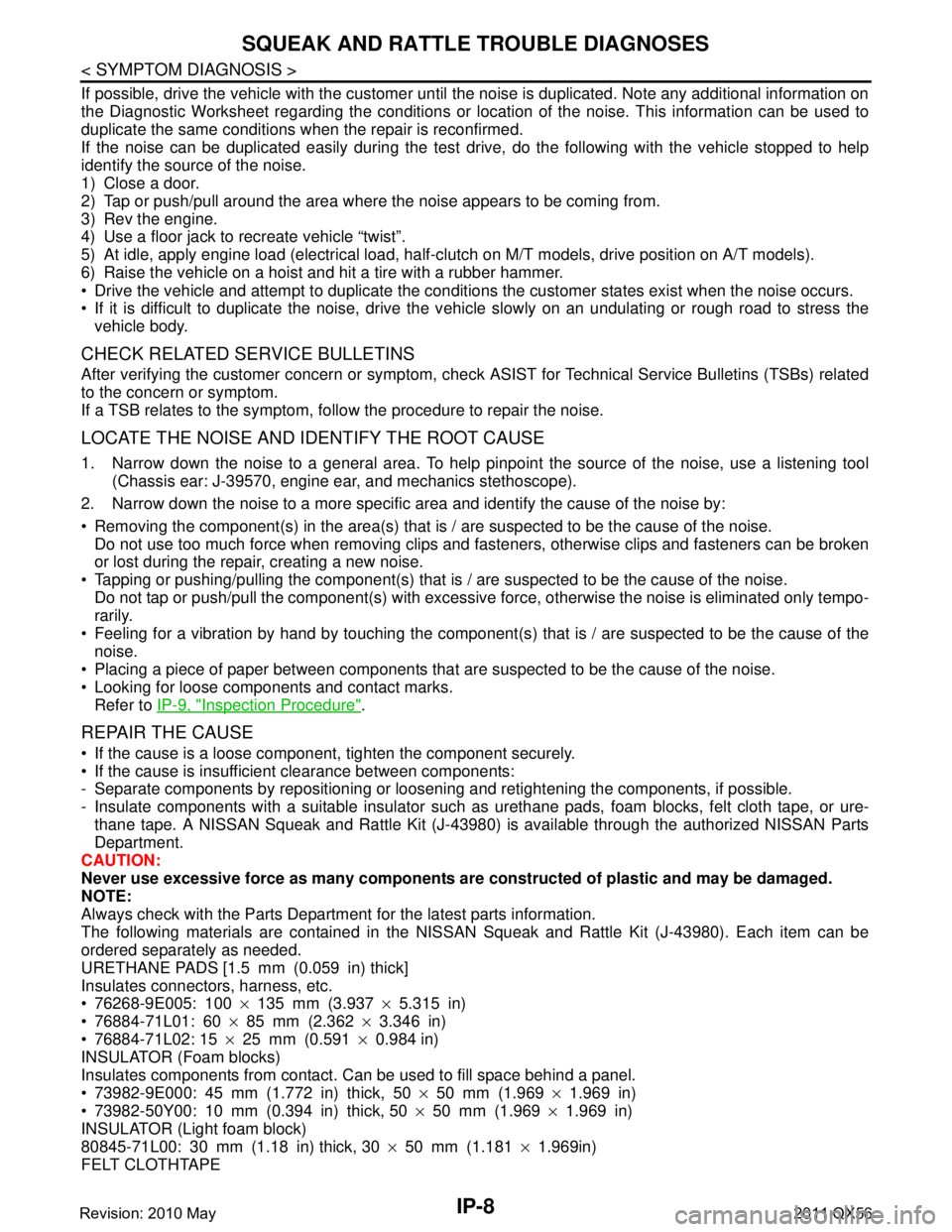
If possible, drive the vehicle with the customer until the noise is duplicated. Note any additional information on
the Diagnostic Worksheet regarding the conditions or lo cation of the noise. This information can be used to
duplicate the same conditions when the repair is reconfirmed.
If the noise can be duplicated easily during the test dr ive, do the following with the vehicle stopped to help
identify the source of the noise.
1) Close a door.
2) Tap or push/pull around the area where the noise appears to be coming from.
3) Rev the engine.
4) Use a floor jack to recreate vehicle “twist”.
5) At idle, apply engine load (electrical load, half-cl utch on M/T models, drive position on A/T models).
6) Raise the vehicle on a hoist and hit a tire with a rubber hammer.
Drive the vehicle and attempt to duplicate the conditions the customer states exist when the noise occurs.
If it is difficult to duplicate the noise, drive the v ehicle slowly on an undulating or rough road to stress the
vehicle body.
CHECK RELATED SERVICE BULLETINS
After verifying the customer concern or symptom, chec k ASIST for Technical Service Bulletins (TSBs) related
to the concern or symptom.
If a TSB relates to the symptom, follo w the procedure to repair the noise.
LOCATE THE NOISE AND IDENTIFY THE ROOT CAUSE
1. Narrow down the noise to a general area. To help pi npoint the source of the noise, use a listening tool
(Chassis ear: J-39570, engine ear, and mechanics stethoscope).
2. Narrow down the noise to a more specific area and identify the cause of the noise by:
Removing the component(s) in the area(s) that is / are suspected to be the cause of the noise.
Do not use too much force when removing clips and fasteners, otherwise clips and fasteners can be broken
or lost during the repair, creating a new noise.
Tapping or pushing/pulling the component(s) that is / are suspected to be the cause of the noise.
Do not tap or push/pull the component(s) with excessive force, otherwise the noise is eliminated only tempo-
rarily.
Feeling for a vibration by hand by touching the component(s ) that is / are suspected to be the cause of the
noise.
Placing a piece of paper between components that are suspected to be the cause of the noise.
Looking for loose components and contact marks. Refer to IP-9, "
Inspection Procedure".
REPAIR THE CAUSE
If the cause is a loose component, tighten the component securely.
If the cause is insufficient clearance between components:
- Separate components by repositioning or loos ening and retightening the components, if possible.
- Insulate components with a suitable insulator such as urethane pads, foam blocks, felt cloth tape, or ure-
thane tape. A NISSAN Squeak and Rattle Kit (J-43980) is available through the authorized NISSAN Parts
Department.
CAUTION:
Never use excessive force as many components are constructed of plastic and may be damaged.
NOTE:
Always check with the Parts Departm ent for the latest parts information.
The following materials are contained in the NISSAN Squeak and Rattle Kit (J-43980). Each item can be
ordered separately as needed.
URETHANE PADS [1.5 mm (0.059 in) thick]
Insulates connectors, harness, etc.
76268-9E005: 100 ×135 mm (3.937 ×5.315 in)
76884-71L01: 60 ×85 mm (2.362 ×3.346 in)
76884-71L02: 15 ×25 mm (0.591 ×0.984 in)
INSULATOR (Foam blocks)
Insulates components from contact. Can be used to fill space behind a panel.
73982-9E000: 45 mm (1.772 in) thick, 50 ×50 mm (1.969 ×1.969 in)
73982-50Y00: 10 mm (0.394 in) thick, 50 ×50 mm (1.969 ×1.969 in)
INSULATOR (Light foam block)
80845-71L00: 30 mm (1.18 in) thick, 30 ×50 mm (1.181 ×1.969in)
FELT CLOTHTAPE
Revision: 2010 May2011 QX56
Page 3407 of 5598
INSTRUMENT PANEL ASSEMBLYIP-17
< REMOVAL AND INSTALLATION >
C
DE
F
G H
I
K L
M A
B
IP
N
O P
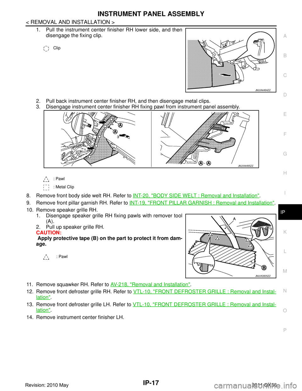
1. Pull the instrument center finisher RH lower side, and then disengage the fixing clip.
2. Pull back instrument center finisher RH, and then disengage metal clips.
3. Disengage instrument center finisher RH fixi ng pawl from instrument panel assembly.
8. Remove front body side welt RH. Refer to INT-20, "
BODY SIDE WELT : Removal and Installation".
9. Remove front pillar garnish RH. Refer to INT-19, "
FRONT PILLAR GARNISH : Removal and Installation".
10. Remove speaker grille RH. 1. Disengage speaker grille RH fixing pawls with remover tool
(A).
2. Pull up speaker grille RH.
CAUTION:
Apply protective tape (B) on the part to protect it from dam-
age.
11. Remove squawker RH. Refer to AV-218, "
Removal and Installation".
12. Remove front defroster grille RH. Refer to VTL-10, "
FRONT DEFROSTER GRILLE : Removal and Instal-
lation".
13. Remove front defroster grille LH. Refer to VTL-10, "
FRONT DEFROSTER GRILLE : Removal and Instal-
lation".
14. Remove instrument center finisher LH.
Clip
JMJIA4494ZZ
: Pawl
: Metal Clip
: Pawl
JMJIA4495ZZ
JMJIA3835ZZ
Revision: 2010 May2011 QX56
Page 3409 of 5598
INSTRUMENT PANEL ASSEMBLYIP-19
< REMOVAL AND INSTALLATION >
C
DE
F
G H
I
K L
M A
B
IP
N
O P
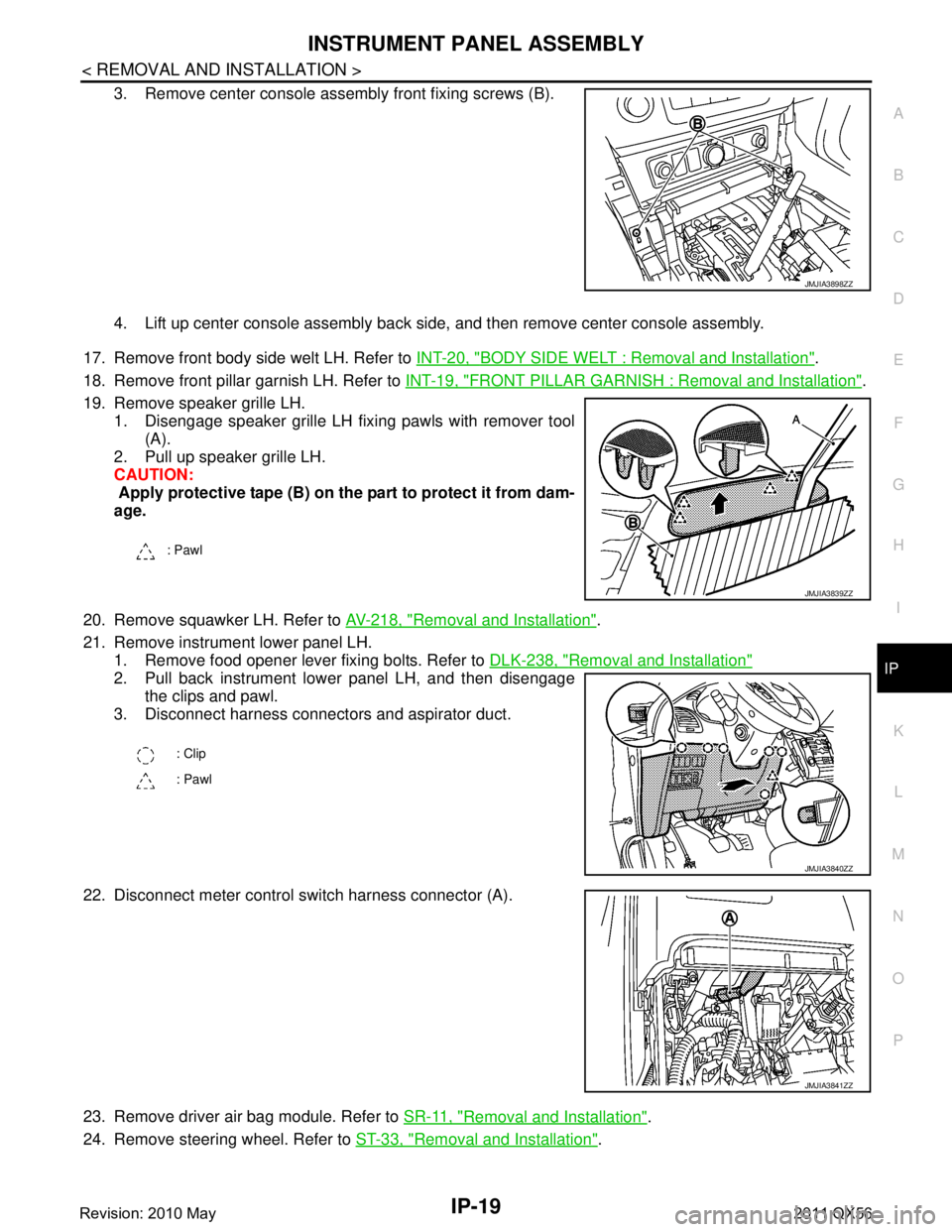
3. Remove center console assembly front fixing screws (B).
4. Lift up center console assembly back side, and then remove center console assembly.
17. Remove front body side welt LH. Refer to INT-20, "
BODY SIDE WELT : Removal and Installation".
18. Remove front pillar garnish LH. Refer to INT-19, "
FRONT PILLAR GARNISH : Removal and Installation".
19. Remove speaker grille LH. 1. Disengage speaker grille LH fixing pawls with remover tool (A).
2. Pull up speaker grille LH.
CAUTION:
Apply protective tape (B) on the part to protect it from dam-
age.
20. Remove squawker LH. Refer to AV-218, "
Removal and Installation".
21. Remove instrument lower panel LH. 1. Remove food opener lever fixing bolts. Refer to DLK-238, "
Removal and Installation"
2. Pull back instrument lower panel LH, and then disengage
the clips and pawl.
3. Disconnect harness connectors and aspirator duct.
22. Disconnect meter control s witch harness connector (A).
23. Remove driver air bag module. Refer to SR-11, "
Removal and Installation".
24. Remove steering wheel. Refer to ST-33, "
Removal and Installation".
JMJIA3898ZZ
: Pawl
JMJIA3839ZZ
: Clip
: Pawl
JMJIA3840ZZ
JMJIA3841ZZ
Revision: 2010 May2011 QX56
Page 3670 of 5598
SERVICE DATA AND SPECIFICATIONS (SDS)
LU-17
< SERVICE DATA AND SPECIFICATIONS (SDS)
C
D E
F
G H
I
J
K L
M A
LU
NP
O
SERVICE DATA AND SPECIFICATIONS (SDS)
SERVICE DATA AND SPECIFICATIONS (SDS)
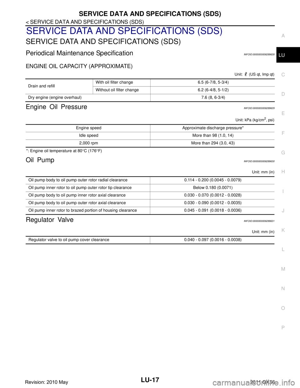
Periodical Maintenance SpecificationINFOID:0000000006289628
ENGINE OIL CAPACITY (APPROXIMATE)
Unit: (US qt, Imp qt)
Engine Oil PressureINFOID:0000000006289629
Unit: kPa (kg/cm2, psi)
*: Engine oil temperature at 80
°C (176 °F)
Oil PumpINFOID:0000000006289630
Unit: mm (in)
Regulator ValveINFOID:0000000006289631
Unit: mm (in)
Drain and refill With oil filter change 6.5 (6-7/8, 5-3/4)
Without oil filter change 6.2 (6-4/8, 5-1/2)
Dry engine (engine overhaul) 7.6 (8, 6-3/4)
Engine speed Approximate discharge pressure* Idle speed More than 98 (1.0, 14)2,000 rpm More than 294 (3.0, 43)
Oil pump body to oil pump outer rotor radial clearance 0.114 - 0.200 (0.0045 - 0.0079)
Oil pump inner rotor to oil pump outer rotor tip clearance Below 0.180 (0.0071)
Oil pump body to oil pump inner rotor axial clearance 0.030 - 0.070 (0.0012 - 0.0028)
Oil pump body to oil pump outer rotor axial clearance 0.030 - 0.090 (0.0012 - 0.0035)
Oil pump inner rotor to brazed portion of housing clearance 0.045 - 0.091 (0.0018 - 0.0036)
Regulator valve to oil pump cover clearance 0.040 - 0.097 (0.0016 - 0.0038)
Revision: 2010 May2011 QX56